
 Download PDF
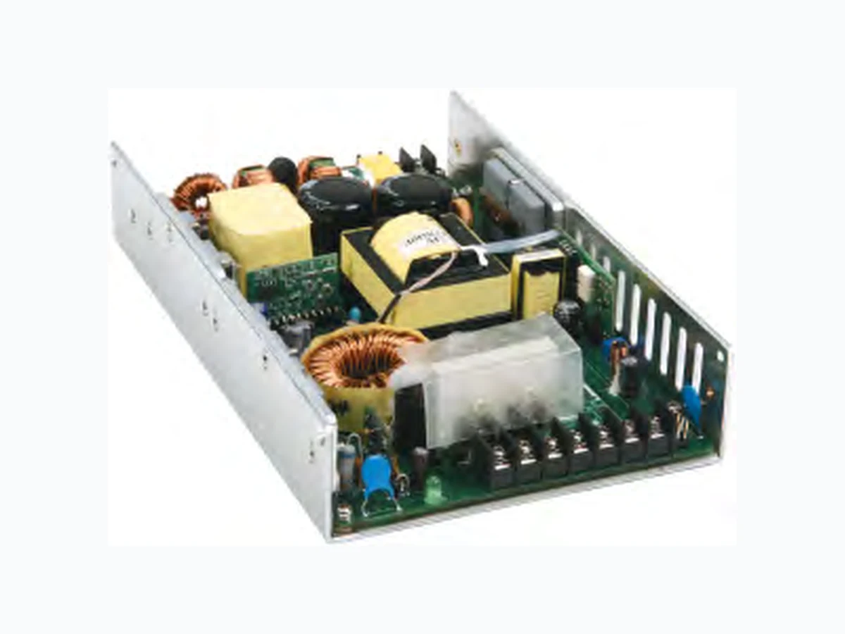
PMK450S ASTRODYNE
Document overview
- PDF pages: 10
Technical content
Page 1

PMK450 series
450 Watt Enclosed and U-Channel Power Supplies with PFC
Line Reg
\*Model Number
Output V Output I
SINGLE OUTPUT
PMK450S-12 U,E,D(-CS)
12 VDC
37.5 Amps
PMK450S-24 U,E,D(-CS)
24 VDC
18.75 Amps
PMK450S-36 U,E,D(-CS)
36 VDC
12.5 Amps
PMK450S-48 U,E,D(-CS)
48 VDC
9.375 Amps
450 Watts Output Power
Single Output
Universal 90-264VAC Input
12VDC to 48VDC Output
4242VDC Input to Output Isolation
Active Power Factor Correction
5 Volt Standby Power
\*\*Optional Current Share (CS) Capability
Load Reg
Ripple
Efficiency
(nom/max)
(nom/max) & Noise
(min/nom)
0.3% / 1.0%
0.3% / 1%
120mV pk-pk
77% / 85%
0.2% / 0.5%
0.2% / 0.5% 240mV pk-pk
78% / 86%
0.1% / 0.5%
0.1% / 0.5% 360mV pk-pk
79% / 86%
0.1% / 0.5%
0.1% / 0.5% 480mV pk-pk
81% / 88%
\*Available in a U-Channel Package (i.e. PMK450S-12U), an Enclosed Package (i.e. PMK450S-12E) or an Enclosed Package with a DIN Rail Clip (i.e. PMK450S-12D)
\*\* The PMK450S Series power supplies are available with current-sharing (CS) option for N+1 paralleling and redundant power applications. To receive this option with your product simply add “-CS” to the end of the Model Number. For example PMK450S-12U-CS. Please see the application note at the end of this specification for instructions on how to utilize.
Page 2

PMK450 series
450 Watt Enclosed and U-Channel Power Supplies with PFC
INPUT SPECIFICATIONS
Input Voltage Range
90-264VAC (100-240VAC Nom.)
Frequency Range
47-63Hz (50-60 Hz Nom.)
Inrush Current, typ: (cold start) 30A at FL, 115VAC
60A at FL, 230VAC
Input Current (90Vin/264Vin) 7A / 2.5A max Power Factor (Nom I/P, FL)
0.95 min
Leakage current
Less than 3.5mA @ 240VAC, 50Hz
OUTPUT SPECIFICATIONS
Voltage and Current
See Selection Chart
5 Volt Standby (+5Vsb)
0~2.0A (See Page 9)
Preset Accuracy
1%
Line Regulation (LL-HL)
See Selection Chart
Load Regulation (20%-FL)
See Selection Chart
DC Output Power
450W, Max (See Derating Curve)
Ripple/Noise
See Selection Chart 20MHz bandwidth with parallel 0.1uF ceramic capacitor 47uF eletrolytic capacitor
Hold Up Time, typ.
16mS at nominal input voltage range
Turn On Delay Time
< 4S
Rise Time
< 25mS @ 110 Vin
Short Curcuit Protection
Auto-recovery\*
Over Voltage Protection
130% (max) Auto-recovery\*
Over Current Protection
150% (max) Auto-recovery\*
Efficiency (without Oring Diode) See Selection Chart
PHYSICAL SPECIFICATIONS
Size (PMK450S-xxU) Millimeters / Inches 203.2x 127x 38 / 8”x 5”x 1.5” Size (PMK450S-xxE, D) Millimeters / Inches 224.9x 127x 40 / 8.85”x 5”x 1.57” Weight U-Bracket (PMK450S-xxU)
33.97 oz (963g)
Enclosed (PMK450S-xxE)
37.32 oz (1058g)
Enclosed w. DIN Clip (PMK450-xxD)
38 oz (1077g)
\* These are stress ratings. Exposure of the devices to any of these conditions may adversely affect long term reliability. Proper operation under conditions other than the standard operating conditions is neither warranteed nor implied.
ENVIRONMENTAL SPECIFICATIONS
Oper. Temperature 0°C to 70°C (See Derate Curve) Storage Temperature -40°C to 85°C Oper. Humidity
10 - 90% for nominal input range Non-condensing
Storage Humidity
5 - 95%
MTBF @ 25°C
100K Hrs min. MIL-HDBK-217F
Vibration\*
4G’S pk, 50~500Hz, 3 AXES. 30 Min
Drop Test \*
70 cm no damage
EMS Harmonics
61000-3-2 Class D
Fluctuations
61000-3-3
ESD
Contact 6KV Air 8KV 61000-4-2
RS
FR: 80MHz-2.5GHz Field Strength: 3V / M 61000-4-3
EFT
2KV on AC power line 61000-4-4
Surge
1KV (L-N) & 2KV (L-PE, N-PE) 61000-4-5
CS
3V (EMF)
61000-4-6
DIPS
95% 250Cy , 70% 25 Cy 40% 5Cy , 5% 0.5Cy 61000-4-11
EMI
CISPR/EN55011 Class B
GENERAL SPECIFICATIONS
Safety UL/cUL:
UL60950-1 2nd ed./ C22.2 60950-1 2nd ed.
UL-EU:
EN60950-1 2nd ed.
CE:
EN60601-1-2
CB:
IEC60950-1 2nd ed.
Over-Shoot and under shoot
Less than 10% of nominal output
Remote sense
0.5V drop. max at terminals
Hi-pot test (60S max)
4242VDC I/P - O/P 2121 VDC I/P - GND 707VDC O/P - GND
Insulation Resistance (I/P-O/P) 500VDC, 1S, ≥ 20MΩ
REMOTE SHUTDOWN
- Open Collector, Logic “1”=On, “0”=Off. No termination with S/D pin to maintain constant “On” operation.
All specifications are typical at nominal input, full load, and 25°C unless otherwise noted
Page 3

PMK450 series
NN OON
EEELLLEEECCCTTTRRRIIICCCAAALLL SSSPPPEEECCCIIIFFFIIICCCAAATTTIIIO
OORRRPPP
NNEEE PPPAAACCCIIIFFFIIICCC CCCO DDYYYN OOD AAASSSTTTRRRO
450 Watt Enclosed and U-Channel Power Supplies with PFC
6.3 Mechanical specification
MECHANICAL DIMENSIONS
U-Bracket (PMK450S-xxU)
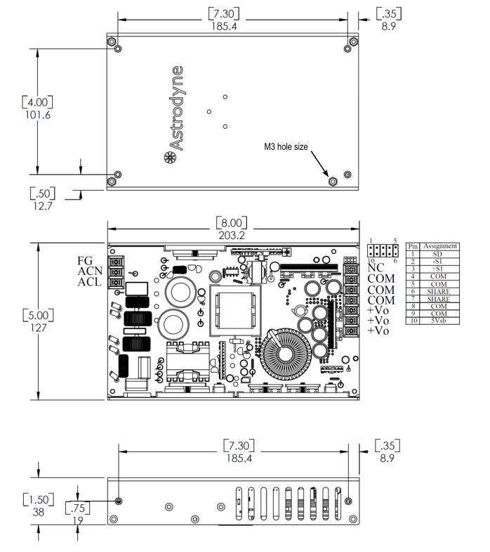
Input connector:3P / 8.25 mm pitch terminal block Output connector:7P / 8.25 mm pitch terminal block
Unit : mm
Page 4

PMK450 series
NN OON
EEELLLEEECCCTTTRRRIIICCCAAALLL SSSPPPEEECCCIIIFFFIIICCCAAATTTIIIO
OORRRPPP NNEEE PPPAAACCCIIIFFFIIICCC CCCO DDYYYN OOD AAASSSTTTRRRO
450 Watt Enclosed and U-Channel Power Supplies with PFC
Enclosed with Fan (PMK450S-xxE):
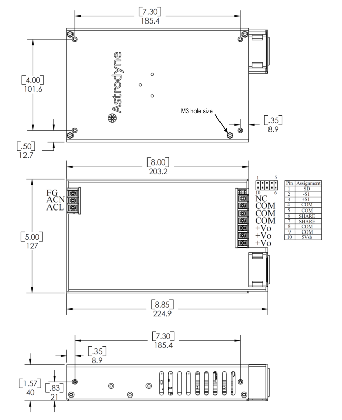
Input connector:3P / 8.25 mm pitch terminal block Output connector:7P / 8.25 mm pitch terminal block
Unit : mm
Page 5

PMK450 series
NN OON
EEELLLEEECCCTTTRRRIIICCCAAALLL SSSPPPEEECCCIIIFFFIIICCCAAATTTIIIO
OORRRPPP NNEEE PPPAAACCCIIIFFFIIICCC CCCO DDYYYN OOD AAASSSTTTRRRO
450 Watt Enclosed and U-Channel Power Supplies with PFC
Din-rail with Fan (PMK450S-xxD):
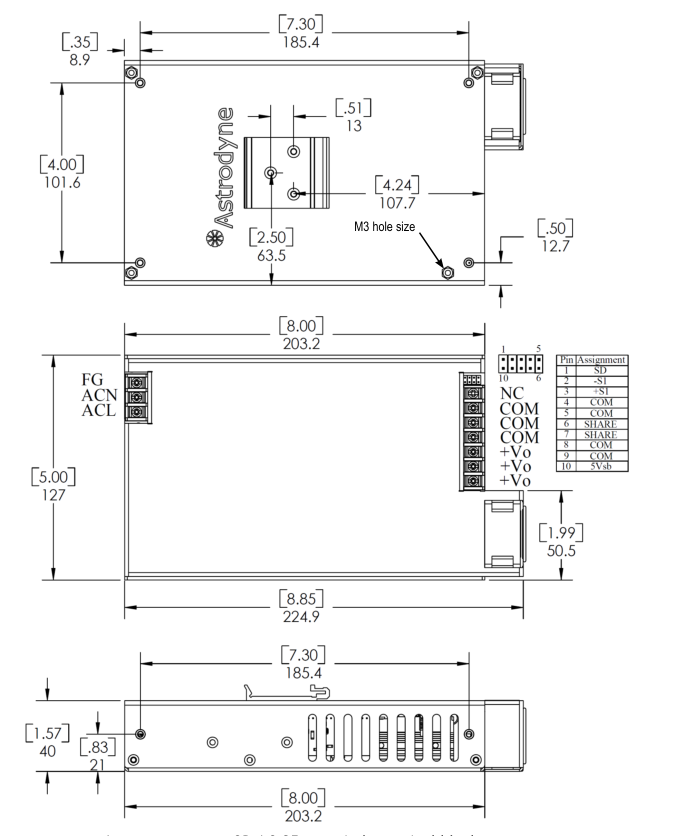
Input connector:3P / 8.25 mm pitch terminal block Output connector:7P / 8.25 mm pitch terminal block
Unit : mm
Page 6

NN OON
EEELLLEEECCCTTTRRRIIICCCAAALLL SSSPPPEEECCCIIIFFFIIICCCAAATTTIIIO
PMK450 series
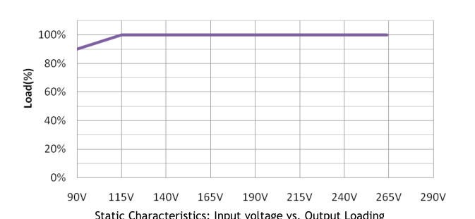
7. Derating Curve
450 Watt Enclosed and U-Channel Power Supplies with PFC
U-Bracket (PMK450S-xxU):
Ambient Temperature Derating Curve
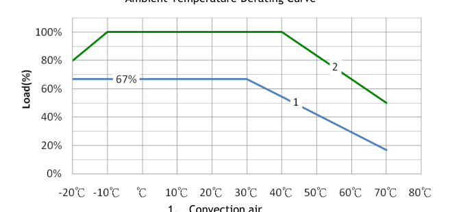
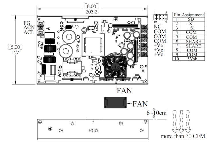
- Forced air cooling (30CFM air flow is required)
Page 7

PMK450 series
450 Watt Enclosed and U-Channel Power Supplies with PFC
NN OON
EEELLLEEECCCTTTRRRIIICCCAAALLL SSSPPPEEECCCIIIFFFIIICCCAAATTTIIIO
OORRRPPP
NNEEE PPPAAACCCIIIFFFIIICCC CCCO DDYYYN OOD AAASSSTTTRRRO
Diagram of external fan placement
U-Bracket (PMK450S-xxU):
Page 8

PMK450 series
450 Watt Enclosed and U-Channel Power Supplies with PFC
NN OON
EEELLLEEECCCTTTRRRIIICCCAAALLL SSSPPPEEECCCIIIFFFIIICCCAAATTTIIIO
OORRRPPP
NNEEE PPPAAACCCIIIFFFIIICCC CCCO DDYYYN OOD AAASSSTTTRRRO
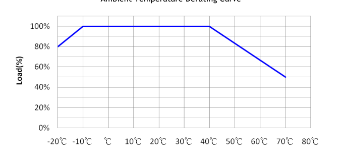
Enclosed & Din-rail (PMK450S-xxE/D):
Ambient Temperature Derating Curve
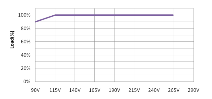
Static Characteristics (Input voltage vs. Output Loading)
Page 9
capacitors and measured band width with DC 20MHz. \*2. Regulation included line, temperature drift etc tolerance variation. \*3. Load regulation measured from 20% to Full load.

\*4. The efficiency is defined without Oring Diode. \*5. All measurements should be made directly at the terminals of the power
PMK450 series
450 Watt Enclosed and U-Channel Power Supplies with PFC
\*6. All specifications typical @ 25℃, unless otherwise noted, at nominal line and load.
+5Vsb Standby Power:
| PMK450S-xx SPECIFICATION | 5Vsb | ||
| Min | Nom | Max | |
| DC OUTPUT VOLTAGE (V) | 4.85 | 5 | 5.15 |
| PRESET ACCURACY (%) | 1 | ||
| OUTPUT CURRENT (A) | 0 | 1.0 | 2.0 |
| O/P NOISE (P-P, mV) *1 | 75 | ||
| REGULATION (%) *2 | 1 | ||
| LOAD REGULATION (%) *3 | 1.0 | 2.0 | |
+5Vsb is a standby output voltage that is always active whenever AC power is present. +5Vsb supplies 1.0A current in normal operation and is capable of withstanding maximum 10W (2 Amps) peak power for 10 seconds. +5Vsb provides a power source for circuits that must remain operational when DC main output is in sleep/off state. +5Vsb over current protection is built internal to its controller. 5Vsb OCP trip point is set to be within 2.5A - 5A. 5Vsb OVP is clamp.
Page 10

PMK450 series
450 Watt Enclosed and U-Channel Power Supplies with PFC
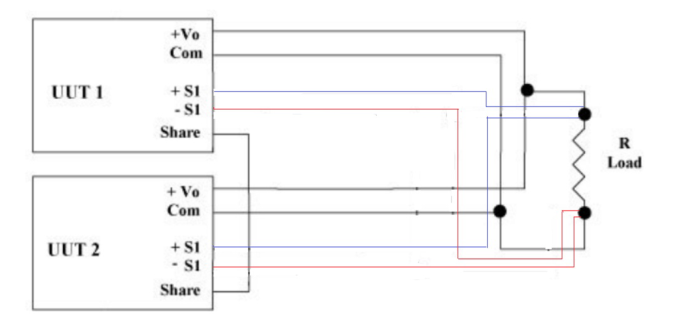
Parallel Operation Instructions \*
1.) Follow wiring diagram below 2.) No external oring diodes needed, oring diodes are built in with current share option 3.) Keep wires as short as possible to avoid noise pickup
\*Notes: Applications for increased power not to exceed 800 Watts Parallel operation of PMK450 not recommended for Medical Applications due to increased leakage current