

 Download PDF
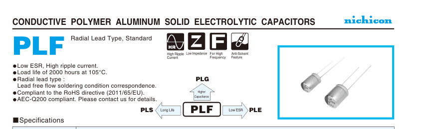
PLF NICHICON
Document overview
- PDF pages: 2
Technical content
Page 1
| Item | Performance Characteristics |
| Category Temperature Range | –55 to +105°C |
| Rated Voltage Range | 2.5 to 25V |
| Rated Capacitance Range | 6.8 to 1500µF |
| Capacitance Tolerance | ± 20% at 120Hz, 20°C |
| Tangent of loss angle (tan δ) | Less than or equal to the specified value at 120Hz, 20°C |
| ESR ( 1) | Less than or equal to the specified value at 100kHz, 20°C |
| Leakage Current ( 2) | Less than or equal to the specified value. After 2 minutes' application of rated voltage at 20°C |
| Temperature Characteristics (Max.Impedance Ratio) | Z+105°C / Z+20°C 1.25 (100kHz) Z–55°C / Z+20°C 1.25 |
| Endurance | Capacitance change Within ± 20% of the initial capacitance value ( 3) The specifications listed at right shall be met when the tan δ 150% or less than the initial specified value capacitors are restored to 20°C after the rated voltage is ESR ( 1) 150% or less than the initial specified value applied for 2000 hours at 105°C. Leakage current ( 2) Less than or equal to the initial specified value |
| Damp Heat (Steady State) | Capacitance change Within ± 20% of the initial capacitance value ( 3) The specifications listed at right shall be met when the tan δ 150% or less than the initial specified value capacitors are restored to 20°C after the rated voltage is ESR ( 1) 150% or less than the initial specified value applied for 1000 hours at 60°C, 90% RH. Leakage current ( 2) Less than or equal to the initial specified value |
| Resistance to Soldering Heat Marking | After soldering the capacitor under the soldering conditions Capacitance change Within ± 10% of the initial capacitance value ( 3) prescribed here as preheat at 150 to 200°C for 60 to 180 seconds tan δ 130% or less than the initial specified value and peak temperature at 265°C for 10 seconds or less, the ESR ( 1) 130% or less than the initial specified value capacitor shall meet the specifications listed at right, provided that Leakage current ( 2) Less than or equal to the initial specified value its temperature profile is measured at both of terminal ends facing the soldering side. Navy blue print on the case top |
1 ESR should be measured at both of the terminal ends closest to the capacitor body. 2 Conditioning : If any doubt arises, measure the leakage current after the voltage treatment of applying DC rated voltage continuously to the capacitor for 120
minutes at 105°C.
3 Initial value : The value before test of examination of resistance to soldering.
Dimensions
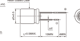
Resin coated Case
Capacitance
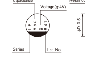
Type numbering system (Example : 4V 560µF)
1 2 3 4 5 6 7 8 9 10 11 12
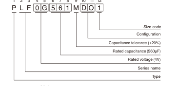
(mm) Voltage
| Size | φ6.3 × 6L | φ6.3 × 9L | φ6.3 × 10.5L φ8 × 7L φ8 × 9L φ8 × 1 | 2L φ10 × 8L φ10 × 10Lφ10 × 13L |
| φD | 6.3 | 6.3 | 6.3 8.0 8.0 8.0 | 10.0 10.0 10.0 |
| L | 5.5 | 8.5 | 10.0 6.5 8.5 11.5 | 7.5 9.5 12.5 |
| P | 2.5 | 2.5 | 2.5 3.5 3.5 3.5 | 5.0 5.0 5.0 |
| φd | 0.45 | 0.6 | 0.5 0.6 0.6 0.6 | 0.6 0.6 0.6 |
| V | 2.5 | 4 | 6.3 | 10 | 16 | 20 | 25 |
| Code | e | g | j | A | C | D | E |
Frequency coefficient of rated ripple current
| 0 Frequency0/ | 120Hz | 1kHz | 10kHz | 100kHz or more |
| Coefficient | 0.05 | 0.30 | 0.70 | 1.00 |
Please refer to page 20 about the end seal configuration.
Dimension table in next page.
CAT.8100H
Page 2
CONDUCTIVE POLYMER ALUMINUM SOLID ELECTROLYTIC CAPACITORS
PLF
Dimensions
| Rated Voltage (V)(code) | Surge Voltage (V) | Rated Capacitance (µF) | Case Size φD × L (mm) | tan δ | Leakage Current (µA) | ESR (mΩ) (at 100kHz 20°C) | Rated Ripple (mArms) | Part Number | |
|---|---|---|---|---|---|---|---|---|---|
| 2.5 (0E) | 2.8 | 330 | 6.3 × 9 | 0.08 | 500 | 7 | 5600 | PLF0E331MCO8 | |
| 390 | 6.3 × 10.5 | 0.08 | 195 | 20 | 3200 | PLF0E391MDL4 | |||
| 560 | 6.3 × 9 | 0.08 | 500 | 7 | 5600 | PLF0E561MCO8 | |||
| 560 | 8 × 9 | 0.08 | 280 | 6 | 4800 | PLF0E561MCO1 | |||
| 680 | 8 × 9 | 0.08 | 340 | 7 | 4800 | PLF0E681MCO6 | |||
| 680 | 8 × 12 | 0.08 | 340 | 6 | 5700 | PLF0E681MDO1 | |||
| 820 | 6.3 × 9 | 0.08 | 500 | 7 | 5600 | PLF0E821MCO8 | |||
| 820 | 8 × 9 | 0.08 | 410 | 7 | 5200 | PLF0E821MCO6 | |||
| 820 | 8 × 12 | 0.08 | 410 | 6 | 6200 | PLF0E821MDO1 | |||
| 1000 | 10 × 13 | 0.08 | 500 | 6 | 6500 | PLF0E102MDO1 | |||
| 1200 | 10 × 13 | 0.08 | 600 | 8 | 5300 | PLF0E122MDO1 | |||
| 1500 | 8 × 12 | 0.08 | 750 | 7 | 6100 | PLF0E152MDO6 | |||
| 1500 | 10 × 13 | 0.08 | 750 | 8 | 5500 | PLF0E152MDO1 | |||
| 4 (0G) | 4.6 | 270 | 6.3 × 9 | 0.08 | 500 | 7 | 5600 | PLF0G271MCO8 | |
| 270 | 6.3 × 10.5 | 0.08 | 216 | 20 | 3200 | PLF0G271MDL4 | |||
| 390 | 6.3 × 10.5 | 0.08 | 312 | 24 | 3300 | PLF0G391MDL4 | |||
| 560 | 8 × 9 | 0.08 | 448 | 7 | 5200 | PLF0G561MCO6 | |||
| 560 | 8 × 12 | 0.08 | 448 | 7 | 5500 | PLF0G561MDO1 | |||
| 680 | 8 × 12 | 0.08 | 544 | 6 | 6200 | PLF0G681MDO1 | |||
| 820 | 10 × 13 | 0.08 | 656 | 6 | 6500 | PLF0G821MDO1 | |||
| 1000 | 10 × 13 | 0.08 | 800 | 6 | 6640 | PLF0G102MDO1 | |||
| 1200 | 10 × 13 | 0.08 | 960 | 8 | 5600 | PLF0G122MDO1 | |||
| 6.3 (0J) | 7.2 | 220 | 6.3 × 10.5 | 0.08 | 277 | 20 | 3200 | PLF0J221MDL4 | |
| 330 | 6.3 × 10.5 | 0.08 | 416 | 24 | 3300 | PLF0J331MDL4 | |||
| 470 | 8 × 9 | 0.08 | 592 | 7 | 5200 | PLF0J471MCO6 | |||
| 470 | 8 × 12 | 0.08 | 592 | 7 | 5500 | PLF0J471MDO1 | |||
| 680 | 10 × 13 | 0.08 | 857 | 6 | 6300 | PLF0J681MDO1 | |||
| 10 (1A) | 11.5 | 47 | 6.3 × 10.5 | 0.08 | 94 | 25 | 2900 | PLF1A470MDL4 | |
| 68 | 6.3 × 10.5 | 0.08 | 136 | 25 | 2900 | PLF1A680MDL4 | |||
| 100 | 6.3 × 10.5 | 0.08 | 200 | 25 | 2900 | PLF1A101MDL4 | |||
| 150 | 6.3 × 10.5 | 0.08 | 300 | 25 | 2900 | PLF1A151MDL4 | |||
| 270 | 8 × 12 | 0.08 | 540 | 8 | 4900 | PLF1A271MDO1 | |||
| 470 | 10 × 13 | 0.08 | 940 | 7 | 5700 | PLF1A471MDO1 | |||
| 560 | 10 × 13 | 0.08 | 1120 | 7 | 5900 | PLF1A561MDO1 | |||
| 680 | 10 × 13 | 0.08 | 1360 | 7 | 6100 | PLF1A681MDO1 | |||
| 16 (1C) | 18.4 | 100 | 6.3 × 10.5 | 0.08 | 320 | 24 | 2900 | PLF1C101MDL4 | |
| 180 | 8 × 12 | 0.08 | 576 | 9 | 5000 | PLF1C181MDO1 | |||
| 270 | 8 × 12 | 0.08 | 864 | 9 | 5100 | PLF1C271MDO1 | |||
| 330 | 10 × 13 | 0.08 | 1056 | 9 | 6100 | PLF1C331MDO1 | |||
| 470 | 10 × 13 | 0.08 | 1504 | 9 | 6100 | PLF1C471MDO1 | |||
| 20 (1D) | 23 | 22 | 6.3 × 6 | 0.12 | 88 | 50 | 1700 | PLF1D220MCL2 | |
| 39 | 8 × 7 | 0.12 | 156 | 45 | 2000 | PLF1D390MCL2 | |||
| 47 | 8 × 7 | 0.12 | 188 | 45 | 2000 | PLF1D470MCL2 | |||
| 56 | 10 × 8 | 0.12 | 224 | 40 | 2400 | PLF1D560MCL2 | |||
| 68 | 10 × 8 | 0.12 | 272 | 40 | 2600 | PLF1D680MCL2 | |||
| 82 | 10 × 8 | 0.12 | 328 | 40 | 2600 | PLF1D820MCL2 | |||
| 100 | 8 × 12 | 0.12 | 400 | 22 | 3320 | PLF1D101MDO2 | |||
| 120 | 10 × 10 | 0.12 | 480 | 35 | 2800 | PLF1D121MCL2 | |||
| 150 | 10 × 13 | 0.12 | 600 | 20 | 4320 | PLF1D151MDO2 | |||
| 25 (1E) | 28.7 | 6.8 | 6.3 × 6 | 0.12 | 85 | 80 | 1200 | PLF1E6R8MCL2 | |
| 10 | 6.3 × 6 | 0.12 | 125 | 65 | 1500 | PLF1E100MCL7 | |||
| 10 | 8 × 7 | 0.12 | 125 | 60 | 1500 | PLF1E100MCL2 | |||
| 22 | 8 × 7 | 0.12 | 275 | 50 | 1800 | PLF1E220MCL7 | |||
| 47 | 10 × 13 | 0.12 | 588 | 30 | 3000 | PLF1E470MDO2 | |||
| 56 | 10 × 13 | 0.12 | 700 | 28 | 3800 | PLF1E560MDO2 | |||
Rated ripple current (mArms) at 105°C 100kHz
No marked, 1 will be put at 12th digit of type numbering system. : In this case, 2 will be put at 12th digit of type numbering system.
Please refer to page 20, 21, 22 about the formed or taped product spec.
: In this case, 4 will be put at 12th digit of type numbering system.
Please refer to page 3 for the minimum order quantity.
: In this case, 6 will be put at 12th digit of type numbering system. : In this case, 7 will be put at 12th digit of type numbering system. CAT.8100H : In this case, 8 will be put at 12th digit of type numbering system.