
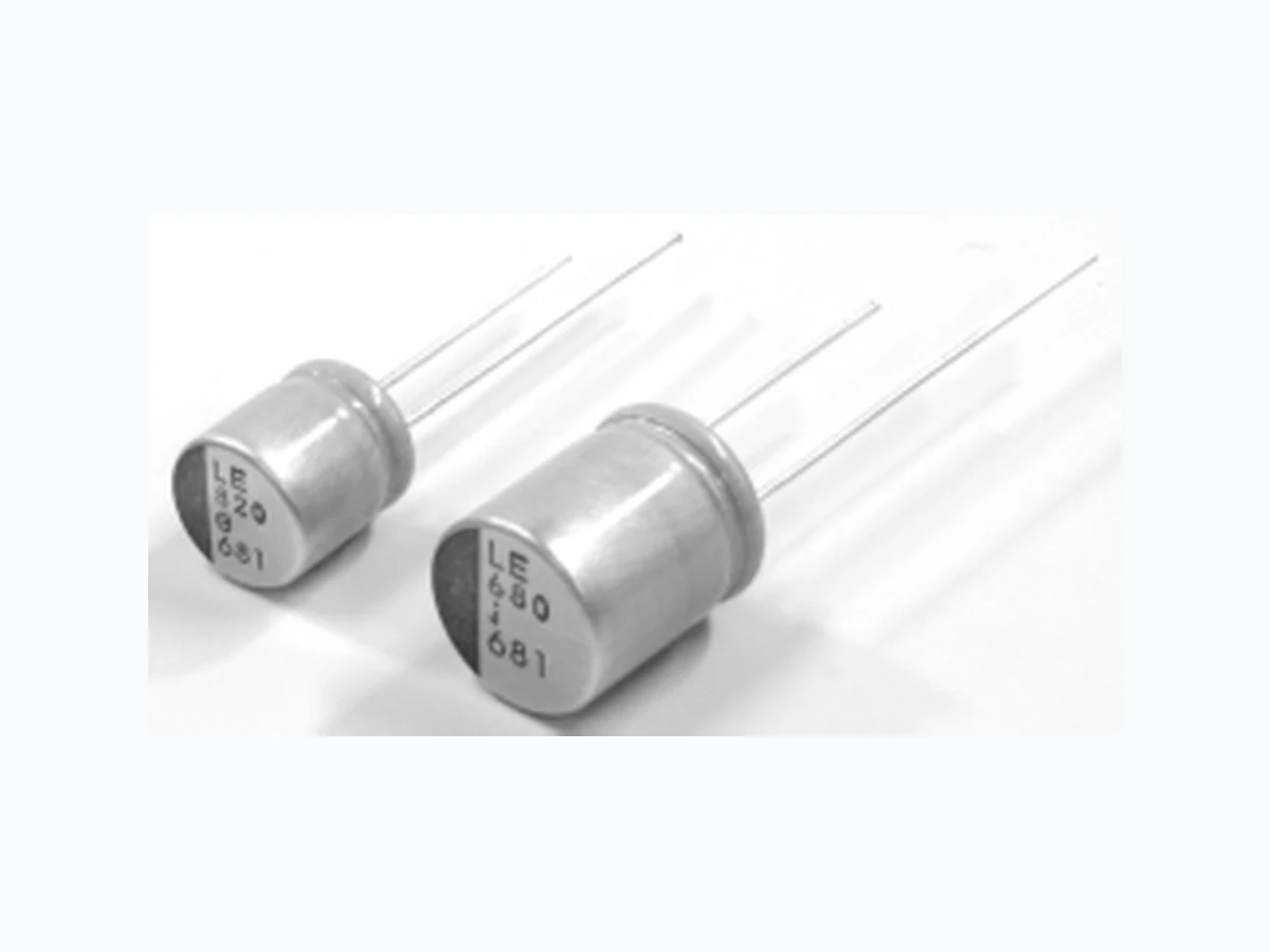

 Download PDF
PLE0E561MCO1 NICHICON
Document overview
- PDF pages: 2
Technical content
Page 1
CONDUCTIVE POLYMER
ALUMINUM SOLID ELECTROLYTIC CAPACITORS
LE
Ultra Low ESR
series
Ultra Low ESR, High ripple current. Load life of 2000 hours at 105°C. Radial lead type :
LE
Lead free flow soldering condition correspondence
LF Low ESR
Adapted to the RoHS directive (2002/95/EC).
Specifications
| Item | Performance Characteristics |
| Category Temperature Range | –55 ~ +105°C |
| Rated Voltage Range | 2.5 ~ 6.3V |
| Rated Capacitance Range | 470 ~ 1500µF |
| Capacitance Tolerance | ± 20% at 120Hz, 20°C |
| tan δ | Not more than value of Standard ratings at 120Hz, 20°C |
| ESR ( 1) | Not more than value of Standard ratings at 100kHz, 20°C |
| Leakage Current ( 2) | Not more than value of Standard ratings. After 2 minute's application of rated voltage. 20°C |
| Characteristics of Temperature Impedance Ratio | Z+105°C / Z+20°C 1.25 (100kHz) Z - 55°C / Z + 20°C 1.25 |
| Endurance | Capacitance change Within ± 20% of initial value ( 3) After 2000 hours' application of rated voltage tan δ 150% or less of the initial specified value at 105°C, capacitors meet the specified value ESR ( 1) 150% or less of the initial specified value for life characteristics listed at right. Leakage current ( 2) Initial specified value or less |
| Damp Heat | Capacitance change Within ± 20% of initial value ( 3) After 1000 hours' application of rated voltage tan δ 150% or less of the initial specified value at 60°C 90%RH, capacitors meet the specified ESR ( 1) 150% or less of the initial specified value value for life characteristics listed at right. Leakage current ( 2) Initial specified value or less |
| Resistance to Soldering Heat | To comply with recommended conditions for reflow soldering. Pre-heating shall be done Capacitance change Within ± 10% of initial value ( 3) at 150 ~ 200°C and for 60 ~ 180 sec. tan δ 130% or less of the initial specified value Peak temp. is 265°C, within 10 sec. Measurement for solder temperature profile ESR ( 1) 130% or less of the initial specified value shall be made at a point on the terminal Leakage current ( 2) Initial specified value or less nearest where the terminals protrude through the soldering side of PC board. |
| Marking | Navy blue print on the case top. |
| Capacitance change | Within ± 20% of initial value ( 3) |
| tan δ | 150% or less of the initial specified value |
| ESR ( 1) | 150% or less of the initial specified value |
| Leakage current ( 2) | Initial specified value or less |
| Capacitance change | Within ± 20% of initial value ( 3) |
| tan δ | 150% or less of the initial specified value |
| ESR ( 1) | 150% or less of the initial specified value |
| Leakage current ( 2) | Initial specified value or less |
| Capacitance change | Within ± 10% of initial value ( 3) |
| tan δ | 130% or less of the initial specified value |
| ESR ( 1) | 130% or less of the initial specified value |
| Leakage current ( 2) | Initial specified value or less |
( 1) ESR measurements should be made at a point on the terminal nearest the end seal of the capacitor. ( 2) Conditioning : If there is doubt about the measured result, measurement should be made again after the rated voltage is applied for 120 minutes at the temperature of 105°C. ( 3) Initial value : The value before test of examination of resistance to soldering.
Page 2
CONDUCTIVE POLYMER
ALUMINUM SOLID ELECTROLYTIC CAPACITORS
LE series
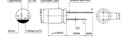
Dimensions
Silvered lead Wire
Capacitance Lot. No. Laminated Case
Type numbering system (Example : 4V 680µF)
1 2 3 4 5 6 7 8 9 10 11 12 13 14
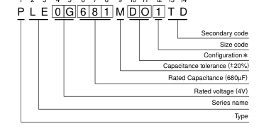
Voltage
| V | 2.5 | 4 | 6.3 |
| Code | e | g | j |
Configuration
(mm)
| φD × L | Code |
| 8 × 9 | CO |
| 8 × 12 | DO |
| 10 × 13 | DO |
| Size | φ8 × 9L | φ8 × 12L | φ10 × 13L |
| φD | 8.0 | 8.0 | 10.0 |
| L | 8.5 | 11.5 | 12.5 |
| P | 3.5 | 3.5 | 5.0 |
| φd | 0.6 | 0.6 | 0.6 |
Standard ratings
| Rated Voltage (V) | Rated Capacitance (µF) | Case Size φD × L (mm) | tan δ | Leakage Current (µA) | ESR (mΩ) (20˚C / 100kHz) | Rated ripple (mArms) (105˚C / 100kHz) | Code |
| 2.5 | 560 | 8 × 9 | 0.08 | 280 | 5 | 6000 | PLE0E561MCO1 |
| 820 | 8 × 9 | 0.08 | 410 | 5 | 6300 | PLE0E821MCO6 | |
| 820 | 8 × 12 | 0.08 | 410 | 5 | 6600 | PLE0E821MDO1 | |
| 1000 | 10 × 13 | 0.08 | 500 | 5 | 7100 | PLE0E102MDO1 | |
| 1500 | 10 × 13 | 0.08 | 750 | 5 | 7300 | PLE0E152MDO1 | |
| 4 | 560 | 8 × 9 | 0.08 | 448 | 5 | 6000 | PLE0G561MCO1 |
| 680 | 8 × 12 | 0.08 | 544 | 5 | 6500 | PLE0G681MDO1 | |
| 820 | 10 × 13 | 0.08 | 656 | 5 | 7000 | PLE0G821MDO1 | |
| 1200 | 10 × 13 | 0.08 | 960 | 5 | 7200 | PLE0G122MDO1 | |
| 6.3 | 470 | 8 × 12 | 0.08 | 592 | 5 | 6400 | PLE0J471MDO1 |
| 680 | 10 × 13 | 0.08 | 857 | 5 | 6700 | PLE0J681MDO1 | |
| 820 | 10 × 13 | 0.08 | 1033 | 5 | 6800 | PLE0J821MDO1 |
: In this case, 6 will be put at 12th digit of type numbering system.
Design, Specifications are subject to change without notice.
Printed in Japan T.2006.I.1C