
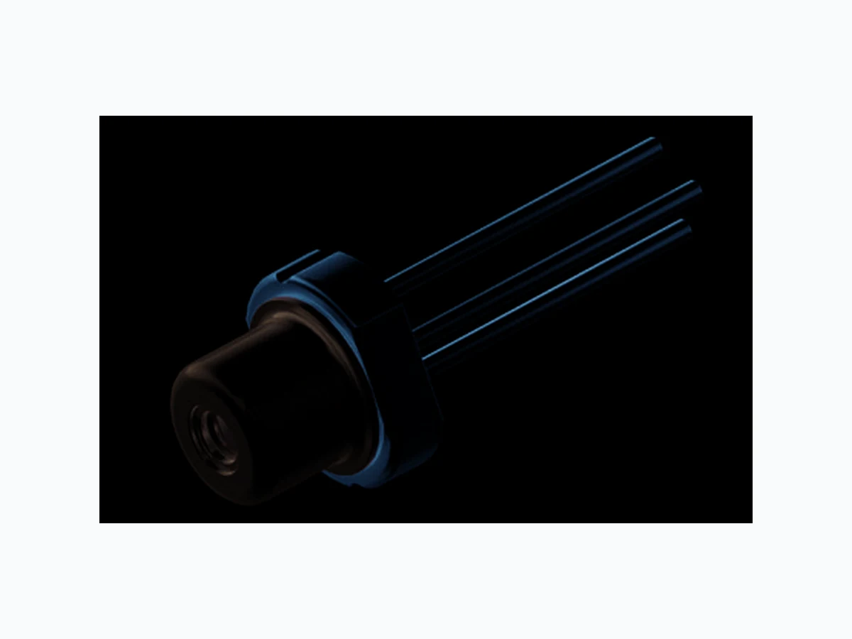
PL520B OSRAM
Document overview
- Manufacturer or author: Provided By www.digicamel.com(FREE DATASHEET DOWNLOAD SITE)
- PDF pages: 7
Technical content
Features
- Optical output power (continuous wave): 80 mW (Tcase = 25 °C)
- Typical emission wavelength: 520 nm
- Efficient radiation source for cw and pulsed operation
- Single transverse mode semiconductor laser
- High modulation bandwidth
- Miniaturized TO38 ICut package
- Laser diode isolated against package
Applications
- Laser projection
- Laser shows
- Biomedical Applications
- Metrology Safety Advice Depending on the mode of operation, these devices emit highly concentrated visible light which can be hazardous to the human eye. Products which incorporate these devices have to follow the safety precautions found in IEC 60825-1 “Safety of laser products”.
16.11.2015 2 DRAFT - This design is for Reference only. Subject to change without notice. Version 0.2 PL 520B
Ordering Information
Operation outside these conditions may damage the device. Operation at maximum ratings may influence lifetime. Laser Characteristics (Tcase = 25 °C) Type: Optical Output Power Ordering Code Popt (Tcase = 25°C) PL 520B 80 mW Q65111A7290 Parameter Symbol Values Unit min. max. Operating Current IF 300 mA Operating Temperature Tcase -20 +60 °C Storage Temperature Tstg -40 +85 °C Reverse Voltage VR 2V Soldering Temperature max. 10 sec. Tsolder 260 °C Junction temperature Tj 120 °C Parameter Symbol Values Unit min. typ. max. Emission Wavelength 1) 1) Standard operating conditions refer to a continuous wave output power of Popt = 80 mW. λpeak 515 520 530 nm Spectral Width (FWHM) 1) Δλ –2– n m Threshold Current Ith –4 0 7 0 m A Operating Current 1) IF – 200 240 mA Operating Voltage 1) VF –6 . 4 8 . 0 V Beam Divergence (FWHM) 1) θ∥ x 5.0 x 18.0 6.3 x 22.5 7.5 x 25.0 deg Polarization 1) Pgr – 100:1 – Modulation Frequency f – >100 – MHz Thermal resistance (junction to case) Rth –3 8– K / W
Version 0.2 PL 520B 16.11.2015 3 DRAFT - This design is for Reference only. Subject to change without notice. Optical Output Power Popt = ƒ (IF) Operating Voltage VF = ƒ (IF) Threshold Current Ith = ƒ (Tcase) Relative Spectral Emission Popt = ƒ (λ) 0 50 100 150 200 250 100 Popt [mW] IF [mA] Tcase=6 0° C Tcase=4 0° C Tcase=2 0° C Tcase=0° C 0 50 100 150 200 250 VF [V] IF [A] Tcase=6 0° C Tcase=4 0° C Tcase=2 0° C Tcase=0° C 0 2 04 06 0 Ith [mA] Tcase [°C] 516 518 520 522 524 0.0 0.2 0.4 0.6 0.8 1.0 Popt [a. u.] /s61548 [nm] Tcase=2 0° C Tcase=4 0° C Tcase=6 0° CTcase=2 0° C Tcase=4 0° C
16.11.2015 4 DRAFT - This design is for Reference only. Subject to change without notice. Version 0.2 PL 520B Beam Divergence Popt = ƒ (θ), Tcase = 25 °C Maximum recommended operating current IF = ƒ (Tcase) -40 -20 0 20 40 0.0 0.2 0.4 0.6 0.8 1.0 /s61553 || /s61553 ⊥ Popt [a. u.] /s61553 [deg] 20 30 40 50 60 210 220 230 240 IF [mA] Tcase [°C]
Version 0.2 PL 520B 16.11.2015 5 DRAFT - This design is for Reference only. Subject to change without notice. Package Outline Dimensions in mm Pin Connection Pin 1: LD Anode Pin 2: Case Pin 3: LD Cathode
16.11.2015 6 DRAFT - This design is for Reference only. Subject to change without notice. Version 0.2 PL 520B Disclaimer OSRAM OS assumes no liability whatsoever for any use of this document or its content by recipient including, but not limited to, for any design in activities based on this preliminary draft version. OSRAM OS may e. g. decide at its sole discretion to stop developing and/or finalizing the underlying design at any time. Attention please! The information describes the type of component and shall not be considered as assured characteristics. Terms of delivery and rights to change design reserv ed. Due to technical requirements components may contain dangerous substances. For information on the types in question please contact our Sales Organization. If printed or downloaded, please find the latest version in the Internet. Packing Please use the recycling operators known to you. We can also help you – get in touch with your nearest sales office. By agreement we will take packing materi al back, if it is sorted. You must be ar the costs of transport. For packing material that is returned to us unsorted or which we are not obliged to accept, we shall have to invoice you for any costs incurred. Components used in life-support devices or systems must be expressly authorized for such purpose! Critical components* may only be used in life-suppo rt devices** or systems with the express written approval of OSRAM OS. *) A critical component is a componen t used in a life-su pport device or system whose failure can reasonably be expected to cause the failure of that life-support device or system, or to affect its safety or the effectiveness of that device or system. **) Life support devices or systems are intended (a) to be implanted in the human body , or (b) to support and/or maintain and sustain human life. If they fa il, it is reasonable to assume that the health and the life of the user may be endangered. Important notes of operation for laser diode a) Electrical operation OSRAMs laser diodes are designed for maximum performance and reliability. Operating the laser diode above the maximum rating even for very short periods of time can damage the laser diode or reduce its lifetime. The laser diode must be operated with a suitable power supply with minimized electrical noise. The laser diode is very sensitive to electrostatic discharge (ESD). Proper precautions must be taken. b) Mounting instructions In order to maintain the lifetime of the laser diode proper heat management is essential. Due to the design of the laser diode heat is dissipated only through the base plate of the diode‘s body. A proper heat conducting interconnection between the diodes base plate and the heat sink must be maintained.
Version 0.2 PL 520B 16.11.2015 7 DRAFT - This design is for Reference only. Subject to change without notice. Published by OSRAM Opto Semiconductors GmbH Leibnizstraße 4, D-93055 Regensburg www.osram-os.com © All Rights Reserved. Eu RoHS compliant product