


 Download PDF
PFVS SCHURTER
Document overview
- PDF pages: 2
Technical content
Page 1
FUSES Resettable fuses
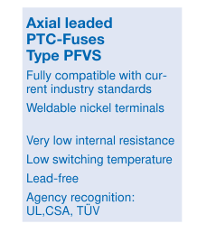
Pb
50 75 100
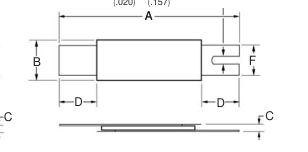
Dimensions
SLIT 0.5 x 4.0
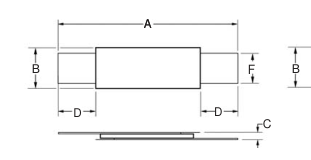
(.020) (.157)
PFVS
Typical Time to Trip at 23 ˚C
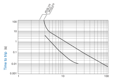
Fault current (A)
Nominal
Applications
- Any application that requires protection at low resistances
- Rechargeable battery packs
- Cellular phones
- Laptop computers
Environmental Characteristics Operating/Storage Temperature / Einsatz/Lagertemp.
–40 °C to +85 °C
Maximum Device Surface Temperature in Tripped State / 125 °C
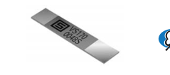
Typical Part Marking Layout may vary
Manufacturer’s Trademark
Part identification n
Date code (First digit = Last digit of
Lot No. (T = Taiwan, S = Xiamen)
year; next three digits = day of year)
+60 °C, 1000 hours / Std.
Passive Aging / passive Alterung
± 10% typ. resist. change
+60 °C, 85% R.H. 1000 hours / Std. ± 10% typ. resist. change
Humidity Aging / Feuchtigkeitsalterung
MIL-STD-202F, Method 107G
Thermal Shock / Thermischer Schock )
± 5% typ. resist. change
+85 °C/–40 °C 10 times
Vibration
MIL-STD-883C,
No change
Condition A
Test Procedures And Requirements For Model PFVS Series Test / Test
Test Conditions / Bedingungen
Accept/Reject Criteria
Verify dimensions and materials / Kontrolle Abmess./Mat. Per MF physical description
Visual/Mech. / visuell/mech. Resistance / Widerstand
In still air @ 23 °C / bei ruhiger Luft 23 °C
Rmin ≤ R ≤ Rmax
At specified current, Vmax 23 °C / Bei entsprech. Strom
Time to Trip / Trip-Zeit Hold Current / Haltestrom
30 min. at Ihold / bei Haltestrom
Trip Cycle Life / Trip-Zyklen
Vmax, Imax, 100 cycles / Zyklen
Trip Endurance / Zeit im Tripzustand Vmax, 48 hours / Stunden
www.schurter.com
T ≤ max. time to trip (sec.) No trip No arcing or burning No arcing or burning
Page 2
FUSES / SICHERUNGEN
PFVS
Resettable fuses
Electrical Characteristics
| Type / Typ | V max Volts | I max Amps | I hold | I trip | Initial Resistance / | One Hour Post-Trip Restistance / | Max. Time to trip / | Tripped Power Dissipation / | ||
|---|---|---|---|---|---|---|---|---|---|---|
| Amperes at / bei 23 °C | Ohms at / bei 23 °C | Ohms at / bei 23 °C | Amperes at / bei 23 °C | Seconds at / bei 23 °C | Watts at / bei 23 °C | |||||
| Hold | Trip | Min. | Max. | Max. | ||||||
| PFVS.170 | 16 | 100 | 1.7 | 3.4 | 0.030 | 0.052 | 0.105 | 8.5 | 3 | 1.4 |
| PFVS.210 | 16 | 100 | 2.1 | 4.7 | 0.018 | 0.030 | 0.060 | 10 | 5 | 1.5 |
Dimensions
| Model / Modell | A | B | C | D | F | Pkg. Style | |||||
| min. | max. | min. | max. | min. | max. | min. | max. | min. | max. | ||
| PFVS.170 | 16.0 (0.630) | 18.5 (0.728) | 4.9 (0.193) | 5.3 (0.209) | 0.6 (0.024) | 0.8 (0.031) | 4.1 (0.161) | 5.8 (0.228) | 3.9 (0.154) | 4.1 (0.161) | Std. |
| PFVS.170.S | 16.0 (0.630) | 18.5 (0.728) | 4.9 (0.193) | 5.3 (0.209) | 0.6 (0.024) | 0.8 (0.031) | 4.1 (0.161) | 5.8 (0.228) | 3.9 (0.154) | 4.1 (0.161) | S |
| PFVS.210 | 20.9 (0.823) | 23.7 (0.933) | 4.9 (0.193) | 5.3 (0.209) | 0.6 (0.024) | 0.8 (0.031) | 4.1 (0.161) | 5.8 (0.228) | 3.9 (0.154) | 4.1 (0.161) | Std. |
| PFVS.210.L | 24.0 (0.945) | 26.5 (1.043) | 4.9 (0.193) | 5.3 (0.209) | 0.6 (0.024) | 0.8 (0.031) | 5.0 (0.197) | 7.1 (0.280) | 3.9 (0.154) | 4.1 (0.161) | Std. |
| PFVS.210.S | 20.9 (0.823) | 23.7 (0.933) | 4.9 (0.193) | 5.3 (0.209) | 0.6 (0.024) | 0.8 (0.031) | 4.1 (0.161) | 5.8 (0.228) | 3.9 (0.154) | 4.1 (0.161) | S |
Dimensions in mm/inches
Packaging
How To Order
All models packaged in bulk, 500 pieces each.
PF VS .xxx .x
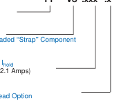
PTC-Fuse
Series VS = Axial Leaded “Strap” Component
Hold Current, Ihold 170-210 (1.7-2.1 Amps)
Lead Option S = Slotted Lead Option L = Longer Lead Option
Thermal Derating Chart-Ihold (Amps)
| Type / Typ | Ambient Operating Temperature | ||||||||
|---|---|---|---|---|---|---|---|---|---|
| –40 ˚C | –20 ˚C | 0 ˚C | 23 ˚C | 40 ˚C | 50 ˚C | 60 ˚C | 70 ˚C | 85 ˚C | |
| PFVS.170 | 3.2 | 2.7 | 2.2 | 1.7 | 1.3 | 1.1 | 0.8 | 0.6 | 0.1 |
| PFVS.170.S | 3.2 | 2.7 | 2.2 | 1.7 | 1.3 | 1.1 | 0.8 | 0.6 | 0.1 |
| PFVS.210 | 4.1 | 3.5 | 2.9 | 2.1 | 1.6 | 1.3 | 1.0 | 0.7 | 0.1 |
| PFVS.210.L | 4.1 | 3.5 | 2.9 | 2.1 | 1.6 | 1.3 | 1.0 | 0.7 | 0.1 |
| PFVS.210.S | 4.1 | 3.5 | 2.9 | 2.1 | 1.6 | 1.3 | 1.0 | 0.7 | 0.1 |
www.schurter.com