
 Download PDF
PFS1200-12-054XA BEL
Document overview
- PDF pages: 28
Technical content
Page 1

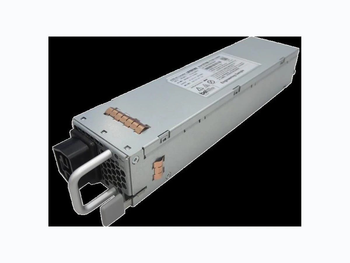
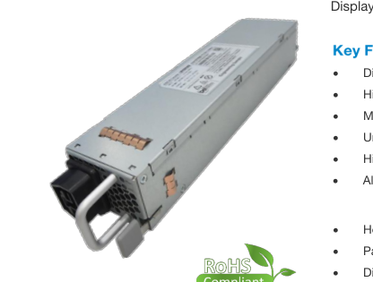
The PFS1200-12-054xA is a 1200 Watt AC to DC power-factorcorrected (PFC) power supply that converts standard AC or HVDC power into a main output of 12 VDC for powering intermediate bus architectures (IBA) in high performance and reliability servers, routers, and network switches.
Displays the CE-Mark for the European Low Voltage Directive (LVD).
Digital inrush current control
High Efficiency
Meets 80Plus Platinum efficiency requirement
Universal input voltage range: 90 – 305 VAC
High voltage DC input: 180 – 400 VDC
Always-On standby output (model dependent): o 3.3 V o Programmable 5 V / 12 V Hot-plug capable
Parallel operation with active current sharing
Digital controls for improved performance
- High density design: 39 W/in3
- Small form factor (WxHxL): 54.5 x 40 x 228.6 mm (2.15 x 1.57 x 8.98 in)
- I2C communication interface for control, programming and monitoring with Power Management Bus protocol and PSMI Protocol
- Over temperature, output over voltage and overcurrent protection
- 256 Bytes of EEPROM for user information
- 2 Status LEDs: OK and FAIL with fault signaling
- High Performance Servers
- Routers
- Switches

Page 2
2
PFS
1200
- 12 - 054
Product Family Power Level Dash V1 Output Dash Width
PFS Front-Ends 1200 W
12 V
54 mm
1 N = Normal Airflow from Output connector to Input AC socket; R = Reverse Airflow from Input AC socket to Output connector 2
x
A
x
Airflow 1
Input
Options blank: C14 Socket 2
N: Normal
C: C16 Socket 2
A: AC Input
R: Reverse
H: HVDC Socket 3
C14 / C16 AC input connector, input range 90 ~ 264 VAC and 180 ~ 350 VDC 3 Ordering PN: PFS1200-12-054xAH for both AC and HVDC (Anderson 2006G1-BK) input connector, input range is 180 ~ 400 VDC and 90 ~ 305 VAC
The PFS1200-12-054xA AC/DC power supply is with DSP control, high efficient front-end power supply. It incorporates resonancesoft-switching technology and interleaved power trains to reduce component stresses, providing increased system reliability and very high efficiency. With a wide input operational voltage range and minimal derating of output power with input voltage and temperature, the PFS1200-12-054xA power supply maximizes power availability in demanding server, network, and other high availability applications. The supply is fan cooled and ideally suited for integration with a matching airflow paths. Both the PFC stage and DC/DC stage is with DSP control. The DC/DC stage uses soft switching resonant techniques in conjunction with synchronous
rectification. An active OR-ing device on the output ensures no reverse load current and renders the supply ideally suited for operation in redundant power systems. The always-on standby output, provides power to external power distribution and management controllers. It is protected with an active OR-ing device for maximum reliability. Status information is provided with front-panel LEDs. In addition, the power supply can be controlled and the fan speed set via the I2C bus. The I2C bus allows full monitoring of the supply, including input and output voltage, current, power, and inside temperatures. The fan speed is adjusted automatically depending on the actual power demand and supply temperature and can be overridden through the I2C bus.
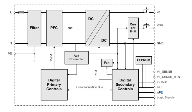
Figure 1. PFS1200-12-054NAH Series Block Diagram

Page 3
3
Stresses in excess of the absolute maximum ratings may cause performance degradation, adversely affect long-term reliability, and cause permanent damage to the supply.
Vi maxc Maximum Input
Continuous
90
305 VAC
General Condition: TA = 0… 50°C unless otherwise specified.
100 115/230 277 VAC
Vi nom Nominal Input Voltage
3801
200
VDC
Vi Input Voltage Ranges
Normal operating (Vi min to Vi max)
90
305 VAC
400
180
VDC
Ii max Max Input Current
16 Arms
Ii p Inrush Current Limitation
Vi min to Vi max, TNTC = 25°C(Figure 2)
60 Ap
Fi Input Frequency
47 50/60 63 Hz
PF Power Factor
Vi nom, 50 Hz, > 0.3 I1 nom
0.94
W/VA
74
84 VAC
Turn-on Input Voltage2 Vi on
Ramping up
170
180 VDC

Vi115VAC, 0.2∙Ix nom, Vx nom, TA = 25°C
90
Vi115 VAC, 0.5∙Ix nom, Vx nom, TA = 25°C
92
Vi 115 VAC, Ix nom, Vx nom, TA = 25°C
89
η Efficiency
Vi 230VAC, 0.2∙Ix nom, Vx nom, TA = 25°C
90
Vi 230VAC, 0.5∙Ix nom, Vx nom, TA = 25°C
94
Vi 230VAC, Ix nom, Vx nom, TA = 25°C
91
Vi = 90Vac to 264Vac,V1 ≥ 11.4 V, Cout = 5000 µF, 80% nominal output power, Time from de-
Thold Hold-up Time
5
ms
assert INPUT_OK to Vout out of regulation or OUTPUT_OK de-asserts
1 For PFS1200-12-054NA/ PFS1200-12-054NAC and PFS1200-12-054RA/ PFS1200-12-054RAC, normal DC operation input range is 200 VDC to 350 VDC; normal AC operation input range is 100 VAC ~ 240 VAC. 2 The Front-End is provided with a minimum hysteresis of 3 V during turn-on and turn-off within the ranges.

Page 4
4
4.1 INPUT FUSE
Slow-acting 16 A input fuse (5 x 20 mm) in series the L line inside the power supply protect against severe defects. The fuse Is not accessible from the outside and are therefore not serviceable parts.
4.2 INRUSH CURRENT
The AC-DC power supply exhibits low X-capacitance resulting in a low and short peak current, when the supply is connected to the mains. The internal bulk capacitor will be charged through an NTC which will limit the inrush current.
NOTE: Do not repeat plug-in / out operations within a short time, or else the internal in-rush current limiting device (NTC) may not sufficiently cool down and excessive inrush current or component failure(s) may result.
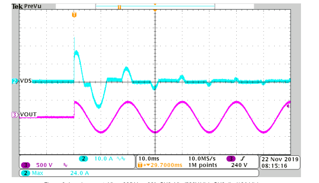
Figure 2. Inrush current, Vin = 305 Vac, 90°, CH3: Vin (500V/div), CH2: Iin (10A/div)
4.3 INPUT UNDER-VOLTAGE
If the sinusoidal input voltage stays below the input under voltage lockout threshold Vi on, the supply will be inhibited. Once the input voltage returns within the normal operating range, the supply will return to normal operation again.
4.4 POWER FACTOR CORRECTION
Power factor correction (PFC) is achieved by controlling the input current waveform synchronously with the input voltage. An analog controller is implemented giving outstanding PFC results over a wide input voltage and load ranges. The input current will follow the shape of the input voltage.

Page 5
5
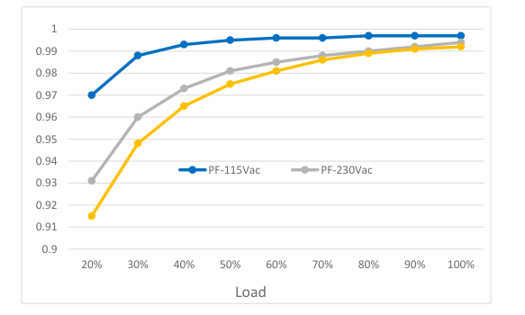
Figure 3. PF vs. Load
4.5 EFFICIENCY
High efficiency is achieved by using state-of-the-art silicon power devices in conjunction with soft-transition topologies minimizing switching losses and a full digital control scheme. Synchronous rectifiers on the output reduce the losses in the high current output path. The speed of the fan is digitally controlled to keep all components at an optimal operating temperature regardless of the ambient temperature and load conditions.
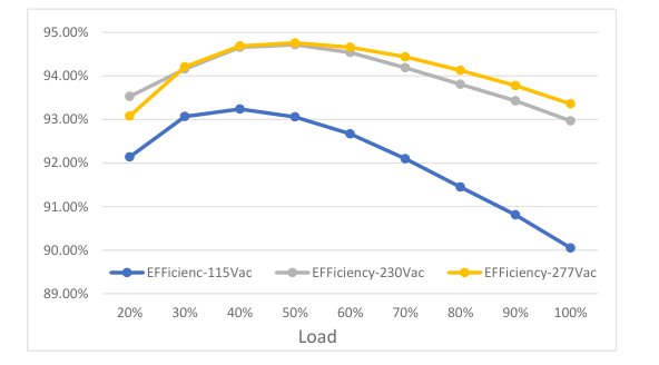
Figure 4. Efficiency vs. Load

Page 6
6
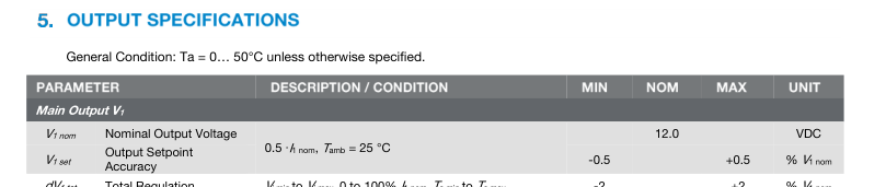
dV1 tot Total Regulation
Vi min to Vi max,0 to 100% I1 nom,Ta min to Ta max
-2
+2 % V1 nom
305 VAC > Vin ≥ 90 VAC, V1 = 12 VDC
P1 nom Nominal Output Power
1200
W
Refer to Figure 6b for
400 VDC > Vin ≥180 VDC, V1 = 12 VDC
1200
W
derating curves
305 VAC > Vin ≥ 90 VAC, V1 = 12 VDC
I1 nom Nominal Output Current
100
ADC
Refer to Figure 3b/3c for
400 VDC > Vin ≥180 VDC, V1 = 12 VDC
100
ADC
derating curves
V1 nom, 0 to100%I1 nom, 20 MHz BW (See Section 5.1)
v1 pp Output Ripple Voltage
120 mVpp
dV1 Load Load Regulation
Vi = Vi nom, 0 - 100 % I1 nom
80
mV

Trec Recovery Time
2 ms
dI1/dt = 1A/μs, recovery within 1% of V1 nom
tAC V1 Start-up Time from AC
3 sec
tV1 rise Rise Time
V1 = 10…90% V1 nom
0.5
10 ms

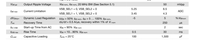
dVSB tot Total Regulation
Vi min to Vi max,0 to 100% ISB nom,Ta min to Ta max
-5
+5 %VSBnom
VSB = 3.3 VDC,
16.5
PSB nom Nominal Output Power
W
VSB = 5.0 VDC,
16.5
VSB = 3.3 VDC,
5
ISB nom Nominal Output Current
ADC
VSB = 5.0 VDC,
3.3

Page 7
7
5.1 OUTPUT VOLTAGE RIPPLE
Internal capacitance at the 12 V output (behind the OR-ing circuitry) is minimized to prevent disturbances during hot plug. In order to provide low output ripple voltage in the application, external capacitors (a parallel combination of 10 µF low ESR capacitor in parallel with 0.1 µF ceramic capacitors) should be added close to the power supply output. The setup of Figure has been used to evaluate suitable capacitor types.
Table 1 and Table 2 should be used to reduce the output ripple voltage. The ripple voltage is measured with 20 MHz BWL, close to the external capacitors.
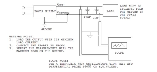
Figure 5. Output ripple test setup
NOTE: Care must be taken when using ceramic capacitors with a total capacitance of 1 µF to 50 µF on output V1, due to their high quality factor the output ripple voltage may be increased in certain frequency ranges due to resonance effects.
EXTERNAL CAPACITOR V1
DV1MAX UNIT
Standard test condition: 1 Pc 10 µF / min 16 V low ESR Capacitor
120 mVpp
1 pc 0.1 µF / 50 V ceramic capacitor
Table 1. Suitable capacitors for V1
EXTERNAL CAPACITOR VSB
DV1MAX UNIT
Standard test condition: 1 pc 10 µF / min 16 V low ESR Capacitor
120 mVpp
1 pc 0.1 µF / 50V ceramic capacitor
Table 2. Suitable capacitors for VSB
The output ripple voltage on VSB is influenced by the main output V1. Evaluating VSB output ripple must be done when maximum load is applied to V1.

Page 8
8

V1 OV OV Threshold V1
13.3
14.5 VDC
tOV V1 OV Latch Off Time V1
1 ms
VSB OV OV Threshold VSB
110%
120% VDC
tOV VSB OV Latch Off Time VSB
1
ms
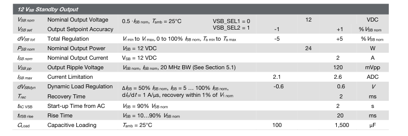
IV1 lim Over Current Limitation V1
Vi > 90 VAC, Ta < 50°C
110
140 A
Ta < 50°C for 12VSB
2.1
2.6
IVSB lim Over Current Limitation VSB
Ta < 50°C for 5VSB
3.45
4.3 A
Ta < 50°C for 3.3VSB
5.25
6.5
tV1 SC Short Circuit Regulation Time
V1 < 3 V, time until IV1 is limited to < 200 A
2 ms
TSD Over Temperature on Heat Sinks
Automatic shut-down
115 120 °C
6.1 OVERVOLTAGE PROTECTION
The PFS front-ends provide a fixed threshold overvoltage (OV) protection implemented with a HW comparator. Once an OV condition has been triggered, the supply will shut down and latch the fault condition. The latch can be unlocked by disconnecting the supply from the AC mains or by toggling the PSON_L input
6.2 UNDERVOLTAGE DETECTION
Both main and standby outputs are monitored. LED and PWOK_L pin signal if the output voltage exceeds ±7% of its nominal voltage. Output under voltage protection is provided on both outputs. When either V1 or VSB falls below 93% of its nominal voltage, the output is inhibited.
6.3 CURRENT LIMITATION
6.3.1 MAIN OUTPUT
When main output runs in current limitation mode its output will turn OFF below 2 V but will shut down after 6 attempts. If current limitation mode is still present after the unit retry, output will continuously perform this routine until current is below the current limitation point. The supply will go through soft start every time it retries from current limitation mode.
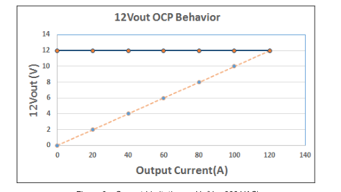
Figure 6a. Current Limitation on V1 (Vi = 230 VAC)

Page 9
9
The output power derating of V1 refers to Figure 6b Ambient Derating Curve.
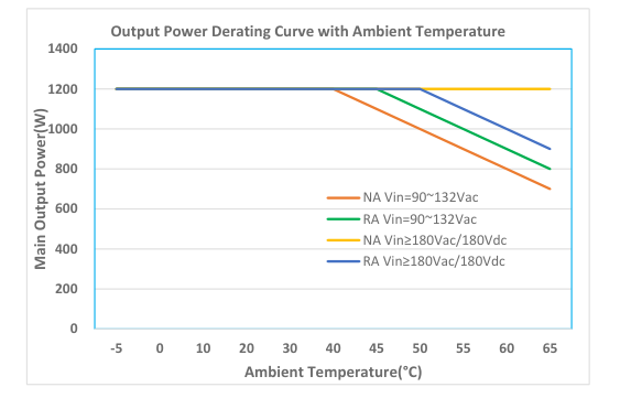
Figure 6b.Ambient Derating Curve
Note: 1. NA: Normal Airflow RA: Reverse Airflow Refer to Figure 21. 2. The application of power supply should also refer to installation instructions document 3. The power supply has no limitation on its output current/power in the respect of meeting the operating conditions shown by the derating limits shown above. It is the responsibility of the end user to ensure operating conditions are maintained within their safety agency certification limits to assure safe and reliable operation.
6.3.2 STANDBY OUTPUT
3.3 / 5 VSB
The standby output exhibits a substantially rectangular output characteristic down to 0 V (no hiccup mode / latch off). If it runs in current limitation and its output voltage drops below the UV threshold, then the main output will be inhibited (standby remains on). The current limitation of the standby output is independent of the AC input voltage.
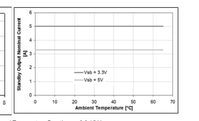
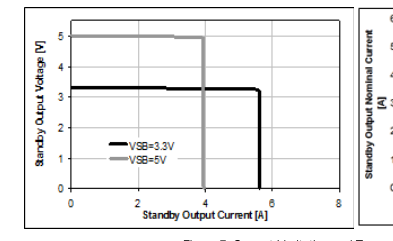
Figure 7. Current Limitation and Temperature Derating on 3.3 / 5 VSB

Page 10
10
12 VSB
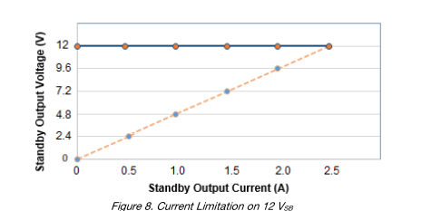
On the standby output, a hiccup type over current protection is implemented. This protection will shut down the standby output immediately when standby current reaches or exceeds IVSB lim. After an off-time of 1 s the output automatically tries to restart. If the overload condition is removed the output voltage will reach again its nominal value. At continuous overload condition the output will repeatedly trying to restart with 1s intervals. A failure on the Standby output will shut down both Main and Standby outputs.
PARAMETER DESCRIPTION / CONDITION
MIN NOM MAX
UNIT
Vi min ≤ Vi ≤ Vi max
Vi mon
Input RMS Voltage
-2.5
+2.5 %
Ii mon
Input RMS Current
Ii > 2 Arms
-5
+5 %
Pi mon
True Input Power
Ii > 2 Arms
-5
+5 %
V1 mon
V1 Voltage
-2
+2 %
I1 > 25 A
-2
+2 %
I1 mon
V1 Current
I1 ≤ 25 A
-1
+1 A
Po > 120 W
-5
+5 %
Po nom
Total Output Power
Po ≤ 120 W
-12
+12 W
VSB mon
Standby Voltage
-0.5
+0.5 V
ISB ≤ ISB nom
ISB mon
Standby Current
-0.5
+0.5 A

Page 11
11

VIH
Input High Level Voltage
2.4
3.5 V
IIL, H
Maximum Input Sink or Source Current
0
1 mA
kΩ
RpuPSKILL_H
Internal Pull Up Resistor on PSKILL_H
20
kΩ
RpuPSON_L
Internal Pull Up Resistor on PSON_L
10
kΩ
RpuHOTSTANDBYEN_H Internal Pull Up Resistor on HOTSTANDBYEN_H
2
kΩ
RLOW
Resistance Pin to SGND for Low Level
0
1
kΩ
RHIGH
Resistance Pin to SGND for High Level
50
PWOK_H Output
VOL
Output Low Level Voltage
Isink < 4 mA
0
0.4 V
VOH
Output High Level Voltage
Isource < 0.5 mA
2.6
3.5 V
kΩ
RpuPWOK_H
Internal Pull Up Resistor on PWOK_H
1
ACOK_H Output
VOL
Output Low Level Voltage
Isink < 2 mA
0
0.4 V
VOH
Output High Level Voltage
Isource < 50 µA
2.6
3.5 V
kΩ
RpuACOK_H
Internal Pull Up Resistor on ACOK_H
1
SMB_ALERT_L Output
Vext
Maximum External Pull Up Voltage
12 V
VOL
Output Low Level Voltage
Isource < 4 mA
0
0.4 V
IOH
Maximum High Level Leakage Current
10 µA
Internal Pull Up Resistor on
kΩ
RpuSMB_ALERT_L
None
SMB_ALERT_L
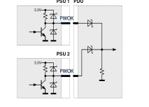
8.2 INTERFACING WITH SIGNALS
All signal pins have protection diodes implemented to protect internal circuits. When the power supply is not powered, the protection devices start clamping at signal pin voltages exceeding ±0.5 V. Therefore, all input signals should be driven only by an open collector/drain to prevent back feeding inputs when the power supply is switched off. If interconnecting of signal pins of several power supplies is required, then this should be done by decoupling with small signal schottky diodes except for SMB_ALERT_L, ISHARE and I2C pins. SMB_ALERT_L pins can be interconnected without decoupling diodes, since these pins have no internal pull up resistor and use a 15 V zener diode as protection device against positive voltage on pins. ISHARE pins
must be interconnected without any additional components. This in-/output is disconnected from internal circuits when the power supply is switched off.
PSU 1 PDU
PSU 1 PDU
3.3V
VSB_SEL
PSU 2 3.3V
VSB_SEL
Figure 9. Interconnection of Signal Pins

Page 12
12
8.3 FRONT LEDS
There will be 2 Bi-color (Green/ Amber) LED to indicate power supply status. The LED are visible on the power supply’s exterior face. The LED location meets ESD Requirements. Following are these definitions as:
LED FUNCTION
Input AC
Output DC/Fault
COMMAND NAME
CONDITION
VOUT (V)
VOUT Normal Operation
12.00
VOUT_OV_FAULT_LIMIT
0.00
VOUT_OV_WARN_LIMIT
13.5
VSTBY_OV_FAULT_LIMIT
12.00
VSTBY_OV_WARN_LIMIT
12.00
VOUT_UV_FAULT_LIMIT
0.00
VOUT_UV_WARN_LIMIT
11.40
VSTBY_UV_FAULT_LIMIT
12.00
VSTBY_UV_WARN_LIMIT
12.00
IOUT_OC_FAULT_LIMIT
0.00
IOUT_OC_WARN_LIMIT
12.00
ISTBY_OC_FAULT_LIMIT
12.00
ISTBY_OC_WARN_LIMIT
12.00
TEMPERATURE WARNING LIMIT
12.00
TEMPERATURE FAULT LIMIT
0.00
VIN_OV_FAULT_LIMIT
0.00
VIN_OV_WARN_LIMIT
12.00
VIN_UV_FAULT_LIMIT
0.00
VIN_UV_WARN_LIMIT
12.00
IIN_OC_FAULT_LIMIT
0.00
IIN_OC_WARN_LIMIT
12.00
FAN_1_FAULT
0.00
FAN_1_WARNING
12.00
IOUT SHORT CIRCUIT
0.00
ISTBY SHORT CIRCUIT
12.00
PS_ON High
0.00
PS_Kill
0.00
COLOR
BRIGHTNESS
Green (520 nm – 540 nm)
500-1000cd/m^2
Green (520 nm – 540 nm) / Amber (520 nm – 540 nm)
500-1000cd/m^2
Amber (587 nm – 595 nm)
OUTPUT VOLTAGE STATUS
LED BEHAVIOR COLOR/BLINKING/SOLID/OFF
VSTBY (V)
INPUT
OUTPUT/FAULT
3.3/5.0/12.0
GREEN SOLID
GREEN SOLID
3.3/5.0/12.0
GREEN SOLID
AMBER SOLID
3.3/5.0/12.0
GREEN SOLID
AMBER BLINKING
0.00
GREEN SOLID
AMBER SOLID
3.7/5.6/13.5
GREEN SOLID
AMBER BLINKING
3.3/5.0/12.0
GREEN SOLID
AMBER SOLID
3.3/5.0/12.0
GREEN SOLID
AMBER BLINKING
0.00
GREEN SOLID
AMBER SOLID
3.0/4.5/11.0
GREEN SOLID
AMBER BLINKING
3.3/5.0/12.0
GREEN SOLID
AMBER SOLID
3.3/5.0/12.0
GREEN SOLID
AMBER BLINKING
0.00
GREEN SOLID
AMBER SOLID
3.3/5.0/12.0
GREEN SOLID
AMBER BLINKING
3.3/5.0/12.0
GREEN SOLID
AMBER BLINKING
3.3/5.0/12.0
GREEN SOLID
AMBER SOLID
3.3/5.0/12.0
GREEN BLINKING
AMBER SOLID
3.3/5.0/12.0
GREEN BLINKING
AMBER BLINKING
0.00
OFF
OFF
3.3/5.0/12.0
GREEN BLINKING
AMBER BLINKING
3.3/5.0/12.0
GREEN SOLID
AMBER SOLID
3.3/5.0/12.0
GREEN SOLID
AMBER BLINKING
3.3/5.0/12.0
GREEN SOLID
AMBER SOLID
3.3/5.0/12.0
GREEN SOLID
AMBER BLINKING
3.3/5.0/12.0
GREEN SOLID
AMBER SOLID
0.00
GREEN SOLID
AMBER SOLID
3.3/5.0/12.0
GREEN SOLID
GREEN BLINKING
0.00
GREEN SOLID
OFF
Table 3. LED Status

Page 13
13
8.4 PRESENT_L
This signaling pin is recessed within the connector and will contact only once all other connector contacts are closed. This active-low pin is used to indicate to a power distribution unit controller that a supply is plugged in. The maximum current on PRESENT_L pin should not exceed 10 mA.
PFE PDU
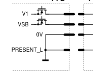
Figure 10. PRESENT_L signal pin
8.5 PSKILL_H INPUT
The PSKILL_H input is active-high and is located on a recessed pin on the connector and is used to disconnect the main output as soon as the power supply is being plugged out. This pin should be connected to SGND in the power distribution unit. The standby output will remain on regardless of the PSKILL_H input state.
8.6 AC TURN-ON / DROP-OUTS / ACOK_H
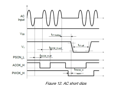
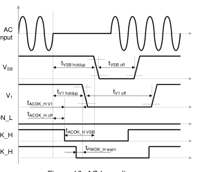
The power supply will automatically turn-on when connected to the AC line under the condition that the PSON_L signal is pulled low and the AC line is within range. The ACOK_H signal is active-high. See the timing diagram, Figure 11 and Table 4.
OPERATING CONDITION
MIN MAX UNIT
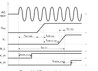
tAC VSB AC Line to 90% VVSB
2 sec
tAC V1 AC Line to 90% V1
2 sec
tACOK_H on1 ACOK_H signal on delay (start-up)
2000 ms
tACOK_H on2 ACOK_H signal on delay (dips)
100 ms
tACOK_H off ACOK_H signal off delay
5 ms
tVSB V1 del VSB to V1 delay
10 500 ms
tV1 holdup Effective V1 holdup time
5 ms
tVSB holdup Effective VSB holdup time
20 ms
tACOK_H V1 ACOK_H to V1 holdup
5 ms PSON_L
tACOK_H VSB ACOK_H to VSB holdup
15 ms ACOK_H
tV1 off Minimum V1 off time
1 2 sec PWOK_H
tVSB off Minimum VSB off time
1 2 sec
NOTE: AC short dips means below 10 ms;
Figure 11. AC turn-on timing
AC long dips means 10 ms to 100 ms
Table 4. AC Turn-on / Dip Timing

Page 14
14
PSON_L
ACOK_H
PWOK_H
Figure 13. AC long dips
8.7 PSON_L INPUT
The PSON_L is an internally pulled-up (3.3 V) input signal to enable/disable the main output V1 of the front-end. This activelow pin is also used to clear any latched fault condition, see the parameters in Table 5.
OPERATING CONDITION
MIN MAX
UNIT
tPSON_L V1on
PSON_L to V1 delay (on)
2 20 ms
tPSON_L V1off
PSON_L to V1 delay (off)
2 20 ms
tPSON_L H min
PSON_L minimum High time
10
ms
Table 5. PSON_L timing
8.8 PWOK_H SIGNAL
The PWOK_H is an open drain output with an internal pull-up to 3.3 V indicating whether both VSB and V1 outputs are within regulation. This pin is active-low. The timing diagram is shown in Figure 14 and referenced in the Table 6.
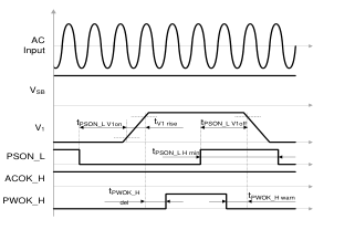
OPERATING CONDITION
MIN MAX UNIT
tPWOK_H del PWOK_H to V1 delay (on)
100 500 ms
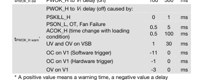
(after fact).
Figure 14. PSON_L and PWOK_H turn-on/off timing
Table 6. PWOK_H timing

Page 15
15
8.9 VSB VOLTAGE SELECTION (VSB_SEL1, VSB_SEL2)
The standby output voltage can be configured to three different values: 3.3V, 5V and 12V by pulling VSB_SEL1 and VSB_SEL2 input pins either to GND (Logic Low) or to 3.3V
VSB_SEL1
VSB_SEL2
VSB Voltage
UNIT
0
0
3.3 V
1
0
5 V
0
1
12 V
1
1
Invalid (Off)
Table 6. VSB Voltage selection
8.10 CURRENT SHARE
The PFS front-ends have an active current share scheme implemented for V1. All the ISHARE current share pins need to be interconnected in order to activate the sharing function. If a supply has an internal fault or is not turned on, it will disconnect its ISHARE pin from the share bus. This will prevent dragging the output down (or up) in such cases.
The current share function uses a analog bi-directional data exchange on a recessive bus configuration to transmit and receive current share information. The controller implements a Master/Slave current share function. The power supply providing the largest current among the group is automatically the Master. The other supplies will operate as Slaves and increase their output current to a value close to the Master by slightly increasing their output voltage. The voltage increase is limited to +250 mV.
The standby output uses a passive current share method (droop output voltage characteristic).
8.11 SENSE INPUTS
Main output has sense lines implemented to compensate for voltage drop on load wires (no sense lines for 12VSB). The maximum allowed voltage drop is 200 mV on the positive rail and 100 mV on the PGND rail.
With open sense inputs the main output voltage will rise by 270 mV. Therefore, if not used, these inputs should be connected to the power output and PGND close to the power supply connector. The sense inputs are protected against short circuit. In this case the power supply will shut down.
8.12 HOT-STANDBY OPERATION
The hot-standby operation is an operating mode allowing to further increase efficiency at light load conditions in a redundant power supply system. Under specific conditions one of the power supplies is allowed to disable its DC/DC stage. This will save the power losses associated with this power supply and at the same time the other power supply will operate in a load range having a better efficiency. In order to enable the hot standby operation, the HOTSTANDBYEN_H and the ISHARE pins need to be interconnected. A power supply will only be allowed to enter the hot-standby mode, when the HOTSTANDBYEN_H pin is high, the load current is low and the supply was allowed to enter the hot-standby mode by the system controller via the
appropriate I2C command (by default disabled). The system controller needs to ensure that only one of the power supplies is allowed to enter the hot-standby mode.
If a power supply is in a fault condition, it will pull low its active-high HOTSTANDBYEN_H pin which indicates to the other power supply that it is not allowed to enter the hot-standby mode or that it needs to return to normal operation should it already have been in the hot-standby mode.
NOTE: The system controller needs to ensure that only one of the power supplies is allowed to enter the hot-standby model.

Page 16
16
PSU 1
PSU 2
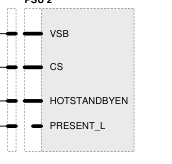
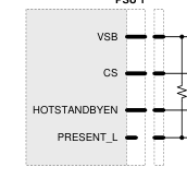
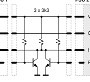
Figure 15. Recommended hot-standby configuration
In order to prevent voltage dips when the active power supply is unplugged while the other is in hot-standby mode, it is strongly recommended to add the external circuit as shown in15. If the PRESENT_L pin status needs also to be read by the system controller, it is recommended to exchange the bipolar transistors with small signal MOS transistors or with digital transistors.
8.13 I2C / SMBUS COMMUNICATION
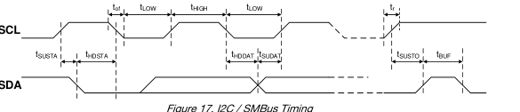
The interface driver in the PFS supply is referenced to the V1 Return. The PFS supply is a communication Slave device only; it never initiates messages on the I2C/SMBus by itself. The communication bus voltage and timing is defined in Table 7 further characterized through:
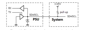
- There are no internal pull-up resistors
- The SDA/SCL IOs are 3.3/5 V tolerant
- Full SMBus clock speed of 100 kbps
- Clock stretching limited to 1 ms
- SCL low time-out of >25 ms with recovery within 10 ms
- Recognizes any time Start/Stop bus conditions
Figure 16. Physical layer of communication interface
The SMB_ALERT_L signal indicates that the power supply is experiencing a problem that the system agent should investigate. This is a logical OR of the Shutdown and Warning events. The power supply responds to a read command on the general SMB_ALERT_L call address 25(0x19) by sending its status register. Communication to the DSP or the EEPROM will be possible as long as the input AC voltage is provided. If no AC is present, communication to the unit is possible as long as it is connected to a life V1 output (provided e.g. by the redundant unit). If only VSB is provided, communication is not possible.
PARAMETER DESCRIPTION / CONDITION
MIN NOM MAX
UNIT
ViL
Input low voltage
-0.5
1.0 V
ViH
Input high voltage
2.3
5.5 V
Vhys
Input hysteresis
0.15
V
VoL
Output low voltage
3 mA sink current
0
0.4 V
Rise time for SDA and SCL
0.65V to 2.25V
20+0.1Cb3
tr
1000 ns
fSCL ≤ 100 kHz
(ViLmax-0.15V to ViHmin+0.15V) Output fall time
2.25V to 0.65V
20+0.1Cb3
tof
300 ns
fSCL ≤ 100 kHz
(ViHmin+0.15V to ViLmax-0.15V)
μA
Ii
Input current SCL/SDA
0.1 VDD < Vi < 0.9 VDD
-10
10
Ci
Internal Capacitance for each SCL/SDA
50 pF
fSCL
SCL clock frequency
0
100 kHz
fSCL ≤ 100 kHz
Ω
1000 ns / Cb3
Rpu
External pull-up resistor
fSCL ≤ 100 kHz
μs
tHDSTA
Hold time (repeated) START
4.0
fSCL ≤ 100 kHz
μs
tLOW
Low period of the SCL clock
4.7
3 Cb = Capacitance of bus line in pF, typically in the range of 10…400 pF

Page 17
17
fSCL ≤ 100 kHz
μs
tHIGH
High period of the SCL clock
4.0
fSCL ≤ 100 kHz
μs
tSUSTA
Setup time for a repeated START
4.7
fSCL ≤ 100 kHz
μs
tHDDAT
Data hold time
0
3.45
fSCL ≤ 100 kHz
tSUDAT
Data setup time
250
ns
fSCL ≤ 100 kHz
μs
tSUSTO
Setup time for STOP condition
4.0
fSCL ≤ 100 kHz
tBUF
Bus free time between STOP and START
5
ms
Table 7. I2C / SMBus Specification
8.14 ADDRESS / PROTOCOL SELECTION (APS)
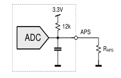
The APS pin provides the possibility to select the address by connecting a resistor to V1 return (0 V). A fixed addressing offset exists between the Controller and the EEPROM.
NOTES:
- If the APS pin is left open, the supply will operate with the Power Management Bus protocol at controller / EEPROM addresses 0xB6 / 0xA6.
- The APS pin is only read at start-up of the power supply. Therefore, it is not possible to change address dynamically.
I2C Address 5
RAPS (Ω) 4
Protocol
Controller
EEPROM
820
0xB0
0xA0
2700
0xB2
0xA2
Power Management Bus 5600
0xB4
0xA4
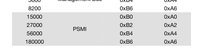
Figure 18. I2C address and protocol setting
8.15 CONTROLER AND EEPROM ACCESS
The controller and the EEPROM in the power supply share the same I2C bus physical layer, see Figure 16. An I2C driver device assures logic level shifting (3.3/5 V) and a glitch-free clock stretching. The driver also pulls the SDA/SCL line to nearly 0 V when driven low by the DSP or the EEPROM providing maximum flexibility when additional external bus repeaters are needed. Such repeaters usually encode the low state with different voltage levels depending on the transmission direction.
The DSP will automatically set the I2C address of the EEPROM with the necessary offset when its own address is changed / set. In order to write to the EEPROM, first the write protection needs to be disabled by sending the appropriate command to the DSP. By default, the write protection is on.
The EEPROM provides 256 bytes of user memory. None of the bytes are used for the operation of the power supply.
4 E12 resistor values, use max 5% resistors 5 The LSB of the address byte is the R/W bit

Page 18
18
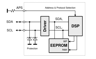
Figure 19. I2C Bus to DPS and EEPROM
8.16 EEPROM PROTOCOL
The EEPROM follows the industry communication protocols used for this type of device. Even though page write / read commands are defined, it is recommended to use the single byte write / read commands.
WRITE
The write command follows the SMBus 1.1 Write Byte protocol. After the device address with the write bit cleared a first byte with the data address to write to is sent followed by the data byte and the STOP condition. A new START condition on the bus should only occur after 5ms of the last STOP condition to allow the EEPROM to write the data into its memory.
S Address W A
Data Address A Data A P
READ
The read command follows the SMBus 1.1 Read Byte protocol. After the device address with the write bit cleared the data address byte is sent followed by a repeated start, the device address and the read bit set. The EEPROM will respond with the data byte at the specified location.
S Address W A
Data Address A
S Address R A
Data nA P
8.17 POWER MANAGEMENT BUS PROTOCOL
The Power Management Bus is an open standard protocol that defines means of communicating with power conversion and other devices. For more information, please see the System Management Interface Forum web site at www.powerSIG.org. Power Management Bus command codes are not register addresses. They describe a specific command to be executed. The PFS1200-12-054NAH supply supports the following basic command structures:
- Clock stretching limited to 1 ms
- SCL low time-out of >25 ms with recovery within 10 ms
- Recognized any time Start/Stop bus conditions
WRITE
The write protocol is the SMBus 1.1 Write Byte/Word protocol. Note that the write protocol may end after the command byte or after the first data byte (Byte command) or then after sending 2 data bytes (Word command).
S Address W A
Command A
Data Low Byte1) A
Data High Byte1) A P
1) Optional
In addition, Block write commands are supported with a total maximum length of 255 bytes. See PFS Programming Manual for further information.

Page 19
19
S Address W A
Command A Byte Count A
Byte 1 A
Byte N A P
READ
The read protocol is the SMBus 1.1 Read Byte/Word protocol. Note that the read protocol may request a single byte or word.
S Address W A
Command A Byte Count A
Byte 1 A
Byte N A P
In addition, Block read commands are supported with a total maximum length of 255 bytes. See PFS Programming Manual BCA.00006 for further information.
S Address W A
Command A S Address R A
Byte Count A
Byte 1 A Byte N nA P
8.18 PSMI PROTOCOL
New power management features in computer systems require the system to communicate with the power supply to access current, voltage, fan speed, and temperature information. Current measurements provide data to the system for determining potential system configuration limitations and provide actual system power consumption for facility planning. Temperature and fan monitoring allow the system to better manage fan speeds and temperatures for optimizing system acoustics. Voltage monitoring allows the system to calculate input wattage and warning of system voltage regulation problems. The Power Supply Management Interface (PSMI) supports diagnostic capabilities and allows managing of redundant power supplies. The
communication method is SMBus. The current design guideline is version 2.12.
The communication protocol is register based and defines a read and write communication protocol to read / write to a single register address. All registers are accessed via the same basic command given below. No PEC (Packet Error Code) is used.
WRITE
The write protocol used is the SMBus 2.0 Write Word protocol. All writes are 16-bit words; byte reads are not supported nor allowed. The shaded areas in the figure indicate bits and bytes written by the PSMI master device. See PFS Programming Manual for further information.
S Address W A Register ID A
A Data High Byte A P Data Low Byte
READ
The read protocol used is the SMBus 2.0 Read Word protocol. All reads are 16-bit words; byte reads are not supported nor allowed. The shaded areas in the figure indicate bits and bytes written by the PSMI master device. See PFS Programming Manual for further information.
S Address W A
Register ID A
S Address R A Data Low Byte
A Data High Byte nA P
8.19 GRAPHICAL USER INTERFACE
Bel Power Solutions provides with its “Bel Power Solutions I2C Utility” a Windows® XP/Vista/Win7 compatible graphical user interface allowing the programming and monitoring of the PFS1200-12-054NAH Front-End. The utility can be downloaded on: belfuse.com/power-solutions and supports Power Management Bus protocols.
The GUI allows automatic discovery of the units connected to the communication bus and will show them in the navigation tree. In the monitoring view the power supply can be controlled and monitored.

Page 20
20
If the GUI is used in conjunction with the SNP-OP-BOARD-01 or YTM.G1Q01.0 Evaluation Kit it is also possible to control the PSON_L pin(s) of the power supply.
Further there is a button to disable the internal fan for approximately 10 seconds. This allows the user to take input power measurements without fan consumptions to check efficiency compliance to the Climate Saver Computing Platinum specification.
The monitoring screen also allows to enable the hot-standby mode on the power supply. The mode status is monitored and by changing the load current it can be monitored when the power supply is being disabled for further energy savings. This obviously requires 2 power supplies being operated as a redundant system (as in the evaluation kit).
NOTE: The user of the GUI needs to ensure that only one of the power supplies have the hot-standby mode enabled.
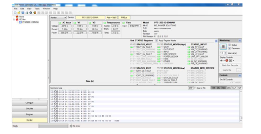
Figure 20. Monitoring dialog of the I2C Utility
To achieve best cooling results sufficient airflow through the supply must be ensured. Do not block or obstruct the airflow at the rear of the supply by placing large objects directly at the output connector. The PFS1200-12-054NAH is provided with normal airflow, which means the air enters through the DC-output of the supply and leaves at the AC-inlet. PFS supplies have been designed for horizontal operation. The fan inside of the supply is controlled by a microprocessor. The RPM of the fan is adjusted to ensure optimal supply cooling and is a function of output power and the inlet temperature. For the normal airflow version additional constraints apply because of the AC-connector. In a normal airflow unit, the hot air is exiting
the power supply unit at the AC-inlet. The IEC connector on the unit is rated 105°C. If 70°C mating connector is used then end user must derated the input power to meet a maximum 70°C temperature at the front. NOTE: It is the responsibility of the user to check the front temperature in such cases. The unit is not limiting its power automatically to meet such a temperature limitation.
Normal Airflow
Reverse Airflow

Normal Airflow
Reverse Airflow
Figure 21. Airflow direction
For additional information use other data files, or ask.
Page 21
21
10.1 IMMUNITY
NOTE: Most of the immunity requirements are derived from EN 55024:1998/A2:2003.
IEC / EN 61000-4-2, ±8 kV, 25+25 discharges per test point
ESD Contact Discharge
A
(metallic case, LEDs, connector body) IEC / EN 61000-4-2, ±15 kV, 25+25 discharges per test point
ESD Air Discharge
A
(non-metallic user accessible surfaces) IEC / EN 61000-4-3, 10 V/m, 1 kHz/80% Amplitude Modulation,
Radiated Electromagnetic Field
A
1 µs Pulse Modulation, 10 kHz…2 GHz IEC / EN 61000-4-4, level 3
Burst
AC port ±2 kV, 1 minute
A
DC port ±1 kV, 1 minute IEC / EN 61000-4-5
Surge
Line to earth: level 3, ±2 kV
A
Line to line: level 2, ±1 kV
RF Conducted Immunity
IEC/EN 61000-4-6, Level 3, 10 Vrms, CW, 0.15 … 80 MHz
A
IEC/EN 61000-4-11 1: Vi 230 V, 100% Load, Phase 0 °, Dip 100%, Duration 10 ms
A
Voltage Dips and Interruptions
2: Vi 230 V, 100% Load, Phase 0 °, Dip 100%, Duration 20 ms
VSB: A, V1: B
3: Vi 230 V, 100% Load, Phase 0 °, Dip 100%, Duration >20 ms
B
10.2 EMISSION
PARAMETER
DESCRIPTION / CONDITION
CRITERION
EN55022 / CISPR 22: 0.15 … 30 MHz, QP and AVG,
Class A
single unit
Conducted Emission
EN55022 / CISPR 22: 0.15 … 30 MHz, QP and AVG,
Class A
2 units in rack system EN55022 / CISPR 22: 30 MHz … 1 GHz, QP,
Class A
single unit
Radiated Emission
EN55022 / CISPR 22: 30 MHz … 1 GHz, QP,
Class A
2 units in rack system IEC61000-3-2, Vin = 115 VAC / 60 Hz, & Vin = 230VAC/ 50 Hz, 100% Load
Harmonic Emissions
Class A
AC Flicker
IEC61000-3-3, Vin = 230 VAC / 60 Hz, 100% Load
Pass
Maximum electric strength testing is performed in the factory according to IEC/EN 62368-1, and UL 62368-1. Input-to-output electric strength tests should not be repeated in the field. Bel Power Solutions will not honor any warranty claims resulting from electric strength field tests.
PARAMETER
DESCRIPTION / CONDITION
MIN
UL 62368-1 CAN/CSA-C22.2 No. 62368-1
Agency Approvals
IEC 62368-1 EN 62368-1 Input (L/N) to case (PE)
Isolation Strength
Input (L/N) to output Output to case (PE) Primary (L/N) to protective earth (PE)
dC Creepage / Clearance
Primary to secondary Input to case
Electrical Strength Test
Input to output Output and Signals to case

NOM MAX
UNIT
Approved
Basic Reinforced Functional
According to
mm
safety standard
According to
kVAC
safety standard
Page 22
22

TAext Extended Temp. Range
Derating output
+40
+65 °C
TS Storage Temperature
Non-operational
-40
+70 °C
Altitude
Operational, above Sea Level, refer derating to Ta
-
3000 m
Na Audible Noise
Vi nom, 50% Io nom, TA = 25°C
60
dBA
PARAMETER
DESCRIPTION / CONDITION
MIN NOM MAX
UNIT
Width
54.5
Dimensions
Height
40.0
mm
Depth
228.6
M Weight
0.87
kg

Page 23
23
Input AC connector Anderson Power Products 2006G1-BK NOTE: A 3D step file of the power supply casing is available on request.
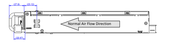
Figure 22. Side View
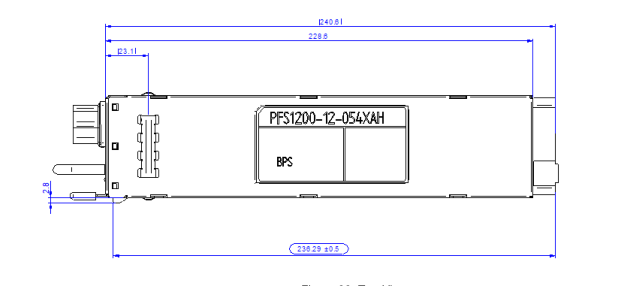
Figure 23. Top View
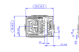
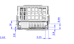
Figure 24. Front and Rear View

Page 24
24
C14 Type Input AC connector Rong Feng SS-120-1.0B-2.8BV or equivalent NOTE: A 3D step file of the power supply casing is available on request.
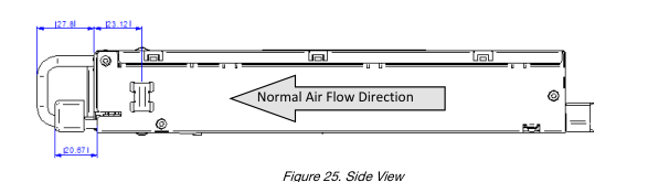
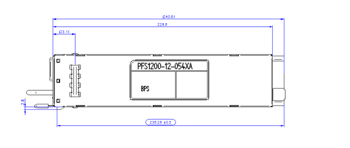
Figure 26. Side View
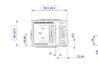
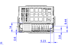
Figure 27. Side View

Page 25
25
C16 Type Input AC connector Rong Feng SS-120B-1.0-4.0Ad or equivalent NOTE: A 3D step file of the power supply casing is available on request.
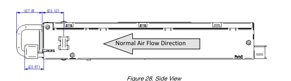
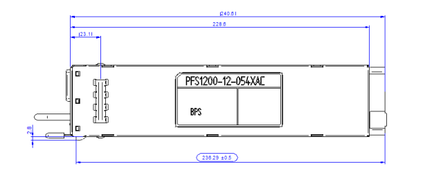
Figure 29. Side View
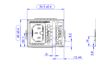
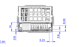
Figure 30. Side View

Page 26
26
AC INPUT CONNECTOR:
PFS1200-12-054NAH: Power supplier connector: ANDERSON POWER PRODUCTS 2006G1-BK Mating connector: Anderson Saf-D-Grid Power cord 2034KZ2 or equivalent, http://www.andersonpower.com/ PFS1200-12-054NA/RA: Power supplier connector: IEC320 C14 type PFS1200-12-054NAC/RAC: Power supplier connector: IEC320 C16 type
DC OUTPUT CONNECTOR:
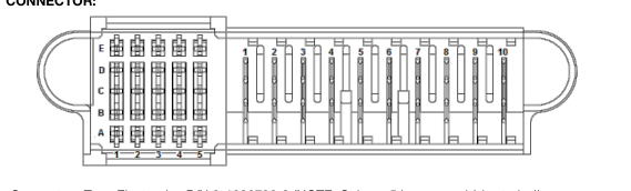
Power Supply Connector: Tyco Electronics P/N 2-1926736-3 (NOTE: Column 5 is recessed (short pins)) Mating Connector: Tyco Electronics P/N 2-1926739-5 or FCI 10108888-R10253SLF
PIN
NAME
DESCRIPTION
Output
+12 VDC main output
6, 7, 8, 9, 10
V1
Power ground (return)
1, 2, 3, 4, 5
PGND
Control Pins
Standby positive output
A1
VSB
Standby positive output
B1
VSB
Standby positive output
C1
VSB
Standby positive output
D1
VSB
Standby positive output
E1
VSB
Signal ground (VSB Return)
A2
SGND
Signal ground (VSB Return)
B2
SGND
Hot standby enable signal: active-high
C2
HOTSTANDBYEN_H
VSB output negative sense
D2
VSB_SENSE_R
VSB output positive sense
E2
VSB_SENSE
I2C address and protocol selection (select by a pull down resistor)
A3
APS
B3
N/C
Reserved I2C data signal line
C3
SDA
Main output negative sense
D3
V1_SENSE_R
Main output positive sense
E3
V1_SENSE
I2C clock signal line
A4
SCL
Power supply on input (connect to A2/B2 to turn unit on): active-low
B4
PSON_L
SMB Alert signal output: active-low
C4
SMB_ALERT_L
VSB voltage selection (See section 8.9)
D4
VSB_SEL1
AC input OK signal: active-high
E4
ACOK_H
Power supply kill (lagging pin): active-high
A5
PSKILL_H
Current share bus (lagging pin)
B5
ISHARE
Power OK signal output (lagging pin): active-high
C5
PWOK_H
VSB voltage selection (See section 8.9)
D5
VSB_SEL2
Power supply present (lagging pin): active-low
E5
PRESENT_L

Page 27
27
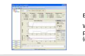
Bel Power Solutions I2C Utility
belfuse.com/power-solutions
Windows XP/Vista/7 compatible GUI to
N/A
program, control and monitor PFS Front-Ends (and other I2C units)


Page 28
28
PREPARED APPROVED
ECO / MCO
DATE
REVISION CHANGE
BY
BY
REF. NO.
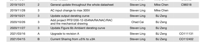
2019/10/21
1 Initial release
Mike Chen
Mike Chen
C92902
NUCLEAR AND MEDICAL APPLICATIONS - Products are not designed or intended for use as critical components in life support systems, equipment used in hazardous environments, or nuclear control systems. TECHNICAL REVISIONS - The appearance of products, including safety agency certifications pictured on labels, may change depending on the date manufactured. Specifications are subject to change without notice.