


 Download PDF
PFDF SCHURTER
Document overview
- PDF pages: 2
Technical content
Page 1
Resettable Fuses
Surface Mount Fuse, PTC, 2018 footprint, 5.1 x 4.6 mm, 60 VDC
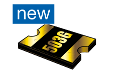
60.0 VDC · 0.55 A
Description
- Directly solderable on printed circuit boards Standards - UL 1434 - CSA C22.2 no. 0, TIL no. CA-3A Approvals - UL File Number: E172175
Technical Data V max
60.0 VDC
Imax
10 A
I hold
0.55 A
Mounting
PCB,SMT
Allowable Operation Temp.
-40 °C to 85 °C
Material: Terminals
Electroless Nickel under Immerion Gold
Weight
0.03 g
Storage Conditions
0 °C to 40 °C, max. 70% r.h.
Product Marking
I hold, Data Code
Dimensions
5.1 mm
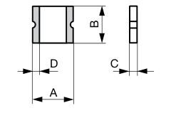
Dimensions A min A max B min
B max C min
C max D min
Order Number
[mm] [mm] [mm] [mm] [mm] [mm] [mm]
4.72 5.44 4.22 4.93 0.79 1.09 0.3 PFDF.050.2
PFDF
www.schurter.com/pg01_1
Applications
- Power Over Ethernet (IEEE 802.3 af) port protection - Automotive electronic control module protection - Telecom equipment low voltage protection References General Product Information Packaging Details Weblinks Approvals, RoHS, CHINA-RoHS, e-Store, Distributor-Stock-Check, Accessories, Product Change Notification (PCN)
Soldering Methods
Reflow
Solderability
245 °C / 3 sec
Resistance to Soldering Heat 260 °C / 10 sec Passing Aging
+85 °C, 1000 Hours -> +/- 5% Typical Resistance Change
Humidity Aging
+85 °C, 85% r.h., 1000 Hours -> +/- 5% Typical Resistance Change
Thermal Shock
+85 °C to -40 °C, 20 Times -> +/- 10% Typical Resistance Change
Vibration
MIL-STD-883C, Method 2007.1, Test Condition A
Resistance to Solvents
MIL-STD-202, Methode 215
1.5 1.5
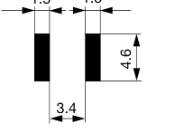
Soldering pads
Fuses
Page 2
PFDF
Resettable Fuses
www.schurter.com/pg01_1
Thermal Derating Chart Ihold [A]
Order Number
-40 °C -20 °C 0 °C 23 °C 40 °C 50 °C 60 °C 70 °C 85 °C Order Number
PFDF.050.2
0.86 0.77 0.7 0.55 0.48 0.43 0.38 0.36 0.26 PFDF.050.2
Electrical Characteristics at 23 °C
Max Time to Tripped Power Order Number
R initial min R 1hour max Max Time to
V max [VDC] I max [A]
I hold [A] I trip [A] [Ω] [Ω] trip [A] Trip [s] Dissipation [W]
60.0 10 0.55 1.2 0.2 1 2.5 3 1.00
PFDF.050.2
Packaging Unit
Blister Tape 36 cm Reel (3000 pcs.)
Time-Current-Curves
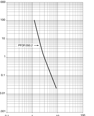
0.1
1
10