

 Download PDF
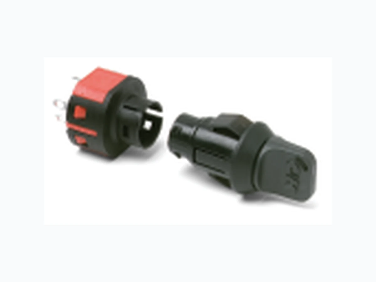
PF011UEBM03KQ22 ITT
Document overview
- PDF pages: 4
Technical content
Page 1
Typical Applications
Features/Benefits
- Snap-in mounting
- Computers
- Multi-pole and multi-position • Point-of-sale terminals
- Positive detent
- Instrumentation
Models Available
Specifications
CONTACT RATING: Q contact material: 4 AMPS @ 125 V AC or 28 V DC; 2 AMPS @ 250 V AC (UL/CSA). See page M-30 for additional ratings. ELECTRICAL LIFE: 10,000 make-and-break cycles at full load. CONTACT RESISTANCE: Below 10 m Ω typ. initial @ 2-4 V DC, 100 mA, for both silver and gold plated contacts. INSULATION RESISTANCE: 109 Ω min. DIELECTRIC STRENGTH: 1,000 Vrms min. @ sea level. INDEXING: 45º: 3 positions, 90º:2 positions.
Build-A-Switch
Materials
LOCK: 6/6 nylon with matte finish (UL 94V-2), black, 5 tumbler, single bitted lock with integral detent mechanism. KEYS: Two nickel plated brass keys with black plastic head. SWITCH HOUSING: 6/6 nylon (UL 94V-2). CONTACTS & TERMINALS: Q contact material: Copper, silver plated. See page M-30 for additional contact materials. TERMINAL SEAL: Epoxy.
NOTE: Any models supplied with Q or B contact material are RoHS compliant. For the latest information regarding RoHS compliance, please go to: www.ittcannon.com/rohs.
NOTE: Specifications and materials listed above are for switchlocks with standard options. For information on specific and custom switchlocks, consult Customer Service Center.
To order, simply select desired option from each category and place in the appropriate box. Available options are shown and described on pages M–28 through M–30. For additional options not shown in catalog, consult Customer Service Center.
Switch and lock Function PF011U SP, 90º Index, keypull pos. 1 & 2 PF201U DP, 45º Index, keypull pos. 1 & 3 PF211U DP, 90º Index, keypull pos. 1 & 2
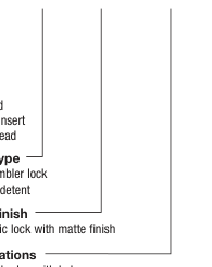
Keying E Two nickel plated brass keys with insert molded plastic head Lock Type B 5 Tumbler lock with detent
Lock Finish
Terminations 03 Solder lug with hole WC Wire lead
M
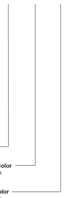
Lock Style K Cone shaped facing
Contact Material Q Silver B Gold
Lock Color 2 Black
Key Color Black
M–27
Page 2
SWITCH AND LOCK FUNCTION
| SINGLE & DOUBLE POLE SWITCHES | |||||||
| NO. POLES | MODEL NO. | CONNECTED TERMINALS | KEY PULL POSITIONS | LOCK CONFIGURATION | INDEXING | ||
| POS. 1 | POS. 2 | POS. 3 | |||||
| DP | PF201U | 8-1, 4-5 | 1-2, 5-6 | 2-3, 6-7 | Positions 1 & 3 | POS. 1 2 3 | 45º |
| SP DP | PF011U PF211U | 8-1 8-1, 4-5 | 1-3 1-3, 5-7 | Positions 1 & 2 | POS. 1 2 | 90º | |
All models
with all options when ordered with ‘Q’ contact material.
LEGEND
= Detent Positions (45º or 90º )
= Key pull possible in these positions.
= Stop Positions
.615
TERMINAL NUMBERS
Terminal numbers molded on housing.
| .615 .700 D (15,62) (17,78 .500 .230 TYP (12,70) (5,84) .420 DIA (10,67ø) 7 8 .625 (15,88) 1 2 .080 x .020 (2,03)x(0,51) | IA. ø) 45º0 6 5 |
|---|---|
| 3 4 |
.625DIA (15,88ø) .163 (4,14)
POS.1
22º30'
POS.2
Part number shown: PF011UEBM03KQ22
M
KEY COLOR
KEYING
KEYING
E TWO NICKEL PLATED BRASS KEYS WITH INSERT MOLDED PLASTIC HEAD
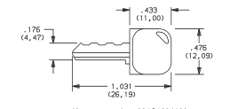
| OPTION CODE | KEY COLOR |
| 2 | BLACK |
Key part number: 334C1004102
NOTE: All orders keyed alike, standard. For more than one key code, replacement keys, or other special features, consult Customer Service Center.
M–28
Page 3
LOCK TYPE
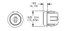
B 5 TUMBLER LOCK WITH DETENT
.615 (15,62)
.163
.500
.230 TYP
(4,14)
(5,84)
(12,70)
.625 (15,88)
LOCK FINISH
M PLASTIC LOCK WITH MATTE FINISH
TERMINATIONS
03 SOLDER LUG WITH HOLE
LOCK STYLE
K CONE SHAPED FACING
LOCK COLOR
LOCK TYPE
OPTION
LOCK COLOR
CODE
2
BLACK
WC WIRE LEAD
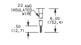
Black wire standard, other colors and lengths available, consult Customer Service Center. UL style 1015.
M
Switch and Lock Assembly Instructions
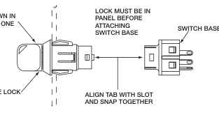
PANEL MOUNTING
KEY SHOWN IN
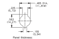
POSITION ONE
5 TUMBLE LOCK
.050-.080 (1,27-2,03)

Page 4
CONTACT MATERIAL
| OPTION CODE | RoHS COMPLIANT* | RoHS COMPATIBLE* | CONTACT AND TERMINAL MATERIAL | RATING | |
|---|---|---|---|---|---|
| Q | YES | YES | SILVER 2 | POWER | 4 AMPS @ 125 V AC or 28 V DC; 2 AMPS @ 250 V AC (UL/CSA). |
| B | YES | YES | GOLD 1 | LOW LEVEL/DRY CIRCUIT | 0.4 VA MAX. @ 20 V AC or DC MAX. |
\* Note: See Technical Data section of this catalog for RoHS compliant and compatible definitions and specifications.
1 CONTACTS & TERMINALS: Copper, with gold plate over nickel plate.
All models
with all options when ordered with ‘Q’ contact material.
2 CONTACTS & TERMINALS: Copper, silver plated (standard with all termination options).
AVAILABLE HARDWARE
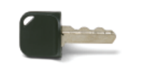
Key Code: 041 PART NO. (ONE KEY)
Material: Brass
334C1004102 BLACK
Finish: Nickel plate 6/6 Nylon insert molded head
M
M–30