
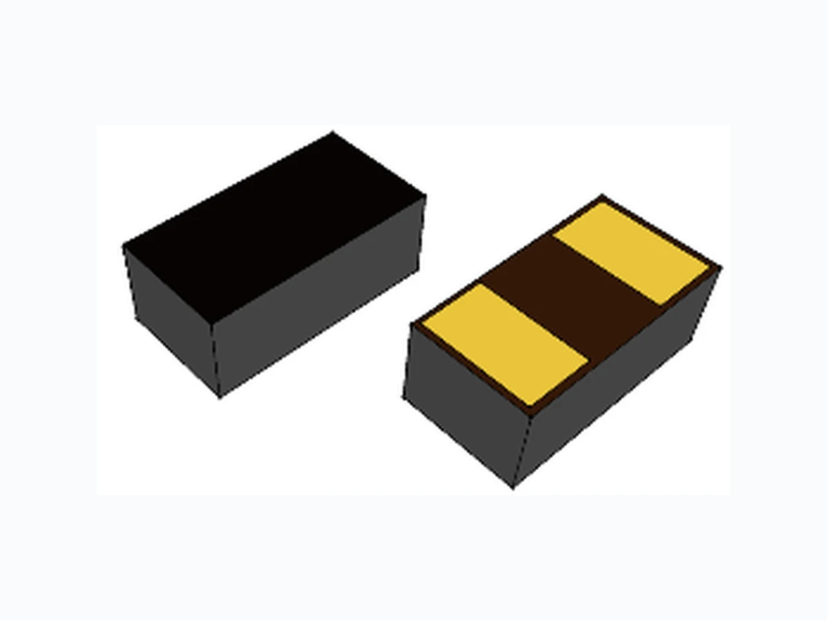
PESD0942U005 LEIDITECH
Document overview
- Manufacturer or author: Provided By www.digicamel.com(FREE DATASHEET DOWNLOAD SITE)
- PDF pages: 3
Technical content
Features
Case: 0402 (plastic package). Lead free; RoHS compliant Molding Compound Flammability Rating: UL 94 V-0 Terminals: High temperature soldering guaranteed: 260 °C/10 sec. at terminals
Electrical Characteristics
A = 25 °C unless otherwise specified)
Applications
USB3.0, Firewire, DVI, HDMI, S-ATA Thunderbolt, Display Port Mobile HDMI Link, MDDI, MIPI, SWP / NFC 2 1 ESD protection for high speed data lines to IEC6100 0 -4-2 ESD contact discharge typical 8KV, max 15KV ESD air discharge typical 15KV, max 25KV Surface mount Extremely low capacitance Very low leakage current Fast response time Bi-directional ESD protection Lead free solder termination The best ESD protection for high frequency, low voltage applications Parameter Unit Maximum Contact discharge voltage Per IEC61000-4-2 --- 15KV V Maximum Air discharge voltage Per IEC61000-4-2 --- 25KV V Maximum Operating temperature T OPER -40 to +90 /degreecentigrade Maximum Storage temperature T STG -55 to +125 /degreecentigrade Maximum lead temperature for soldering during 10s T L 260 /degreecentigrade Parameter Symbol Test Conditions Min Typ Max Units Rated Voltage V R --- 9 V Trigger voltage V T IEC61000-4-2 8KV contact discharge 300 V Clamping voltage V C IEC61000-4-2 8KV contact discharge 35 V Leakage current I L DC 12V shall be applied on component 0.10 uA Capacitance C P V R = 0V, f = 1MHz 0.05 pF Note: 1 Trigger and clamping voltage are measured per IEC 61000-4-2, 8KV contact discharge method. Symbol Value Rev : www.leiditech.com 01.06.2016 1/3
(6'7(67(5 5*8 *+]',*,7$/ 26&,//26&23( ȍ ȍFRD[ î $77(18$725 ȍ '87 '(9,&(81'(57(67 ,(&QHWZRUN ȍ (6'&ODPSLQJ7HVW Typical ESD Response (IEC 61000-4-2, 8KV contact discharge) Time(ns) -50 100 150 200 250 300 350 400 450 0 10 20 30 40 50 60 70 80 90 Voltage ( V ) Typical Device Capacitance VS. Frequency 0.01 0.02 0.03 0.04 0.05 0.06 Capacitance(pF) Frequency(Hz) ESD Protection for Signal Line The CESD is designed for the protection of one bidirectional data line from ESD damage. Place the CESD as close to the input terminal or connector as possible. Minimize the path length between the CESD and the protected signal line. Use ground planes whenever possible. GND Signal line to be protected Rev : www.leiditech.com 01.06.2016 2/3
3URGXFW'LPHQVLRQ L P PLOOPHWHUV PLQ PD[ 5() %6& PESD0942U005 Shanghai Leiditech Electronic Co.,Ltd Email: sale1@leiditech.com Tel : +86- 021 50828806 Fax : +86- 021 50477059 Rev : www.leiditech.com 01.06.2016 3/3