

 Download PDF
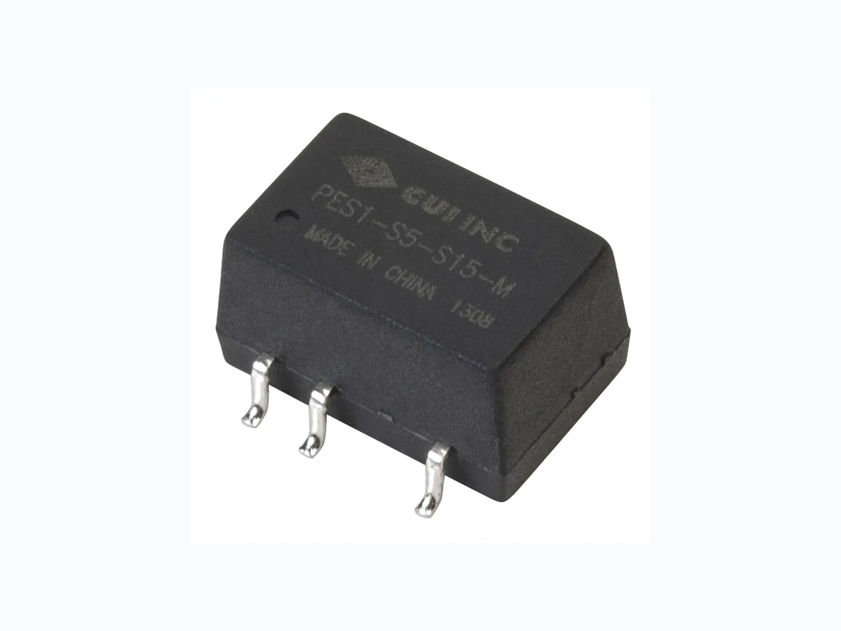
PES1-M CUI
Document overview
- PDF pages: 6
Technical content
Page 1
date date 03/19/2013 page 1 of 6 1 of 6 page
SERIES: PES1-M │ DESCRIPTION: DC-DC CONVERTER
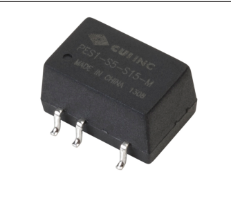
FEATURES
- 1 W isolated output
- smaller package
- single unregulated output
- 3,000 Vdc isolation
- continuous short circuit protection
- extended temperature range (-40~105°C)
- antistatic protection up to 8kV
- high efficiency at light load
- efficiency up to 81%
MODEL
input
output
output
output
ripple
efficiency
voltage
voltage
current
power
and noise1
typ range
min max
max
typ
typ
(Vdc)
(Vdc)
(Vdc)
(mA) (mA)
(W)
(mVp-p)
(%)
PES1-S5-S5-M
5 4.5~5.5
5
20 200
1
30
80
PES1-S5-S9-M
5 4.5~5.5
9
12 111
1
30
80
PES1-S5-S12-M
5 4.5~5.5
12
9 84
1
30
80
PES1-S5-S15-M
5 4.5~5.5
15
7 67
1
60
80
PES1-S5-S24-M
5 4.5~5.5
24
4 42
1
60
80
PES1-S12-S5-M
12 10.8~13.2
5
20 200
1
30
80
PES1-S12-S9-M
12 10.8~13.2
9
12 111
1
30
80
PES1-S12-S12-M
12 10.8~13.2
12
9 84
1
30
81
PES1-S12-S15-M
12 10.8~13.2
15
7 67
1
60
81
PES1-S15-S15-M
15 13.5~16.5
15
7 67
1
60
81
PES1-S24-S5-M
24 21.6~26.4
5
20 200
1
30
80
PES1-S24-S9-M
24 21.6~26.4
9
11 110
1
30
80
PES1-S24-S15-M
24 21.6~26.4
15
7 67
1
60
81
PES1-S24-S24-M
24 21.6~26.4
24
4 42
1
60
81
Notes: 1. ripple and noise are measured at 20 MHz BW by “parallel cable” method
Page 2
date 03/19/2013 │ page 2 of 6
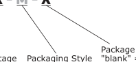
PART NUMBER KEY
PES1 - SXX - SXX - M - X
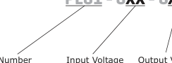
Output Voltage
Base Number
SMT
INPUT
parameter
conditions/description 5 V input models 12 V input models
operating input voltage
15 V input models 24 V input models for maximum of 1 second 5 V input models
surge voltage
12 V input models 15 V input models 24 V input models
filter
capacitance filter
OUTPUT
parameter
conditions/description
line regulation
for Vin change of 1%
load regulation
measured from 10% load to full load
voltage accuracy
see tolerance envelope curve
switching frequency
100% load, nominal input voltage
temperature coefficient
100% load
PROTECTIONS
parameter
conditions/description
short circuit protection
continuous, automatic recovery
SAFETY AND COMPLIANCE
parameter
conditions/description
isolation voltage
for 1 minute at 1 mA max.
isolation resistance
at 500 Vdc
conducted emissions
CISPR22/EN55022, class B, (external circuit required)
radiated emissions
CISPR22/EN55022, class B, (external circuit required)
ESD
IEC/EN61000-4-2, class B, contact ±8kV
MTBF
MIL-HDBK-217F @ 25°C
RoHS compliant
yes
ENVIRONMENTAL
parameter
conditions/description
operating temperature
see derating curve
storage temperature storage humidity
non-condensing
temperature rise
at full load
Package Options "blank" = standard TR = Tape & Reel
min
typ
max
units
4.5
5 5.5
Vdc
10.8
12 13.2
Vdc
13.5
15 16.5
Vdc
21.6
24 26.4
Vdc
-0.7
9 Vdc
-0.7
18
Vdc
-0.7
21
Vdc
-0.7
30
Vdc
min
typ
max
units
±1.2
%
15
%
100
300
kHz
±0.03
%/°C
min
typ
max
units
min
typ
max
units
3,000
Vdc
1,000
MΩ
3,500,000
hours
min
typ
max
units
-40
105
°C
-55
125
°C % °C
Page 3
date 03/19/2013 │ page 3 of 6
SOLDERABILITY
parameter
conditions/description
min
typ
max
units
hand soldering
1.5 mm from case for 10 seconds
300
°C
reflow soldering
see reflow soldering profile
245
°C

parameter
conditions/description
min
typ
max
units
dimensions
12.70 x 8.30 x 7.25 (0.500 x 0.327 x 0.285 inch)
mm
case material
epoxy resin (UL94-V0)
weight
1.52
g
MECHANICAL DRAWING
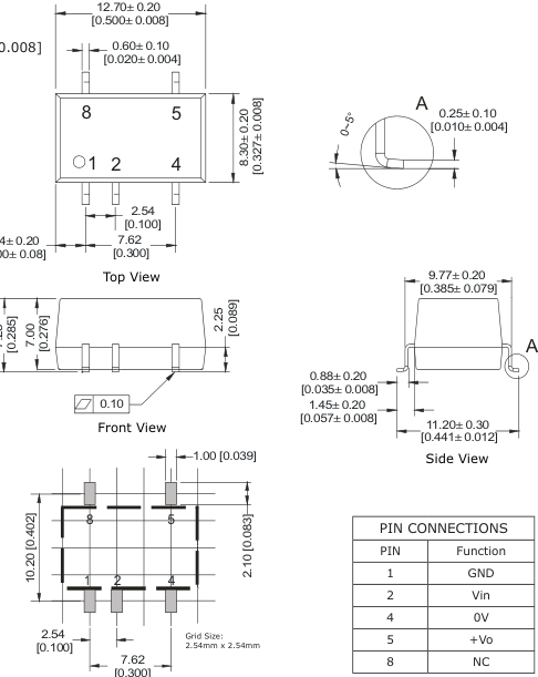
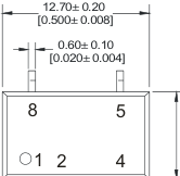
units: mm[inch] tolerance: ±0.20[±0.010] pin section tolerance: ±0.10[±0.008]
2.54 [0.100
PCB Layout Top View
Page 4
DERATING CURVES
Tolerance Envelope Curve
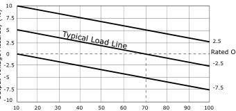
Rated Output Voltage
Output Current Percentage (%) (Nominal Input Voltage)
EMC RECOMMENDED CIRCUIT
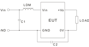
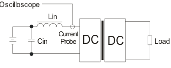
TEST CONFIGURATION
date 03/19/2013 │ page 4 of 6
Temperature Derating Curve
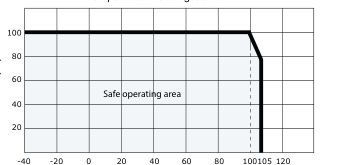
Ambient Temperature (°C)
| Recommended external circuit patterns | |||
| Vin (Vdc) | C1 | LDM | C2 |
| 5 | 4.7μF/50V | 6.8μH | NC |
| 12 | 4.7μF/50V | 6.8μH | NC |
| 15 | 4.7μF/50V | 6.8μH | 470pF/3KV |
| 24 | 4.7μF/50V | 6.8μH | 470pF/3KV |
| External components | |
| Lin | 4.7μH |
| Cin | 220μF, ESR < 1.0Ω at 100 KHz |
Note: Input reflected-ripple current is measured with an inductor Lin and Capacitor Cin to simulate source impedance.
Page 5
date 03/19/2013 │ page 5 of 6
APPLICATION NOTES
- Output load requirement To ensure this module can operate efficiently and reliably, the minimum output load may not be less than 10% of the full load during operation. If the actual output power is low, connect a resistor at the output end in parallel to increase the load.
- Overload Protection Under normal operating conditions, the output circuit of this product has no protection against overload. The simplest method to add this is to add a circuit breaker to the circuit.
- Recommended circuit If you want to further decrease the input/output ripple, you can increase the capacitance accordingly or choose capacitors with low ESR (see Figure 1). However, the capacitance of the output filter capacitor must be appropriate. If the capacitance is too high, a startup problem might arise. For every channel of the output, to ensure safe and reliable operation, the maximum capacitance must be less than the maximum capacitive load (see Table 1).
+Vo
Vin
Figure 1
DC DC
Cout
Cin GND
0V
| Vin (Vdc) | Cin (µF) | Vo (Vdc) | Cout (µF) |
| 5 | 4.7 | 5 | 10 |
| 12 | 2.2 | 9 | 4.7 |
| 15 | 2.2 | 12 | 2.2 |
| 24 | 1 | 15 | 1 |
| -- | -- | 24 | 0.47 |
Table 1
It’s not recommended to connect any external capacitors in applications with less than 0.5 watt output.
- Output Voltage Regulation and Over-voltage Protection Circuit The device for output voltage regulation, over-voltage and over-current protection is a linear regulator and a capacitor filtering net work with overheat protection which can be connected to the input or output end in series (see Figure 2). The recommended capaci tance of its filter capacitor (see Table 1), and the linear regulator is based on the actual voltage and current required.
+Vo REG
Vin REG
Figure 2
DC DC GND
0V
- Operation under minimum load will not damage the converter; however, they may not meet all specifications listed. Note: 2. Max. capacitive load tested at input voltage range and full load. 3. All specifications measured at: Ta=25°C, humidity<75%, nominal input voltage and rated output load, unless otherwise specified.
Page 6
date 03/19/2013 │ page 6 of 6
REVISION HISTORY
| rev. | description | date |
|---|---|---|
| 1.0 | initial release | 03/19/2013 |
The revision history provided is for informational purposes only and is believed to be accurate.
Headquarters 20050 SW 112th Ave.
Fax 503.612.2383
Tualatin, OR 97062 800.275.4899
techsupport@cui.com
CUI offers a two (2) year limited warranty. Complete warranty information is listed on our website.
CUI reserves the right to make changes to the product at any time without notice. Information provided by CUI is believed to be accurate and reliable. However, no responsibility is assumed by CUI for its use, nor for any infringements of patents or other rights of third parties which may result from its use.
CUI products are not authorized or warranted for use as critical components in equipment that requires an extremely high level of reliability. A critical component is any component of a life support device or system whose failure to perform can be reasonably expected to cause the failure of the life support device or system, or to affect its safety or effectiveness.