
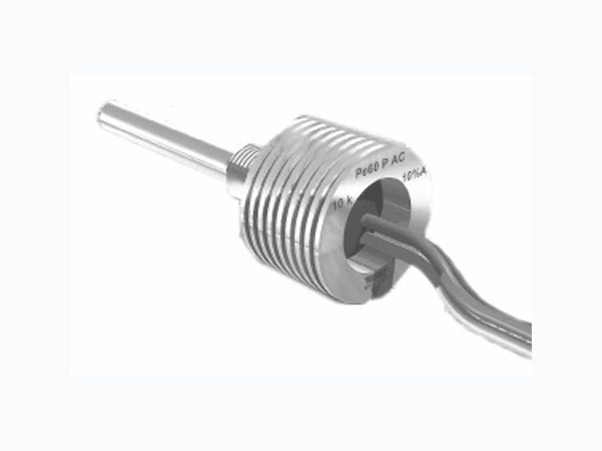
PE60 VISHAY
Document overview
- Manufacturer or author: Provided By www.digicamel.com(FREE DATASHEET DOWNLOAD SITE)
- PDF pages: 5
Technical content
www.vishay.com For technical ques tions, contact: sfer@vishay.com Document Number: 51005
134 See also: Application notes
Revision: 05-Jun-08 PE60 Vishay Sfernice Power Panel Potentiometer
FEATURES
- High power rating (6 W at 50 °C)
- Cermet element
- Full sealing
- Mechanical strength
- Industrial and professional grade
- Tests according to CECC 41 000 DIMENSIONS in millimeters Ø 25 8 150 (5.872) Min (0.709) FR = 50 (1.969) FL = 25 (0.984)FG = 16 (0.630) (0.472) wrench = 14 (0.551) Thread M 10 x 75 Slot 1 x 1.8 deep (0.039 x 0.071) Ø 6 (0.236) wrench = 14 (0.551) wrench = 12 (0.472) 6.5 (0.256) Ø 6 (0.236) (0.591) Available only with PE 60 L 0.8 (0.031) 2.3 (0.091) 3 (0.118) Ø 1.8 (0.071) 9.2 (0.362) 12.5 (0.492) 3 (0.118) Available on PE 60 L and PE 60 F Ø 1.2 (0.047) Ø 10.5 (0.413) Available only with bushing M10 x 0.75 and shafts Ø 6 mm Flat Located0.7 (0.028) Sealing ring FD = 13 (0.514) FJ = 22 (0.868) FP = 47 (1.852) 8 ± 0.2 (0.315 ± 0.008) Ø 6 (0.236) (1) (2) CW (3) GreenYellow Red 150 (5.872) Min (0.709) GR = 50.8 (2) GJ = 22.22 (7/8)GB = 12.7 (1/2) 9.52 (3/8) wrench = 12.5 (0.492) Thread 3/8 32-UNEF-2A Slot 1 x 1.8 deep (0.039 x 0.071) Ø 6.35 (0.250) CIRCUIT DIAGRAMPanel sealed version PE 60 M OPTION E: Including locating peg (available only for PE 60 M) OPTION D: DBAN SHAFT LOCKING OPTION L: PE 60 LPRP - WITH LOCATING PEG PE 60 L PE 60 F RoHS COMPLIANT
Power Panel Potentiometer Vishay Sfernice Document Number: 51005 For technica l questions, contact: sfer@vishay.com See also: Application notes www.vishay.com Revision: 05-Jun-08 135 SPECIAL FEATURES COMMAND SHAFT Length is measured from the mounting surface to the free end of the shaft. The screwdriver slot is aligned with the wiper within ± 10°. Special shafts are available, in accordance to drawings supplied by customers. We recommend that customers sh ould not machine shafts, in order to avoid damage. PANEL SEALING: PE60M The panel sealing device consists of a ring located in a slot on the potentiometer face. Sealing is obtained by tightening the ring against the panel when mounting the potentiometer. SHAFT LOCKING: DBAN The shaft locking device consists of a tapered nut tightening a slotted notched washer against both bushing and shaft. DBAN tightening torque is 200 Ncm, shaft locking torque being 30 Ncm. DBAN is also available with all special types. This device is normally supplied in a separate bag. Can be pre-mounted on request. LOCATING PEG: LPRP Location is obtained by fitting a special washer on the potentiometer face. The peg can therefore be positioned at MECHANICAL SPECIFICATIONS Mechanical Travel 300° ± 5° Operating Torque (max. Ncm) 3 typical End Stop Torque (max. Ncm) 70 Max Tightening Torque of Mounting Nut (Ncm) 250 Unit Weight (max. g) 25 to 35 POWER RATING CHART ENVIRONMENTAL SPECIFICATIONS Temperature Range - 55 °C to + 125 °C Climatic Category 55/125/56 Sealing fully sealed container IP67 RESISTANCE LAWS ELECTRICAL SPECIFICATIONS Resistive Element cermet Electrical Travel 270° ± 10° Resistance Range Linear Law 1 Ω to 1 MΩ Logarithmic Laws 100 Ω to 2.2 MΩ Standard series E3 1 - 2 - 2.5 - 5 Tolerance Standard ± 20 % On Request ± 10 % - ± 5 % Power Rating Linear 6 W at + 50 °C Logarithmic 3 W at + 50 °C Temperature Coefficient see Standard Resistance Element Data Limiting Element Voltage (Linear Law) 350 V Contact Resistance Variation (Linear Law) 3 % Rn or 0.5 Ω End Resistance (Typical) 0.5 Ω or 1 % Dielectric Strength (RMS) 2500 V Insulation Resistance (500 VDC) 106 MΩ 0 40 140 125 AMBIENT TEMPERAT U RE IN ° C POWER IN W 70 60 20 100 80 LIN. LAW “A” LOG. LAWS “L & F” 100 0 100 80 60 40 20 % CLOCKWISE SHAFT ROTATION % TO TA L RESIST ANCE F L A
Vishay Sfernice Power Panel Potentiometer www.vishay.com For technical ques tions, contact: sfer@vishay.com See also: Application notes Document Number: 51005 MARKING Printed: - VISHAY trademark - SAP Part number - manufacturing date PACKAGING - in box of 5 pieces PERFORMANCE TESTS CONDITIONS TYPICAL VALUES AND DRIFTS ΔRT RT (%) ΔR1-2 R1-2 (%) Climatic Sequence Phase A dry heat 125 °C Phase B damp heat Phase C cold - 55 °C Phase D damp heat 5 cycles ± 0.5 % ± 1 % Long Term Damp Heat 56 days ± 0.5 % ± 1 % Insulation resistance: > 104 MΩ Rotational Life 25 000 cycles ± 3 % Contact res. variation: < 5 % Rn Load Life 1000 hours at rated power 90’/30’ - ambient temp. 25 °C ± 3 % Contact res. variation: < 3 % Rn Rapid Temperature Change 5 cycles Shock 50 g at 11 ms 3 successive shocks in 3 directions ± 0.1 % ± 0.2 % Vibration 10 - 55 Hz 0.75 mm or 10 g during 6 hours ± 0.1 % ± 0.2 % STANDARD RESISTANCE ELEMENT DATA STANDARD RESISTANCE VALUES LINEAR LAW TYPICAL TCR - 55 °C + 125 °C MAX. POWER AT 25 °C MAX. WORKING VOLTAGE MAX. CUR. THROUGH WIPER Ω WV m A p p m / ° C 1 6 2.4 2449 ± 500 2 3.5 1732 5 5.5 1095 10 7.7 775 20 11.0 548 25 12.2 490 50 17.3 346 ± 250 100 24.5 245 200 34.6 173.2 250 38.7 154.9 500 54.8 109.5 1K 77.5 77.5 2K 110 54.8 2.5K 122 49.0 5K 173 34.64 10K 245 24.49 20K 6 346 17.32 25K 4.90 350 14.00 50K 2.45 7.00 100K 1.23 3.50 200K 0.61 1.75 250K 0.49 1.40 500K 0.25 0.70 1M 0.12 350 0.35
Power Panel Potentiometer Vishay Sfernice Document Number: 51005 For technica l questions, contact: sfer@vishay.com See also: Application notes www.vishay.com Revision: 05-Jun-08 137 SAP ORDERING INFORMATION (Part Number 18 digits) MODEL BUSHING OPTION SHAFT LEADS OHMIC VALUE TOLERANCE LAW SPECIAL NUMBER M = Panel sealed L = STD F = 3/8" 0 = none For L Bushing D = DBAN L = LPRP B = DBAN and LPRP For F Bushing L = LPRP For M Bushing E = Peg For L Bushing FG 16 mm, slotted FL 25 mm, slotted FR 50 mm, plain For F Bushing GB 1/2", slotted GJ 7/8", slotted GR 2", slotted For M Bushing FD = 13 mm, slotted FJ = 22 mm, slotted FP = 47 mm, plain W: Wire 204 = 200 kΩ ± 20 % on request ± 10 % ± 5 % A = Linear L = clockwise logarithmic F = clockwise inverse logarithmic (if applicable) Given by VISHAY for custom design PART NUMBER DESCRIPTION (for information only) PE60 L 0 FG W 200 k Ω 20 % AB O 5 e 4 MODEL BUSHING OPTION SHAFT LEADS OHMIC VALUE TOL LAW PACKAGING SPECIAL SPECIAL LEAD (Pb)-FREE L0FG W 20 M P E
Document Number: 91000 www.vishay.com Revision: 18-Jul-08 1 Disclaimer Legal Disclaimer Notice Vishay All product specifications and data are subject to change without notice. Vishay Intertechnology, Inc., its affiliates, agents, and employees, and all persons acting on its or their behalf (collectively, “Vishay”), disclaim any and all liability for any errors, inaccuracies or incompleteness contained herein or in any other disclosure relating to any product. Vishay disclaims any and all li ability arising out of the use or application of any product described herein or of any information provided herein to the maximum extent permit ted by law. The product specifications do not expand or otherwise modify Vishay’s terms and conditions of purcha se, including but not limited to the warranty expressed therein, which apply to these products. No license, express or implied, by estoppel or otherwise, to any intellectual property rights is granted by this document or by any conduct of Vishay. The products shown herein are not designed for use in medi cal, life-saving, or life-sustaining applications unless otherwise expressly indicated. Customers using or selling Vishay products not expressly indicated for use in such applications do so entirely at their own risk and agree to fully indemnify Vishay for any damages arising or resulting from such use or sale. Please contact authorized Vishay personnel to obtain written terms and conditions regarding products designed for such applications. Product names and markings noted herein may be trademarks of their respective owners.