
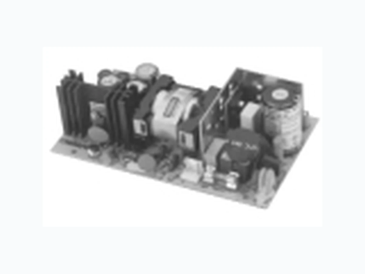
PD65-10 ETC
Document overview
- Manufacturer or author: Provided By www.digicamel.com(FREE DATASHEET DOWNLOAD SITE)
- PDF pages: 2
Technical content
65 Watts
100% Burn-In Small Size, Light Weight Three Wide Input Voltage Ranges 10-30 VDC, 20-60 VDC, 30-90 VDC Overvoltage Protection Overcurrent Protection Specification All specifications typical at nominal line, full load and 25°C PH: 508 429.9883 FAX: 800 226.2100 Email: sales@xp-iq.com Holliston, MA 01746 USAwww.XP-iQ.com Intelligent Design Quality Product XPiQ inc. DC/DC Converters Input Input Voltage • 10 to 30 VDC (PD65 “L” series) 20 to 60 VDC (PD65 “M” series) 30 to 90 VDC (PD65 “H” series) Input Current • 4.1A (rms) for 24 VDC 2.1A (rms) for 48 VDC 1.5A (rms) for 72 VDC Output Output Voltage/ • See rating chart Current Ripple • 1% peak to peak maximum Overvoltage • Provided on output #1 only, Protection set at 112-132% of its nominal output voltage Overcurrent • All outputs protected in short Protection: circuit conditions Temperature • All outputs ±0.04%/°C maximum Coefficient: General Efficiency • 65% - 80% Hold-up time • 10 msec Line Regulation • ±0.5% max. Isolation Voltage • 1000 VDC from input to output Environmental Operating • 0°C to +70°C* Temperature Storage • -40°C to +85°C Temperature MTBF • 100,000 hours Weight • 380 grams - PCB 640 grams - enclosed * Derate linearly from 100% load at 50°C to 50% load at 70°C PD 65 26/4/02 3:10 pm Page 1
PD65-10 PD65-12 OUTPUT OUTPUT OUTPUT OUTPUT RETURN RETURN RETURN RETURN PD65-13 PD65-14 #1 #1 #1 #1 PD65-25 OUTPUT OUTPUT COMMON COMMON OUTPUT OUTPUT N.C. N.C. #1 #1 RETURN RETURN #2 #2 PD65-30 PD65-31 OUTPUT OUTPUT COMMON COMMON OUTPUT OUTPUT OUTPUT N.C. PD65-32 #1 #1 RETURN RETURN #2 #2 #3 PD65-40 OUTPUT OUTPUT COMMON COMMON OUTPUT OUTPUT OUTPUT OUTPUT #1 #1 RETURN RETURN #2 #2 #3 #4 Output #1 Output #2 Output #3 Output #4 Maximum Output Model Vnom Imin Imax Tol. Vnom Imin Imax Tol. Vnom Imin Imax Tol. Vnom Imin Imax Tol. Power 2 PD65-10 5V 0.0A 10A 1% 65W PD65-12 12V 0.0A 5.5A 1% 65W PD65-13 15V 0.0A 4.5A 1% 65W PD65-14 24V 0.0A 3.0A 1% 65W PD65-25 +5V 1.0A 6.0A 3% +24V 0.3A 2.0A 5% 65W PH: 508 429.9883 FAX: 800 226.2100 Email: sales@xp-iq.com Holliston, MA 01746 USAwww.XP-iQ.com Notes Mechanical Details Pin Chart 1. All multi-output units may be operated at no load without damage. At no load, output tolerance increases to 10%. 2. Maximum output power for 10-30 VDC input range is 70% of that shown above. 3. Suffix codes for mechanical format and input range as follows: Input voltage range L: 10-30 VDC
2 Mechanical format: A: PCB only
M: 20-60 VDC C: Enclosed H: 30-90 VDC Example: PD65-31MC (20-60 VDC input range/Enclosed). Dimensions shown in inches (mm)/Tolerence ± 0.02 (0.5) maximum Input connector mates with Molex housing 09-50-3041 and Molex 2878 series crimp terminal Output connector mates with Molex housing 09-50-3081 and Molex 2878 series crimp terminal OPEN PCB “A” ENCLOSED “C” OUTPUT VOLTAGE & CURRENT RATINGS PD 65 PD 65 26/4/02 3:10 pm Page 2