
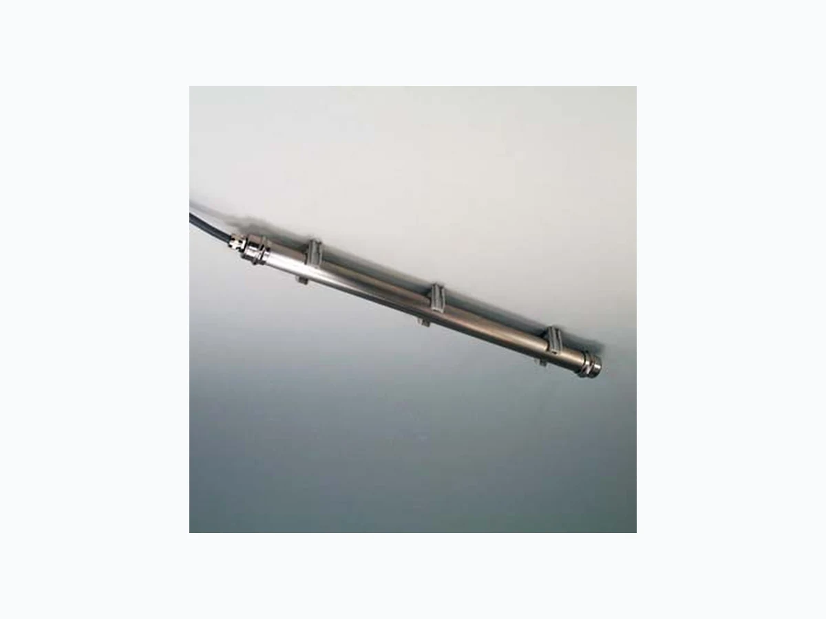
PCRP31 ASM-SENSOR
Document overview
- Manufacturer or author: Provided By www.digicamel.com(FREE DATASHEET DOWNLOAD SITE)
- PDF pages: 7
Technical content
42 CAT-PC-E-04 ASM GmbH
Tel.: +49-8123-986-0 Fax: +49-8123-986-500 www.asm-sensor.com PCRP31 POSICHRON ® Position Sensor Rod Profile with Analog Output POSICHRON® position sensor in a stainless steel pressure case /c183Protection class IP68 /c183Compression-proof up to 15 bar /c183Absolute position measurement /c183No power for the position magnet /c183Wear- and maintenance-free /c183Cable output /c1830 … 10 V output /c1834 … 20 mA output PCRP31-BFS... Order Example: PCRP31 - 2000 - 10V - KAB3M PCMAG... Specifications Outputs Voltage: 0 ... 10 V, 3 wire Current: 4 ... 20 mA, 3 wire Resolution Essentially infinite Sampling rate 0.5 ... 2 kHz depending on measurement range Linearity ±0.1 mm for ranges /c163500 mm ±0.02 % f.s. for ranges >500 mm Housing material Stainless steel 1.4401 Protection class IP68, compression-proof up to 15 bar Operating temperature -40 ... +85 °C EMC, immunity to interference EN61326: 1998, Table A1 EMC, radio frequency emission EN55011 group 1 class A Shock 100 g/s ms according to EN60068-2-27 Vibration 15 g, 10 … 2000 Hz according to EN60068-2-6 Connection Cable output, standard length 3 m Order Code PCRP31 Model Name Measurement Range (in mm) 100 / 500 / 1000 / 1500 / 2000 / 2500 / 3000 / 4000 / 5000 / 5750 Other ranges on request Outputs 10V = with 0 ... 10 V signal conditioner (3 wire) 420T = with 4 ... 20 mA signal conditioner (3 wire) Connection KAB3M = Cable output, lengt h 3 m (standard) PCRP31 Order Code Mounting Set (see accessories page 62) Order Code Position Magnet (see accessories page 58)
Tel.: +49-8123-986-0 Fax: +49-8123-986-500 www.asm-sensor.com POSICHRON® position sensor in a stainless steel pressure case /c183Protection class IP68 /c183Compression-proof up to 15 bar /c183Absolute position measurement /c183No power for the position magnet /c183Wear- and maintenance-free /c183Cable output /c183Pulse output (start/stop) Order Example: PCRP31 - 1500 - STSP - KAB3M PCRP31-BFS... PCMAG... PCRP31 POSICHRON ® Position Sensor Rod Profile with Pulse Output Specifications Output Pulse output (start/stop) Resolution Essentially infinite Sampling rate 0.5 ... 2 kHz depending on measurement range Linearity ±0.1 mm for ranges /c163500 mm ±0.02 % f.s. for ranges >500 mm Housing material Stainless steel 1.4401 Protection class IP68, compression-proof up to 15 bar Operating temperature -40 ... +85 °C EMC, immunity to interference EN61326: 1998, Table A1 EMC, radio frequency emission EN55011 group 1 class A Shock 100 g/s ms according to EN60068-2-27 Vibration 15 g, 10 … 2000 Hz according to EN60068-2-6 Connection Cable output, standard length 3 m Order Code PCRP31 Model Name Measurement Range (in mm) 100 / 500 / 1000 / 1500 / 2000 / 2500 / 3000 / 4000 / 5000 / 5750 Other ranges on request Output STSP = with pulse output (start/stop) Connection KAB3M = Cable output, lengt h 3 m (standard) PCRP31 Order Code Mounting Set (see accessories page 62) Order Code Position Magnet (see accessories page 58)
POSICHRON® position sensor in a stainless steel pressure case /c183Protection class IP68 /c183Compression-proof up to 15 bar /c183Absolute position measurement /c183No power for the position magnet /c183Wear- and maintenance-free /c183Cable output /c183Synchronous serial output (SSI)
44 CAT-PC-E-04 ASM GmbH
Tel.: +49-8123-986-0 Fax: +49-8123-986-500 www.asm-sensor.com Order Example: PCRP31 - 1500 - SSI - KAB3M PCRP31-BFS... PCMAG... PCRP31 POSICHRON ® Position Sensor Rod Profile with SSI Output Specifications Output Synchronous serial (SSI) Resolution Typ. 2 µm Sampling rate 0.5 ... 2 kHz depending on measurement range Linearity ±0.1 mm for ranges /c163500 mm ±0.02 % f.s. for ranges >500 mm Housing material Stainless steel 1.4401 Protection class IP68, compression-proof up to 15 bar Operating temperature -40 ... +85 °C EMC, immunity to interference EN61326: 1998, Table A1 EMC, radio frequency emission EN55011 group 1 class A Shock 100 g/6 ms according to EN60068-2-27 Vibration 15 g, 10 … 2000 Hz according to EN60068-2-6 Connection Cable output, standard length 3 m Order Code PCFP23 Model Name Measurement Range (in mm) 100 / 500 / 1000 / 1500 / 2000 / 2500 / 3000 / 4000 / 5000 / 5750 Other ranges on request Output SSI = with synchronous serial output (SSI) Connection KAB3M = Cable output, lengt h 3 m (standard) PCFP23 Order Code Mounting Set (see accessories page 62) Order Code Position Magnet (see accessories page 58)
Tel.: +49-8123-986-0 Fax: +49-8123-986-500 www.asm-sensor.com Outline drawing (2 + n) x mounting set PCRP31-BFS2 distance approx. 300 … 500 mm Mounting set PCRP31-BFS2 Foot zoneHead zone PCMAG Guiding tolerance: dy = ±12 View AA Overall length A = MR+155 (e.g. 1155) Effective measurement range MR (e.g. 1000) End position PCMAG Start position PCMAG Gap Dimensions informative only For guaranteed dimensions consult factory! PCRP31 POSICHRON ® Position Sensor Rod profile with pressure case
54 CAT-PC-E-04 ASM GmbH
Tel.: +49-8123-986-0 Fax: +49-8123-986-500 www.asm-sensor.com POSICHRON® Output Specification 420T and 10V 420T Excitation + Signal + Excitation GND Excitation + Signal GND Signal +10V Signal GND Signal Wiring Output signals 420T 10V Connector pin no. Cable colour Excitation + Excitation + 1 white Excitation GND Excitation GND 2 brown Signal + Signal + 3 green Signal GND 4 yellow View to sensor connector Connection Mating Connector Signal conditioner 10V Voltage output (3 wire) Excitation voltage +18 ... +27 V DC, residual ripple 10 mV ss Excitation current 80 mA max. Output voltage 0 ... +10 V DC equivalent t o 0 … 100% range Output current 2 mA max. Output load >5k /c87 Stability (temperature) ±50 x 10 -6 / °C full scale Protection Reverse polarity, permanent short circuit Output noise 0,5 mV RMS Operating temperature -40 ... +85 °C Immunity to interference (EMC) According to EN 61326: 1998 Signal Conditioner 420T Current output (3 wire) Excitation voltage +18...+27 V DC, residual ripple 10 mV ss Excitation current 80 mA max. Load resistor 350 /c87max. Stability (temperature) ±50 x 10 -6 / °C full scale Protection Reverse polarity, permanent short circuit Output noise 0.5 mV RMS Operating temperature -40 ... +85 °C Immunity to interference (EMC) According to EN 61326: 1998
56 CAT-PC-E-04 ASM GmbH
Tel.: +49-8123-986-0 Fax: +49-8123-986-500 www.asm-sensor.com POSICHRON® Output Specification Pulse Interface Pulse interface STSP (start/stop) Excitation voltage +18 ... +27 V DC, residual ripple 10 mV ss Excitation current 150 mA max. Stability (temperature) ±50 x 10 -6 / °C full scale Wave velocity 2850 ...2950 m/s Level INIT and START/STOP RS 485 / RS 422 Protection Reverse polarity, short circuit Operating temperature -40 ... +85 °C EMC, interference resistance EN61326: 1998, Table A1 EMC, emitted interference EN55011 Group 1 Class A Signal Diagram Sensor circuit Subsequent circuit The subsequent circuit generates a signal on the INIT line. The position sensor answers with a START and a STOP signal. Position value x = t (x) /c183vs The position value will be calculated by multi- plication of the time interval t(x) with the conversion factor specified on the type label. Signal wiring / connection Pulse interface Connector pin no. Cable colour Excitation + 1 white Excitation GND 2 brown INIT + 3 green INIT – 4 yellow STSP + 5 grey STSP – 6 pink Shield Contact via connector housing black View to sensor connector Mating connector Cable WS-CONN-D8 CONN-M12-8P-X
Tel.: +49-8123-986-0 Fax: +49-8123-986-500 www.asm-sensor.com POSICHRON® Output Specification SSI SSI (synchronous serial ) Output EIA RS-422, RS-485, short-circuit proof Excitation Voltage +12 … +27 V DC, residual ripple 10 mV ss Excitation Current 150 mA max. without load Clock Frequency 100 kHz ... 1 MHz Code Gray 24 bit, continuous progression Resolution 2 µm max. Delay between Pulse Trains >25 µs Stability (Temperature) ±20 x 10 -6 / °C full scale Operation Temperature -40 ... +85 °C Immunity to Interference (EMC) According to EN50082-2, EN50081-1 Data Format (Train of 26 pulses) The data transmission takes place by means of the two signals CLOCK and DATA. The processing unit (PLC, Microcomputer) sends pulse sequences which clocks the data transmission at the required transfer rate. With the first falling edge of the pulse sequence the position of the sensor is recorded and stored. The following rising edges control the bit-by-bit transmission of the data word. After a delay time the next new position information will be transmitted.
Description
Signal diagram Sensor circuit Cable Subsequent circuit DATA DATA CLOCK CLOCK Note: Extension of the cable length will reduce the maximum transmission rate. The signals CLOCK/CLOCK and DATA/DATA must be connected in a twisted pair cable, shielded per pair and common. Cable length Baud rate 50 m 100 … 1000 kHz 100 m 100 … 300 kHzSignal Wiring / Connection Signal name Connector pin no. Cable colour Excitation + 1 white Excitation GND (0V) 2 brown CLOCK 3 green CLOCK 4 yellow DATA 5 grey DATA 6 pink View to sensor connector WS-CONN-D8 CONN-M12-8P-X