
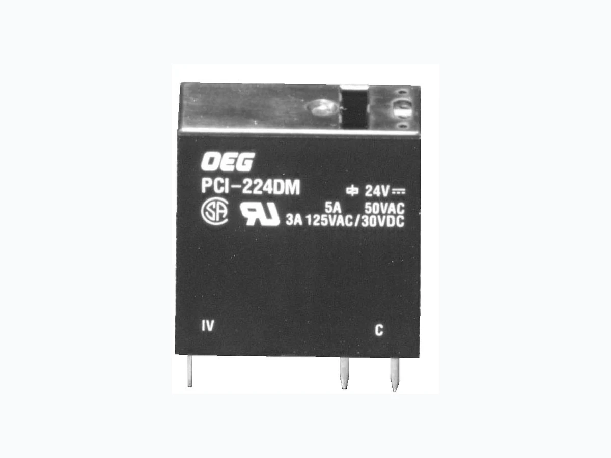
PCI MACOM
Document overview
- Manufacturer or author: Provided By www.digicamel.com(FREE DATASHEET DOWNLOAD SITE)
- PDF pages: 2
Technical content
reference purposes only. Dimensions are in inches over (millimeters) unless otherwise specified. Specifications and availability subject to change. OEG Catalog 1308242 Issued 3-03 www.tycoelectronics.com Technical support: Refer to inside back cover. Rated Coil Nominal Coil Must Operate Must Release Voltage Current Resistance Voltage Voltage (VDC) (mA) (ohms) ± 10% (VDC) (VDC) 5 69.4 72 3.50 0.50 6 58.8 102 4.20 0.60 9 39.1 230 6.30 0.90 12 29.1 413 8.40 1.20 24 14.5 1,650 16.80 2.40 PCI Users should thoroughly review the technical data before selecting a product part number. It is recommended that user also seek out the pertinent approvals files of the agencies/laboratories and review them to ensure the product meets the requirements for a given application.Features
- Slim and simple architecture.
- 2 Form A (DPST-NO) contact arrangement.
- Cadmium-free contacts.
- UL, CSA, approvals.
- Immersion cleanable, sealed version available.
- Magnetic blow-out available for DC loads. Contact Data @ 20 °C Arrangements: 2 Form A (DPST-NO). Material: Ag-GS Alloy. Max. Switching Rate: 300ops./ min. (no load). 30ops./ min. (rated load). Expected Mechanical Life: 1 million ops (no load). Expected Electrical Life: 100,000 ops (rated load). Minimum Load: 1mA @ 1VDC. Initial Contact Resistance: 50 milliohms @ 1mA, 6VDC. Contact Ratings Ratings: 3A @ 24VDC resistive. 3A @ 120VAC resistive. Max. Switched Voltage: AC: 240V. DC: 50V. Max. Switched Current: 5A. Max. Switched Power: 300VA, 90W. Initial Dielectric Strength Between Open Contacts: 1,000VAC, 50/60 Hz. (1 min.). Between Adjacent Contacts: 2,000VAC, 50/60 Hz (1 min). Between Contacts and Coil: 4,000VAC, 50/60 Hz. (1 min.). Surge Voltage Between Coil and Contacts: 7,000V (1.2/50µs). Initial Insulation Resistance Between Mutually Insulated Conductors: 1,000Mohm @ 500VDCM. Coil Data Voltage: 5 to 48VDC. Duty Cycle: Continuous. Nominal Power: 350mW. Max. Coil Power: 130% of nominal at 20°C. PCI series Slim 2 Form A Miniature PC Board Relay Appliances, Audio Equipment, Office Machines UL File No. E82292 CSA File No. LR48471 Coil Data @ 20°C Operate Data @ 20°C Must Operate Voltage: 70% of nominal voltage or less. Must Release Voltage: 10% of nominal voltage or more. Operate Time : 15ms max. Release Time : 5ms max. Environmental Data Temperature Range: Operating: -30°C to +70°C. Vibration, Mechanical: 10 to 55Hz., 1.5mm double amplitude. Operational: 10 to 55Hz., 1.5mm double amplitude. Shock, Mechanical: 1,000m/s2 (100G approximately). Operational: 100m/s2 (10G approximately). Operating Humidity: 20 to 85% RH. (Non-condensing). Mechanical Data Termination: Printed circuit terminals. Enclosure: Plastic sealed case with enclosure option "H". Otherwise, vented (flux-tight) cover. Weight: 0.41 oz (10.5g) approximately.
reference purposes only. Dimensions are in inches over (millimeters) unless otherwise specified. Specifications and availability subject to change. www.tycoelectronics.com Technical support: Refer to inside back cover. OEG Catalog 1308242 Issued 3-03 .984 ± .02 (25.0 ± .5) .945 ± .008 (24.0 ± .2) .018 c (.45) .197 ± .008 (5.0 ± .2) .016 (.4) .59 ± .008 (15.0 ± .2) .295 ± .012 (7.5 ± .3) .157 ± .008 (4.0 ± .2) .394 ± .008 (10.0 ± .2) .094 (2.4) .039 (1.0) .039 (1.0) .016 (.4) .016 (.4) Wiring Diagram (Bottom View) PC Board Layout (Bottom View) Typical Part Number B PCI -2 05 D M ,000 1. Basic Series: PCI = Miniature relay 2. Termination: 2 = 2 pole 3. Coil Voltage: 05 = 5VDC 09 = 9VDC 24 = 24VDC 06 = 6VDC 12 = 12VDC 48 = 48VDC 4. Coil Input: D = Standard 5. Contact Arrangement: M = 2 Form A 6. Enclosure: Blank = Vented (Flux-tight) cover H = Sealed plastic case 7. Optional: Blank = Standard M = with magnetic blow-out 8. Suffix: ,000 = Standard model Other Suffix = Custom model DC Cut Ability for Audio Speaker Loads 2 – .039 DIA (1.0) .197 ± .004 (5.0 ± .1) .59 ± .004 (15.0 ± .1) .295 ± .004 (7.5 ± .1) 4 – .051 DIA (1.3) Note: This data is based on the max. allowable temperature for E type insulation coil (115°C). Coil Power (W) T emp. Rise (°C) -40 -20 Ambient T emp. (°C) % of Supplying Voltage to Coil 0 20 40 60 80 100 100 120 140 160 180 120 140 Operating Votage Range Pick-Up Voltage Cool Coil Hot Coil (3A) Maximum Allowable Coil Voltage 100 Contact Current (A) Contact Voltage (VDC) 0 2 46 8 1 0 12 14 16 18 20 22 24 Magnet Model 8Ω 6Ω non Magnet Model °C 3A20 °C 3A85 °C 0A85 °C 0A20 None at present. Our authorized distributors are more likely to maintain the following items in stock for immediate delivery.