
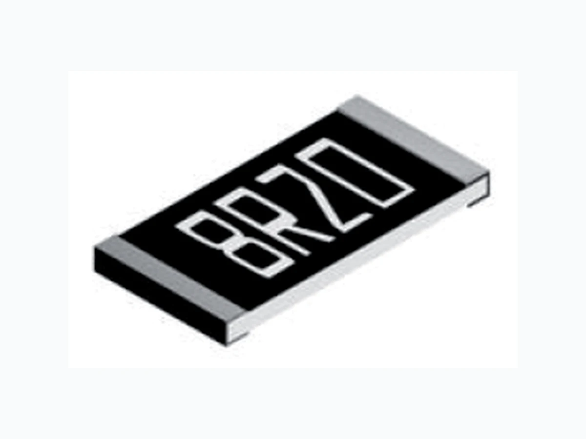
PCF0603R ETC2
Document overview
- Manufacturer or author: Provided By www.digicamel.com(FREE DATASHEET DOWNLOAD SITE)
- PDF pages: 5
Technical content
TT electronics reserves the right to make changes in product specification without notice or liability. All information is subject to TT electronics’ own data and is considered accurate at time of going to print. © TT electronics plc 1.14
- Precision thin film technology
- Extended ohmic range 1R - 3M
- Precision to ±0.01% and 5ppm/°C
- Passivated range for superior humidity performance
- Load life stability and humidity to 0.05%
- RoHS compliant Pb-free terminations A subsidiary of TT electronics plc 03.11 General Note Welwyn Components reserves the right to make changes in product specification without notice or liability. All information is subject to Welwyn’s own data and is considered accurate at time of going to print. © Welwyn Components Limited Bedlington Northumberland NE22 7AA, UK Telephone: +44 (0) 1670 822181 Facsimile: +44 (0) 1670 829465 Email: info@welwyn-tt.com Website: www.welwyn-tt.com Precision Surface Mount Resistors Precision metal film technology Extended ohmic range 1R - 3M Precision to ±0.01% and 5ppm/°C TCR grades 50, 25, 15, 10, 5ppm/°C Passivated range for superior humidity performance Load life stability and humidity to 0.05% Note 1: Standard values E24 or E96. Other values may be available by request. Note 2: Higher values available on request. Electrical Data - Standard Range PCF Series Type TCR (ppm/ºC) Power (W) Limiting Element Voltage (V) Ohmic Value Range1 PCF0201 50 0.031 15 49R9-33K -25 49R9-5K PCF0402 0.063 25 10R-205K -25 49R9-33K 10 49R9-12K 5 49R9-5K PCF0603 0.063 50 2R-1M 4R7-1M 4R7-332K -25 - 4R7-332K 24R9-100K10 5 24R9-15K PCF0805 0.1 100 1R-2M 4R7-2M 4R7-511K -25 - 4R7-511K 24R9-200K10 5 24R9-30K 2 24R9-30K PCF1206 0.125 150 1R–2M5 4R7-2M5 4R7-511K -25 - 4R7-1M 24R9-500K10 5 24R9-50K 2 24R9-50K PCF1210 0.2 150 1R–2M5 4R7-2M5 4R7-1M -25 - 4R7-1M 24R9-500K10 5 24R9-50K 2 24R9-50K PCF2010 0.25 150 1R–3M 4R7-3M 4R7-1M -25 - 4R7-1M 24R9-500K10 5 24R9-100K PCF2512 0.5 150 1R–3M 4R7-3M 4R7-1M -25 - 4R7-1M 24R9-500K10 5 24R9-100K
TT electronics reserves the right to make changes in product specification without notice or liability. All information is subject to TT electronics’ own data and is considered accurate at time of going to print. © TT electronics plc 1.14 Construction A thin-film material is selectively deposited on a 96% alumina substrate together with metallic contacts at each end of the resistor. The unadjusted resistors are heat treated to give the required TCR and stability, then a precisely controlled laser trim process adjusts the resistance value. Epoxy protection is applied and wrap-around terminations are added and plated with Nickel then Tin. Each resistor is measured immediately before packing into tape. Terminations The chips are supplied with 100% Sn matte plated wrap-around terminations suitable for soldering. * Standard values E24 or E96. Other values may be available by request. Precision Surface Mount Resistors W 0.3 ± 0.05 0.5 ± 0.05 0.8 ± 0.2 1.25 ± 0.2 1.6 ± 0.2 2.6 ± 0.2 2.4 ± 0.2 3.1 ± 0.2 L 0.6 ± 0.05 1.0 ± 0.05 1.6 ± 0.2 2.0 ± 0.2 3.2 ± 0.2 3.2 ± 0.2 4.9 ± 0.2 6.3 ± 0.2 Tmax 0.26 0.40 0.55 0.65 0.65 0.50 0.65 0.65 A 0.12 ± 0.05 0.2 ± 0.1 0.3 ± 0.2 0.4 ± 0.2 0.5 ± 0.2 0.45 ± 0.2 0.5 ± 0.2 0.5 ± 0.2 C 0.12 ± 0.05 0.2 ± 0.1 0.3 ± 0.2 0.4 ± 0.2 0.5 ± 0.2 0.5 ± 0.2 0.6 ± 0.2 0.6 ± 0.2 T WA A L Wrap-around terminations (3 faces) C 0201 0402 0603 0805 1206 1210 2010 2512 Dimensions (mm) & Weight (mg) Wt PCF Series Physical Data Electrical Data - High Power Range Electrical Data - Passivated Range Type TCR (ppm/ºC) Power (W) Limiting Element Voltage (V) Ohmic Value Range PCF0603H 0.1 75 4R7-332K 24R9-100K25 5 24R9-15K PCF0805H 0.125 150 4R7-1M 4R7-511K 24R9-200K25 10 4R7-511K 5 24R9-30K PCF1206H 0.25 200 4R7-1M 24R9-500K25 5 24R9-50K PCF1210H 0.33 200 4R7-1M 24R9-500K25 5 24R9-50KType TCR (ppm/ºC) Power (W) Limiting Element Voltage (V) Ohmic Value Range * PCF0402P 0.063 25 25R-25K25 15 49R9-12K PCF0603P 0.063 50 25R-332K25 15 25R-100K PCF0805P 0.1 100 10R-800K25 15 25R-200K PCF1206P 0.125 150 10R-1M25 15 25R-500K PCF2010P 0.25 150 10R-1M25 15 25R-500K PCF2512P 0.5 150 10R-1M25 15 25R-500K Type TCR (ppm/ºC) Power (W) Limiting Element Voltage (V) Ohmic Value Range * PCF0603H 0.1 75 4R7-1M 4R7-332K 24R9-100K25 15 4R7-332K10 5 24R9-15K PCF0805H 0.125 150 1R-1M 4R7–1M 4R7-511K 24R9-200K25 15 4R7-1M 10 4R7-511K 5 24R9-30K PCF1206H 0.25 200 4R7-1M 24R9-500K25 24R9-50K PCF1210H 0.33 200 4R7-1M 24R9-500K25 24R9-50K PCF2010H 0.33 200 4R7-1M 24R9-500K25 24R9-50K PCF2512H 0.75 200 1R-2K 4R7-2K 24R9-2K25 Type TCR (ppm/ºC) Power (W) Limiting Element Voltage (V) Ohmic Value Range * 0.5% 0.25% 0.1% PCF0402P 0.063 25 25R-25K25 15 49R9-12K PCF0603P 0.063 50 25R-332K25 15 25R-100K PCF0805P 0.1 100 10R-800K25 15 25R-200K PCF1206P 0.125 150 10R-1M25 15 25R-500K PCF2010P 0.25 150 10R-1M25 15 25R-500K PCF2512P 0.5 150 10R-1M25 15 10R-1M Type TCR (ppm/ºC) Power (W) Limiting Element Voltage (V) Ohmic Value Range * PCF0603X 50 0.166 100 10R-332K25 PCF0805X 50 0.25 150 10R-500K25 PCF1206X 50 0.333 200 10R-1M25 PCF2512X 50 1 200 1R-100R 4R7-100R25 * Standard values E24 or E96. Other values may be available by request. Electrical Data - High Power Range Electrical Data - Extended High Power Range Electrical Data - Passivated Range * Standard values E24 or E96. Other values may be available by request.
TT electronics reserves the right to make changes in product specification without notice or liability. All information is subject to TT electronics’ own data and is considered accurate at time of going to print. © TT electronics plc 1.14 Precision Surface Mount Resistors 03.11 © Welwyn Components Limited Bedlington Northumberland NE22 7AA, UK Telephone: +44 (0) 1670 822181 Facsimile: +44 (0) 1670 829465 Email: info@welwyn-tt.com Website: www.welwyn-tt.com PCF Series >0.05% tolerance 0603 to 2512 0.25% 0.3% 0.5% 0.25% 0.1% 0.2% Load life Humidity Short term overload High temperature operation Temperature cycle Resistance to solder heat Solderability Maximum change (+0.05R) Chip size 0201, 0402 0.5% 0.3% 0.5% 0.25% 0.1% 0.2% ≤0.05% tolerance 0603 to 2512 0.05% 0.05% 0.05% 0.25% 0.05% 0.05% ConditionsTest Parameters 1000 hours rated load @ 70°C 1000 hours @ 40°C, 90 - 95%RH 6.25 x rated Power , or 2 x LEV, for 5 sec 1000 hours at 125°C 5 cycles -55 C, 125°C 270°C, 10 sec 235°C, 2 sec 95% minimum coverage 0.5% 0.5% 0.5% 0.5% 0.25% 0.2% 95% minimum coverage Load life Humidity Short term overload High temperature operation Temperature cycle Resistance to solder heat Solderability Maximum change (+0.05R)ConditionsTest Parameters 1000 hours rated load @ 70°C 1000hrs @ 40°C, 90 - 95%RH 6.25 x rated Power, or 2 x LEV, for 5 sec 1000 hours at 155°C 5 cycles -55°C, 150°C 270°C, 10 sec 235°C, 2 sec 0603 to 2512 0.05% 0.05% 0.02% 0.05% 0.02% 0.02% Load life Humidity Short term overload High temperature operation Temperature cycle Resistance to solder heat Solderability Maximum change (+0.05R)ConditionsTest Parameters 1000 hours rated load @ 70°C 1000hrs @ 40°C, 90 - 95%RH 6.25 x rated Power, or 2 x LEV, for 5 sec 1000 hours at 125°C 5 cycles -55 C, 125°C 270°C, 10 sec 235°C, 2 sec 95% minimum coverage 0402 0.25% 0.5% 0.1% 0.5% 0.1% 0.1% Performance Data - Standard Range Performance Data - High Power Range/Extended High Power Range Performance Data - Passivated Range Construction A thin-film material is selectively deposited on a 96% alumina substrate together with metallic contacts at each end of the resistor. The unadjusted resistors are heat treated to give the required TCR and stability, then a precisely controlled laser trim process adjusts the resistance value. Epoxy protection is applied and wrap-around terminations are added and plated with Nickel then Tin. Each resistor is measured immediately before packing into tape. Terminations The chips are supplied with 100% Sn matte plated wrap-around terminations suitable for soldering. Physical Data Dimensions (mm) and Weight L W T max A C Wt T WA A L Wrap-around terminations (3 faces) C
TT electronics reserves the right to make changes in product specification without notice or liability. All information is subject to TT electronics’ own data and is considered accurate at time of going to print. © TT electronics plc 1.14 Wrap-around terminations provide good leach properties and ensure reliable contact. Due to the robust construction, the PCF can be immersed in the solder bath for 30 seconds at 260 C. This enables the resistor to be mounted on one side of a printed circuit board and wire-leaded components applied on the other side. PCF resistors themselves can operate at a maximum temperature of 125 C (see performance above) (155 C for High Power grades). For soldered resistors, the joint temperature should not exceed 110 C. This condition is met when the stated power levels at 70 C are used. Precision Surface Mount Resistors 03.11 © Welwyn Components Limited Bedlington Northumberland NE22 7AA, UK Telephone: +44 (0) 1670 822181 Facsimile: +44 (0) 1670 829465 Email: info@welwyn-tt.com Website: www.welwyn-tt.com PCF Series Solderability The terminations have an electroplated nickel barrier and tin coating. This ensures excellent 'leach' resistance properties and solderability. Packaging PCF Resistors are supplied taped and reeled as as per IEC 286-3. Sizes 2010 and 2512 are in embossed plastic tape. Application Notes PCF resistors are ideally suited for handling by automatic methods due to their rectangular shape and the small dimensional tolerances. Electrical connection to a ceramic substrate or to a printed circuit board can be made by reflow or wave soldering of wrap-around terminations. Derating Curve Smaller sizes are in paper tape.
TT electronics reserves the right to make changes in product specification without notice or liability. All information is subject to TT electronics’ own data and is considered accurate at time of going to print. © TT electronics plc 1.14 Ordering Procedure This product has two valid part numbers: European (Welwyn) Part Number: PCF0603-11-1K54BI (0603, standard, 15ppm/°C, 1.54 kilohm ±0.1%, Pb-free) P C F 0 6 0 3 - 1 1 - 1 K 5 4 B I 1 2 3 4 5 6 7 USA (IRC) Part Number*: PCF-W0603LF-11-1541-B-P-LT (0603, standard, 15ppm/°C, 1.54 kilohm ±0.1%, Pb-free) P C F - W 0 6 0 3 L F - 1 1 - 1 5 4 1 - B - P - L T 1 2 3 4 5 6 7 8 * Applies only to Standard Range parts. 1 2 3 4 5 6 7 Type Size Range TCR Value Tolerance Termination & Packing PCF 0201 Omit for Standard -13 = ±5ppm/°C E24 = 3/4 characters E96 = 3/4 characters R = ohms K = kilohms M = megohms L = ±0.01% Pb-free only 0402 -12 = ±10ppm/°C W = ±0.05% I = Standard Packing 0603 H = High Power -11 = ±15ppm/°C B = ±0.1% 0201, 0402 10,000/reel 0805 X = Extended R = ±25ppm/°C C = ±0.25% 0603 to 1210 5000/reel 1206 P = Passivated -02 = ±50ppm/°C D = ±0.5% 2010, 2512 4000/reel
1210 F = ±1% T1*
2010 0201 to 1206, 2010, 2512 1000/reel2512 * Non-standard; enquire to confirm availability 1 2 3 4 5 6 7 8 Type Model Termination TCR Value Tolerance Tape Packing PCF W0201 LF = Pb-free (100%Sn) 13 = ±5ppm/°C 3 digits + multiplier T = ±0.01% P = Paper (0201 to 1210) LT = Tape & Reel W0402 12 = ±10ppm/°C R = ohms for values <100 ohms A = ±0.05% 0201, 0402 10,000/reel W0603 11 = ±15ppm/°C B = ±0.1% E = Embossed (2010, 2512) 0603 to 1210 5000/reel W0805 03 = ±25ppm/°C C = ±0.25% 2010, 2512 4000/reel W1210 F = ±1% W2010 W2512