

 Download PDF
PCB-ZD ITT
Document overview
- PDF pages: 1
Technical content
Page 1
D Subminiature
Straight PCB – ZD\*
T
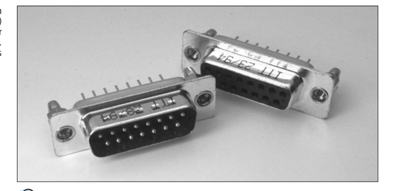
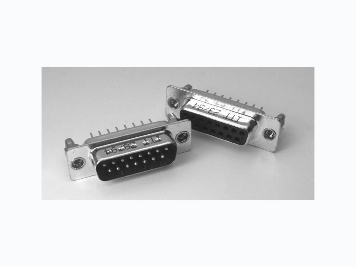
he ZD\*, straight solder termination (stamped and formed contact) connectors are available for applications where price is the primary driver. They are available with or without boardlocks and screw locks.
Applications:
- Aerospace
- Communication Systems
- Information Systems
- Medical
- Test Equipment
- Transportation
For more information: www.ittcannon.com/cat243
Product Features
- Stamped PCB contacts, 5 A current capacity. • Optional vertical standoffs with optional
- Compatible with all other D Subminiature
harpoon style boardlocks or screw locks.
series.
- Economical.
- Closed-entry socket for secure blind mating.
Performance Specifications
Connector Durability 50 mating cycles (Class 3); 200 mating cycles (Class 2) Contact Resistance 20 mΩ (on mated contacts) Contact Termination Solder, Straight PCB (stamped and formed contacts) Coupling Friction/hardware Current Rating 5 A (Standard Density) DWV 1000 V ac at sea level
Insulation Resistance 5000 MΩ to 500 V dc Number of Circuits Up to 50: 9, 15, 25, 37, 50 Operating Temperature –55°C to 105°C (–67°F to 221°F) Polarization Keystone shape of shell Shell Style 2 piece design Size or length 5 sizes – E, A, B, C, D
Materials and Finishes
Description
Material
Shell
Steel
Insulator
Thermoplastic, Glass-filled; UL 94V-0 (E112081)
Contact, Female
Phosphor Bronze
Contact, Male
Brass
Hardware
Steel or Copper Alloy
Finish Tin Color: Black Engaging Area: Gold over Nickel Terminating End: Tin Engaging Area: Gold over Nickel Terminating End: Tin Tin
Please contact your local Cannon representative: www.ittcannon.com/support/ContactUs
Dimensions are shown in mm (inch) Dimensions subject to change www.ittcannon.com
F-22
Version 05.01.03