


 Download PDF
PAH TDK
Document overview
- PDF pages: 82
Technical content
Page 1
PAH SERIES
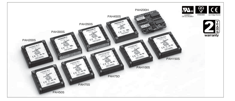
Single / Dual Output 50-450W
■ Features
- Half brick industry standard size (61×12.7×57.9 mm)
- High power density (industry-leading level in 450W
full brick model)
- High efficiency: 92% (PAH450S48)
- Wide range of operating temperatures
(Baseplate temperature: -40 to +100℃ except PAH
200H)
- Wide variation
- Built-in capacitor: Ceramic capacitor only (high reliabil- ity)
(Organic polymer semiconductor capacitor is also used
for output smoothing in PAH200H/PAH75D.)
■ Applications
■ Product Line up
CC-E
09XX
10XX
3101
KWD
PAE
PAF
■ Model naming method
PAH
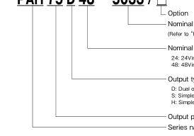
PAH 75 D 48 - 5033 / □
PAQ
Nominal output voltage (Refer to “Product Lineup”.)
PF-A
Nominal input voltage
PFE
S: Simple output H: Simple without cover
PH
Output power
PMH
■ Conformity to RoHS Directive
This means that, in conformity with EU Directive 2002/95/ EC, lead, cadmium, mercury, hexavalent chromium, and specific bromine-based flame retardants, PBB and PBDE,
have not been used, except for exempted applications.
PAH-S48 (DC48Vin)①
PAH-S24 (DC24Vin)
| Output Voltage | 300W | 350W | 300W | 350W | 450W | |||||
| Output Current | Model | Output Current | Model | Output Current | Model | Output Current | Model | Output Current | Model | |
| 12V | 25A | PAH300S24- | 12 ― | ― | 25A | PAH300S48-12 | 29.2A | PAH350S48-12 | ― | ― |
| 28V | 11A | PAH300S24- | 28 12.5A | PAH350S24-28 | 11A | PAH300S48-28 | 12.5A | PAH350S48-28 | 16A | PAH450S48-28 |
| 48V | ― | ― | 7.3A | PAH350S24-48 | ― | ― | ― | ― | 4.9A | PAH450S48-48 |
PAH-S48 (DC48Vin)②
| Output Voltage | 50W | 75W | 100W | 150W | 200W | |||||
| Output Current | Model | Output Current | Model | Output Current | Model | Output Current | Model | Output Current | Model | |
| 1.2V | ― | ― | ― | ― | ― | ― | ― | ― | 70A | PAH200H48-1R2 |
| 1.5V | ― | ― | ― | ― | ― | ― | ― | ― | 70A | PAH200H48-1R5 |
| 1.8V | ― | ― | ― | ― | ― | ― | ― | ― | 70A | PAH200H48-1R8 |
| 2.5V | 11.7A | PAH50S48-2 | .5 17.5A | PAH75S48-2.5 | 23.4A | PAH100S48-2.5 | 35A | PAH150S48-2.5 | 70A | PAH200H48-2R5 |
| 3.3V | 11.7A | PAH50S48-3 | .3 17.5A | PAH75S48-3.3 | 23.4A | PAH100S48-3.3 | 35A | PAH150S48-3.3 | 60A | PAH200H48-3R3 |
| 5V | 10.0A | PAH50S48- | 5 15.0A | PAH75S48-5 | 20.0A | PAH100S48-5 | 30A | PAH150S48-5 | ― | ― |
| 12V | 4.2A | PAH50S48-1 | 2 6.3A | PAH75S48-12 | 8.4A | PAH100S48-12 | 12.5A | PAH150S48-12 | 16.7A | PAH200S48-12 |
| 15V | 3.4A | PAH50S48-1 | 5 5A | PAH75S48-15 | 6.7A | PAH100S48-15 | 10A | PAH150S48-15 | 13.4A | PAH200S48-15 |
| 24V | 2.1A | PAH50S48-2 | 4 3.2A | PAH75S48-24 | 4.2A | PAH100S48-24 | 6.3A | PAH150S48-24 | 8.4A | PAH200S48-24 |
| 28V | 1.8A | PAH50S48-2 | 8 2.7A | PAH75S48-28 | 3.6A | PAH100S48-28 | 5.4A | PAH150S48-28 | 7.2A | PAH200S48-28 |
| 48V | ― | ― | ― | ― | ― | ― | 3.2A | PAH150S48-48 | ― | ― |
*) *) *) *) *)
*)PAH200H Serise is without cover.
PAH75D (Dual Output)
| Output Voltage | 75W | ||||||||||
| Output Current / Model | Output Current / Model | Output Current / Model | Output Current / Model | Output Current / Model | Output Current / Model | ||||||
| 1.8V | ― | PAH75D24-3325 | ― ― PAH75D24-5033 15A 15A | 15.0A | PAH75D48-2518 | 15.0A | PAH75D483-3118 | ― | PAH75D48-3325 | ― | PAH75D48-5033 |
| 2.5V | 15A | 15.0A | ― | 15.0A | ― | ||||||
| 3.3V | 15A | ― | 15.0A | 15.0A | 15.0A | ||||||
| 5V | ― | ― | ― | ― | 15.0A | ||||||
B-143 web130122
Page 2
PAH300S24
PAH300S24 Specifications
| MODEL ITEMS/UNITS | PAH300S24-12 | PAH300S24-28 | ||
|---|---|---|---|---|
| Input | Voltage Range | V | 18 - 36VDC | |
| Efficiency (typ) (*1) | % | 87 | 88 | |
| Current (typ) (*2) | A | 14.71 | 15.10 | |
| Output | Nominal Voltage | VDC | 12 | 28 |
| Maximum Current | A | 25 | 11 | |
| Maximum Power | W | 300 | 308 | |
| Voltage Setting Accuracy (*2) | % | ±1 | ||
| Maximum Line Regulation (*3) | mV | 24 | 56 | |
| Maximum Load Regulation (*4) | mV | 24 | 56 | |
| Temperature Coefficient | 0.02%/℃ | |||
| Maximum Ripple & Noise (*10) | mVp-p | 200 | 240 | |
| Voltage Adjustable Range (*10) | -40%, +10% | -40%, +18% | ||
| Function | Over Current Protection (*5) | 105% - 140% | ||
| Over Voltage Protection (*6)(*9) | 115% - 135% | 125% - 140% | ||
| Remote Sensing (*9) | Possible | |||
| Remote ON/OFF Control (*9) | Possible (SHORT : ON OPEN : OFF) | |||
| Parallel Operation (*9) | - | |||
| Series Operation (*9) | Possible | |||
| Environment | Operating Temperature (*7) | ℃ | -40 to +100(Baseplate) Ambient temperature min=-40 | |
| Storage Temperature | ℃ | -40 to +100 | ||
| Operating Humidity | %RH | 5 - 95 (No dewdrop) | ||
| Storage Humidity | %RH | 5 - 95 (No dewdrop) | ||
| Vibration | At no operating, 10-55Hz (sweep for 1min.) Amplitude 0.825mm constant (maximum 49.0m/s²) X, Y, Z 1 hour each | |||
| Shock | 196.1m/s² | |||
| Cooling (*8) | Conduction cooled | |||
| Isolation | Withstand Voltage | Input-Baseplate : 1.5kVDC, Input-Output : 1.5kVDC for 1min. Output-Baseplate : 500VDC for 1min. | ||
| Isolation Resistance | More than 100MΩ at 25℃ and 70%RH Output-Baseplate...500VDC | |||
| Standards | Safety Standards | Approved by UL60950-1, CSA C22.2 No.60950-1, EN60950-1. | ||
| Mechanical | Weight (typ) | g | 90 | |
| Size (W x H x D) | mm | 61 x 12.7 x 57.9 (Refer to outline drawing) | ||
PAH
(\*1) At 24VDC, 80% of maximum output current and baseplate temperature = +25℃. (\*2) At 24VDC and maximum output current. (\*3) 18 - 36VDC, constant load. (\*4) No load - full load, constant input voltage. (\*5) Constant current limiting with automatic recovery. (\*6) Inverter shutdown method, manual reset. (\*7) Ratings - Refer to derating curve on the right. - Load(%) is percent of maximum output current. (\*8) Heatsink has to be chosen according to instruction manual. (\*9) Refer to instruction manual. (\*10) External components are needed for operation. (Refer to basic connection and instruction manual.)
B-144
Page 3
PAH300S24
Outline Drawing
CL
SEE NOTE D
CC-E
CE- 09XX
CE- 10XX
CE- 3101
KS KWS KWD
PAE
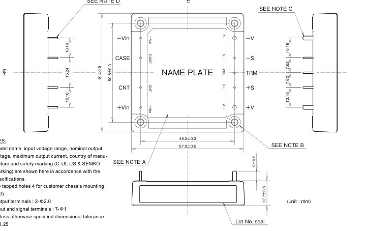
NOTES:
PAF
PAH
(FG).
PAQ
PF-A
±0.25
PFE
PH
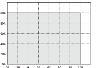
Derating Curve
PMH
-40 -20 0 20 40 60 80 100
Baseplate Temperature (℃)
B-145
Page 4
PAH350S24
PAH350S24 Specifications
| MODEL ITEMS/UNITS | PAH350S24-28 | PAH350S24-48 | ||
|---|---|---|---|---|
| Input | Voltage Range | V | DC18 - 36 | |
| Efficiency (typ) (*1) | % | 88 | 87 | |
| Current (typ) (*2) | A | 17.36 | ||
| Output | Nominal Voltage | VDC | 28 | 48 |
| Maximum Current | A | 12.5 | 7.3 | |
| Maximum Power | W | 350 | 350.4 | |
| Voltage Setting Accuracy (*2) | % | ±1 | ||
| Maximum Line Regulation (*3) | mV | 56 | 96 | |
| Maximum Load Regulation (*4) | mV | 56 | 96 | |
| Temperature Coefficient | 0.02%/℃ | |||
| Maximum Ripple & Noise (*10) | mVp-p | 280 | 480 | |
| Voltage Adjustable Range (*10) | -40%, +18% | -40%, +10% | ||
| Function | Over Current Protection (*5) | 105% - 140% | ||
| Over Voltage Protection (*6)(*9) | 125% - 140% | 115% - 140% | ||
| Remote Sensing (*9) | Possible | |||
| Remote ON/OFF Control (*9) | Possible (SHORT : ON OPEN : OFF) | |||
| Parallel Operation (*9) | - | |||
| Series Operation (*9) | Possible | |||
| Environment | Operating Temperature (*7) | ℃ | -40 to +100(Baseplate) Ambient temperature min=-40 | |
| Storage Temperature | ℃ | -40 to +100 | ||
| Operating Humidity | %RH | 5 - 95 (No dewdrop) | ||
| Storage Humidity | %RH | 5 - 95 (No dewdrop) | ||
| Vibration | At no operating, 10-55Hz (sweep for 1min.) Amplitude 0.825mm constant (maximum 49.0m/s²) X, Y, Z 1 hour each | |||
| Shock | 196.1m/s² | |||
| Cooling (*8) | Conduction cooled | |||
| Isolation | Withstand Voltage | Input-Baseplate : 1.5kVDC, Input-Output : 1.5kVDC for 1min. Output-Baseplate : 500VDC for 1min. | ||
| Isolation Resistance | More than 100MΩ at 25℃ and 70%RH Output-Baseplate...500VDC | |||
| Standards | Safety Standards | Approved by UL60950-1, CSA - C22.2 No.60950-1, EN60950-1. | ||
| Mechanical | Weight (typ) | g | 100 | |
| Size (W x H x D) | mm | 61 x 12.7 x 57.9 (Refer to outline drawing) | ||
CC-E
CE- 09XX
CE- 10XX
CE- 3101
KS KWS KWD
PAE
PAF
PAH
PAQ
PF-A
PFE
PH
PMH
(\*1) At 24VDC, 80% of maximum output current and baseplate temperature = +25℃. (\*2) At 24VDC and maximum output current. (\*3) 18 - 36VDC, constant load. (\*4) No load - full load, constant input voltage. (\*5) Constant current limiting with automatic recovery. (\*6) Inverter shutdown method, manual reset. (\*7) Ratings - Refer to derating curve on the right. - Load(%) is percent of maximum output current. (\*8) Heatsink has to be chosen according to instruction manual. (\*9) Refer to instruction manual. (\*10) External components are needed for operation. (Refer to basic connection and instruction manual.)
B-146
Page 5
PAH350S24
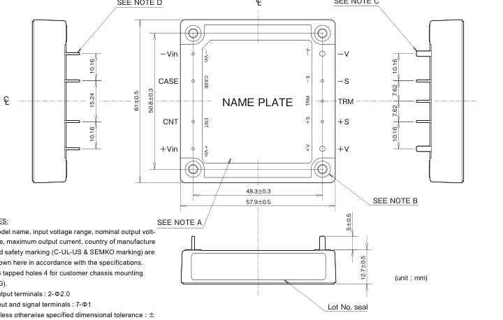
Outline Drawing
CL
SEE NOTE C
SEE NOTE D
CC-E
CE- 09XX
CE- 10XX
CE- 3101
KS KWS KWD
PAE
PAF
NOTES:
PAH
PAQ
(FG).
PF-A
0.25
PFE
PH
Derating Curve
PMH
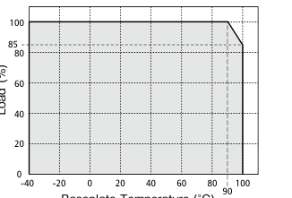
Baseplate Temperature (°C)
B-147
Page 6
PAH50S48
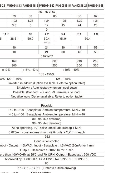
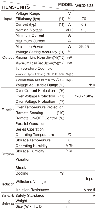
PAH50S48 Specifications
PAH50S48
PAH
(\*1) At 48 VDC, maximum output power and baseplate temperature = +25℃. (\*2) Additional external components have to be connected; refer to application notes. (\*3) External components are needed; Refer to basical connection drawing. (\*4) 36 - 76 VDC, constant load. (\*5) No load - full load, constant input voltage. (\*6) Current limiting with automatic recovery. (\*7) CNT reset or manual reset. (\*8) Refer to application notes. (\*9) Heatsink has to be chosen according to application notes. (\*10) If remote sensing is not required, connect +S and -S to +V and -V respectively (Refer to basical connection). (\*12) For -40℃ to -20℃ operation, the regulation for output 2.5V, 3.3V, 5V, 12V AND
15V is 40 mV.
B-148
Option table:
| Option | ON/OFF Logic | OVP |
| Standard | Negative (H: OFF, L: ON) | Shut-down (ON/OFF control reset or manual reset) |
| /P | Positive (H: ON, L: OFF) | |
| /V | Negative (H: OFF, L: ON) | Auto restart |
| /PV | Positive (H: ON, L: OFF) |
Example: PAH50S48-5/P represent positive logic & OVP shut-down
Page 7
PAH50S48
t ine
a in
【PAH50S】
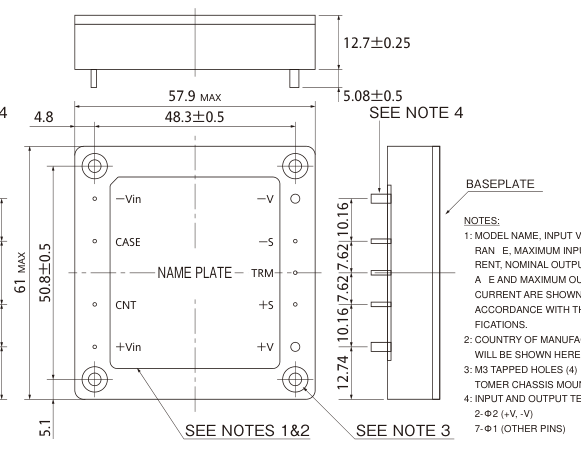
SEE NOTE 4
PAH
(unit : mm)
e atin
e
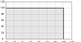
-40 -20 0 20 40 60 80 100 120
Baseplate Temperature (℃)
B-149
Page 8
PAH75S48
PAH 5S48 Specifications
PAH75S48
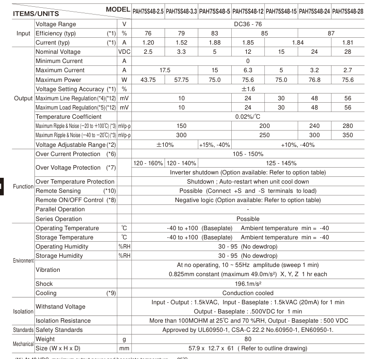
CC-E
CE- 09XX
CE- 10XX
CE- 3101
KS KWS KWD
PAE
PAF
PAH
PAQ
PF-A
PFE
PH
PMH
(\*1) At 48 VDC, maximum output power and baseplate temperature = +25℃. (\*2) Additional external components have to be connected; Refer to application notes. (\*3) External components are needed; Refer to basical connection drawing. (\*4) 36 - 76 VDC, constant load. (\*5) No load - full load, constant input voltage. (\*6) Current limiting with automatic recovery. (\*7) CNT reset or manual reset. (\*8) Refer to application notes. (\*9) Heatsink has to be chosen according to application notes. (\*10) If remote sensing is not required, connect +S and -S to +V and -V respectively (Refer to basical connection). (\*12) For -40℃ to -20℃ operation, the regulation for output 2.5V, 3.3V, 5V, 12V and
15V is 40 mV.
B-150
Option table:
| Option | ON/OFF Logic | OVP |
| Standard | Negative (H: OFF, L: ON) | Shut-down (ON/OFF control reset or manual reset) |
| /P | Positive (H: ON, L: OFF) | |
| /V | Negative (H: OFF, L: ON) | Auto restart |
| /PV | Positive (H: ON, L: OFF) |
Example: PAH75S48-5/P represent positive logic & OVP shut-down
Page 9
PAH75S48
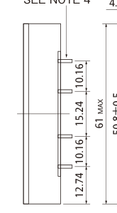
t ine
a in
【PAH75S48】
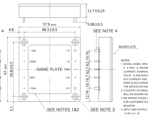
CC-E
CE- 09XX
SEE NOTE 4
CE-
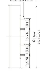
10XX
CE- 3101
KS KWS KWD
PAE
E, MAXIMUM INPUT
E AND MAXIMUM OUT-
PAF
PAH
PAQ
PF-A
7-Φ1(OTHER PINS)
PFE
(unit : mm)
PH
PMH
e atin
e
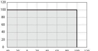
-40 -20 0 20 40 60 80 100 120
Baseplate Temperature (℃)
B-151
Page 10
PAH100S48
PAH 00S48 Specifications
PAH100S48
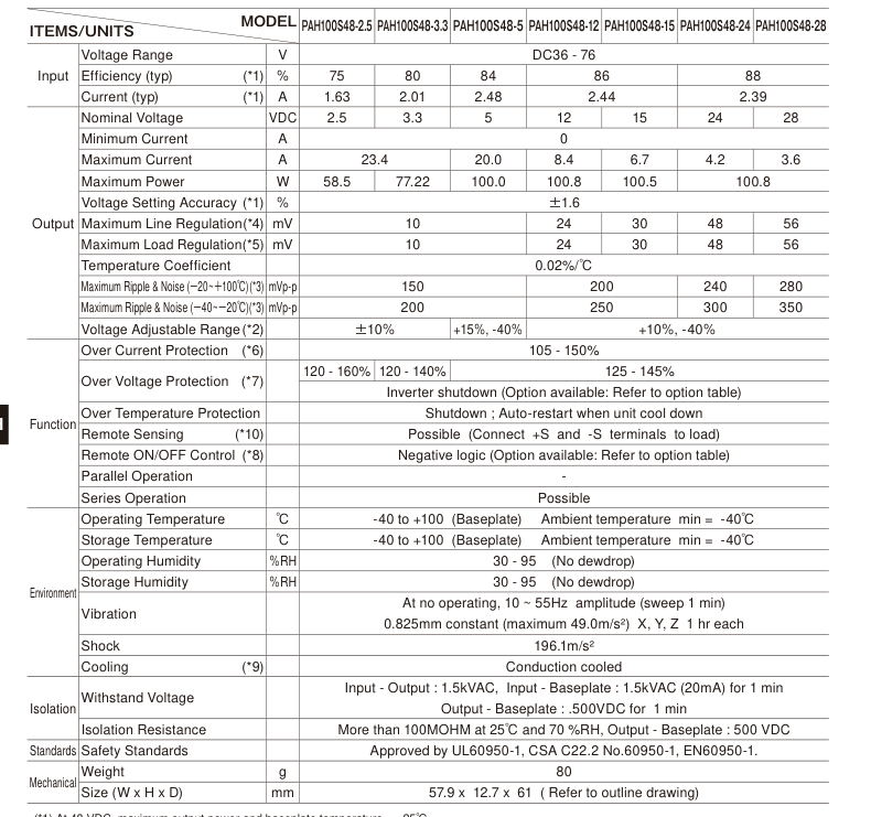
CC-E
CE- 09XX
CE- 10XX
CE- 3101
KS KWS KWD
PAE
PAF
PAH
PAQ
PF-A
PFE
PH
PMH
(\*1) At 48 VDC, maximum output power and baseplate temperature = +25℃. (\*2) Additional external components have to be connected; Refer to application notes. (\*3) External components are needed; Refer to basical connection drawing. (\*4) 36 - 76 VDC, constant load. (\*5) No load - full load, constant input voltage. (\*6) Current limiting with automatic recovery. (\*7) CNT reset or manual reset. (\*8) Refer to application notes. (\*9) Heatsink has to be chosen according to application notes. (\*10) If remote sensing is not required, connect +S and -S to +V and -V respectively (Refer to basical connection.)
B-152
Option table:
| Option | ON/OFF Logic | OVP |
| Standard | Negative (H: OFF, L: ON) | Shut-down (ON/OFF control reset or manual reset) |
| /P | Positive (H: ON, L: OFF) | |
| /V | Negative (H: OFF, L: ON) | Auto restart |
| /PV | Positive (H: ON, L: OFF) |
Example: PAH100S48-5/P represent positive logic & OVP shut-down
Page 11
PAH100S48
t ine
a in
【PAH100S48】
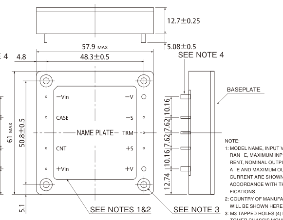
CC-E
CE- 09XX
SEE NOTE 4
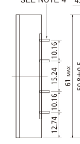
CE- 10XX
CE- 3101
KS KWS KWD
PAE
PAF E
PAH
PAQ
PF-A
TOMER CHASSIS MOUNTIN . 4: INPUT AND OUTPUT TERMINAL :
PFE
2-Φ2 (+V, -V) 7-Φ1 (OTHER PINS)
PH
(unit : mm)
PMH
e atin
e
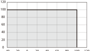
-40 -20 0 20 40 60 80 100 120
Baseplate Temperature (℃)
B-153
Page 12
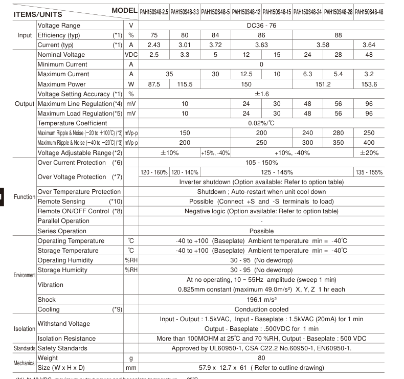
PAH150S48
PAH 50S48 Specifications
PAH150S48
CC-E
CE- 09XX
CE- 10XX
CE- 3101
KS KWS KWD
PAE
PAF
PAH
PAQ
PF-A
PFE
PH
PMH
(\*1) At 48 VDC, maximum output power and baseplate temperature = +25℃. (\*2) Additional external components have to be connected; Refer to application notes. (\*3) External components are needed; Refer to basical connection drawing. (\*4) 36 - 76 VDC, constant load. (\*5) No load - full load, constant input voltage. (\*6) Current limiting with automatic recovery. (\*7) CNT reset or manual reset. (\*8) Refer to application notes. (\*9) Heatsink has to be chosen according to application notes. (\*10) If remote sensing is not required, connect +S and -S to +V and -V respectively (Refer to basical connection.)
B-154
Option table:
| Option | ON/OFF Logic | OVP |
| Standard | Negative (H: OFF, L: ON) | Shut-down (ON/OFF control reset or Manual reset) |
| /P | Positive (H: ON, L: OFF) | |
| /V | Negative (H: OFF, L: ON) | Auto restart |
| /PV | Positive (H: ON, L: OFF) |
Example: PAH150S48-5/P represent positive logic & OVP shut-down
Page 13
PAH150S48
t ine
a in
【PAH150S48】
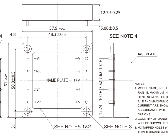
CC-E
CE- 09XX
SEE NOTE 4
CE-
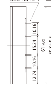
10XX
CE- 3101
KS KWS KWD
PAE
E PAF
E, MAXIMUM INPUT CUR-
PAH
ACCORDANCE WITH THE SPECIFI-
PAQ
PF-A
TOMER CHASSIS MOUNTIN . 4: INPUT AND OUTPUT TERMINAL :
PFE
2-Φ2 (+V, -V) 7-Φ1 (OTHER PINS)
(unit:mm)
PH
PMH
e atin
e
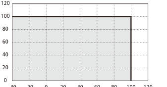
-40 -20 0 20 40 60 80 100 120
Baseplate Temperature (℃)
B-155
Page 14
PAH200S48
PAH 00S48 Specifications
PAH200S48
| MODEL ITEMS/UNITS | PAH200S48-12 | PAH200S48-15 | PAH200S48-24 | PAH200S48-28 | ||
|---|---|---|---|---|---|---|
| Input | Voltage Range | V | DC36 - 76 | |||
| Efficiency (typ) (*1) | % | 85 | 87 | |||
| Current (typ) (*1) | A | 4.91 | 4.92 | 4.82 | ||
| Output | Nominal Voltage | VDC | 12 | 15 | 24 | 28 |
| Minimum Current | A | 0 | ||||
| Maximum Current | A | 16.7 | 13.4 | 8.4 | 7.2 | |
| Maximum Power | W | 200.4 | 201.0 | 201.6 | ||
| Voltage Setting Accuracy (*1) | % | ±1.6 | ||||
| Maximum Line Regulation (*4) | mV | 24 | 30 | 48 | 56 | |
| Maximum Load Regulation (*5) | mV | 24 | 30 | 48 | 56 | |
| Temperature Coefficient | 0.02%/℃ | |||||
| Maximum Ripple & Noise (-20 to +100℃) (*3) | mVp-p | 200 | 240 | 280 | ||
| Maximum Ripple & Noise (-40 to -20℃) (*3) | mVp-p | 250 | 300 | 350 | ||
| Voltage Adjustable Range (*2) | +10%, -40% | |||||
| Function | Over Current Protection (*6) | 105 -150% | ||||
| Over Voltage Protection (*7) | 125 - 145% Inverter shutdown (Option available: Refer to option table) | |||||
| Over Temperature Protection | Shutdown ; Auto-restart when unit cool down | |||||
| Remote Sensing (*10) | Possible (Connect +S and -S terminals to load) | |||||
| Remote ON/OFF Control (*8) | Negative logic (Option available: Refer to option table) | |||||
| Parallel Operation | - | |||||
| Series Operation | Possible | |||||
| Environment | Operating Temperature (*11) | ℃ | Baseplate -40 to +80 : 100% of max. load ; min. Ta = -40 +100 : 90% of max. load | |||
| Storage Temperature | ℃ | -40 to +100 (Baseplate) Ambient temperature min = -40 | ||||
| Operating Humidity | %RH | 30 - 95 (No dewdrop) | ||||
| Storage Humidity | %RH | 30 - 95 (No dewdrop) | ||||
| Vibration | At no operating, 10 - 55Hz amplitude (sweep 1 min) 0.825mm Constant (maximum 49.0m/s²) X, Y, Z 1 hr each | |||||
| Shock | 196.1m/s² | |||||
| Cooling (*9) | Conduction cooled | |||||
| Isolation | Withstand Voltage | Input - Output : 1.5kVAC, Input - Baseplate : 1.5kVAC (20mA) for 1 min Output - Baseplate : .500VDC for 1 min | ||||
| Isolation Resistance | More than 100MOHM at 25℃ and 70 %RH, Output - Baseplate : 500 VDC | |||||
| Standards | Safety Standards | Approved by UL60950-1, CSA C22.2 No.60950-1, EN60950-1. | ||||
| Mechanical | Weight | g | 80 | |||
| Size (W x H x D) | mm | 57.9 x 12.7 x 61 (Refer to outline drawing) | ||||
CC-E
CE- 09XX
CE- 10XX
CE- 3101
KS KWS KWD
PAE
PAF
PAH
PAQ
PF-A
PFE
PH
PMH
(\*1) At 48 VDC, maximum output power and baseplate temperature = +25℃. (\*2) Additional external components have to be connected; Refer to application notes. (\*3) External components are needed; Refer to basical connection drawing. (\*4) 36 ~ 76 VDC, constant load. (\*5) No load ~ full load, constant input voltage. (\*6) Current limiting with automatic recovery. (\*7) CNT reset or manual reset. (\*8) Refer to application notes. (\*9) Heatsink has to be chosen according to application notes. (\*10) If remote sensing is not required, connect +S and -S to +V and -V respectively (Refer to basical connection.) (\*11) Refer to output derating curve.
B-156
Option table:
| Option | ON/OFF Logic | OVP |
| Standard | Negative (H: OFF, L: ON) | Shut-down (ON/OFF control reset or manual reset) |
| /P | Positive (H: ON, L: OFF) | |
| /V | Negative (H: OFF, L: ON) | Auto restart |
| /PV | Positive (H: ON, L: OFF) |
Example: PAH200S48-5/P represent positive logic & OVP shut-down
Page 15
PAH200S48
(ii) PAH200S48
t ine
a in
【PAH200S48】
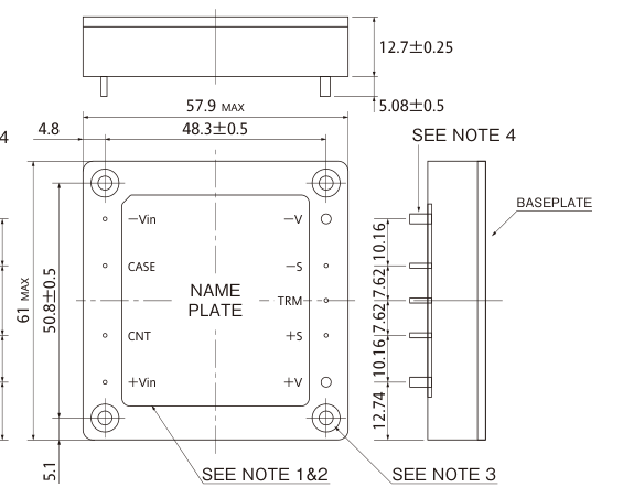
CC-E
CE- 09XX
SEE NOTE 4
CE-
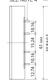
10XX
CE- 3101
KS KWS KWD
PAE
PAF
PAH
PAQ
PF-A
NOTES: 1: MODEL NAME, INPUT VOLTA E RAN E, MAXIMUM INPUT CURRENT, NOMINAL OUTPUT VOLTA
E AND MAXI-
PFE
MUM OUTPUT CURRENT ARE SHOWN HERE IN ACCORDANCE WITH THE SPECIFICATIONS. 2: COUNTRY OF MANUFACTURE WILL BE SHOWN HERE.
(unit : mm)
3: M3 TAPPED HOLES (4) FOR CUSTOMER CHASSIS MOUNTIN .
PH
4: INPUT AND OUTPUT TERMINAL : 2-Φ2 (+V, -V), 7-Φ1 (OTHER PINS)
PMH
e atin
e
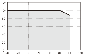
Baseplate Temperature (℃)
B-157
Page 16
PAH300S48
PAH 00S48 Specifications
PAH300S48
| MODEL ITEMS/UNITS | PAH300S48-12 | PAH300S48-28 | ||
|---|---|---|---|---|
| Input | Voltage Range | V | 36 - 76VDC | |
| Efficiency (typ) (*1) | % | 90 | ||
| Current (typ) (*2) | A | 7.02 | 7.21 | |
| Output | Nominal Voltage | V | 12 | 28 |
| Maximum Current | A | 25 | 11 | |
| Maximum Power | W | 300 | 308 | |
| Voltage Setting Accuracy (*2) | % | ±1 | ||
| Maximum Line Regulation (*3) | mV | 24 | 56 | |
| Maximum Load Regulation (*4) | mV | 24 | 56 | |
| Temperature Coefficient | 0.02%/℃ | |||
| Maximum Ripple & Noise (*10) | mVp-p | 200 | 240 | |
| Voltage Adjustable Range (*10) | -40%, +10% | -40%, +18% | ||
| Function | Over Current Protection (*5) | 105% - 140% | ||
| Over Voltage Protection (*6)(*9) | 115% - 135% | 125% - 140% | ||
| Remote Sensing (*9) | Possible | |||
| Remote ON/OFF Control (*9) | Possible (SHORT : ON OPEN : OFF) | |||
| Parallel Operation (*9) | - | |||
| Series Operation (*9) | Possible | |||
| Environment | Operating Temperature (*7) | ℃ | -40 to +100 (Baseplate) Ambient temperature min=-40 | |
| Storage Temperature | ℃ | -40 to +100 | ||
| Operating Humidity | %RH | 5 - 95 (No dewdrop) | ||
| Storage Humidity | %RH | 5 - 95 (No dewdrop) | ||
| Vibration | At no operating, 10-55Hz (sweep for 1min.) Amplitude 0.825mm constant (maximum 49.0m/s²) X, Y, Z 1 hour each | |||
| Shock | 196.1m/s² | |||
| Cooling (*8) | Conduction cooled | |||
| Isolation | Withstand Voltage | Input-Baseplate : 1.5kVDC, Input-Output : 1.5kVDC for 1min. Output-Baseplate : 500VDC for 1min. | ||
| Isolation Resistance | More than 100MΩ at 25℃ and 70%RH Output-Baseplate...500VDC | |||
| Standards | Safety Standards | Approved by UL60950-1, CSA C22.2 No.60950-1, EN60950-1. | ||
| Mechanical | Weight (typ) | g | 90 | |
| Size (W x H x D) | mm | 61 x 12.7 x 57.9 (Refer to outline drawing) | ||
CC-E
CE- 09XX
CE- 10XX
CE- 3101
KS KWS KWD
PAE
PAF
PAH
PAQ
PF-A
PFE
PH
PMH
(\*1) At 48VDC, 80% of maximum output current andbaseplate temperature = +25℃. (\*2) At 48VDC and maximum output current. (\*3) 36 - 76VDC, constant load. (\*4) No load - full load, constant input voltage. (\*5) Constant current limiting with automatic recovery. (\*6) Inverter shutdown method, manual reset. (\*7) Ratings - Refer to derating curve on the right. - Load(%) is percent of maximum output current. (\*8) Heatsink has to be chosen according to instruction manual. (\*9) Refer to instruction manual. (\*10) External components are needed for operation. (Refer to basic connection and instruction manual.)
B-158
Page 17
PAH300S48
Outline Drawing
CL
SEE NOTE D
SEE NOTE C
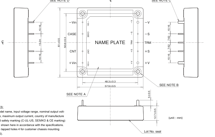
CC-E
CE- 09XX
CE- 10XX
CE- 3101
KS KWS KWD
PAE
PAF
PAH
NOTES:
PAQ
PF-A
(FG). C: Output terminals : 2-Φ2.0 D: Input and signal terminals : 7-Φ1
PFE
E: Unless otherwise specified dimensional tolerance : ±0.25
PH
Derating Curve
PMH
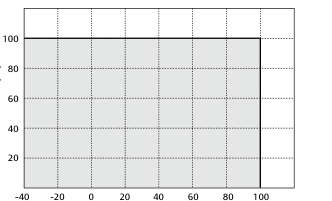
Baseplate Temperature (°C)
B-159
Page 18
PAH350S48
PAH 50S48 Specifications
PAH350S48
| MODEL ITEMS/UNITS | PAH350S48-12 | PAH350S48-28 | ||
|---|---|---|---|---|
| Input | Voltage Range | V | 36 - 76VDC | |
| Efficiency (typ) (*1) | % | 89 | ||
| Current (typ) (*2) | A | 8.25 | 8.24 | |
| Output | Nominal Voltage | V | 12 | 28 |
| Maximum Current | A | 29.2 | 12.5 | |
| Maximum Power | W | 350.4 | 350 | |
| Voltage Setting Accuracy (*2) | % | ±1 | ||
| Maximum Line Regulation (*3) | mV | 24 | 56 | |
| Maximum Load Regulation (*4) | mV | 24 | 56 | |
| Temperature Coefficient | 0.02%/℃ | |||
| Maximum Ripple & Noise (*10) | mVp-p | 200 | 280 | |
| Voltage Adjustable Range (*10) | -40%, +10% | -40%, +18% | ||
| Function | Over Current Protection (*5) | 105% - 140% | ||
| Over Voltage Protection (*6)(*9) | 115% - 135% | 125% - 140% | ||
| Remote Sensing (*9) | Possible | |||
| Remote ON/OFF Control (*9) | Possible (SHORT : ON OPEN : OFF) | |||
| Parallel Operation (*9) | - | |||
| Series Operation (*9) | Possible | |||
| Environment | Operating Temperature (*7) | ℃ | -40 to +100 (Baseplate) Ambient temperature min=-40 | |
| Storage Temperature | ℃ | -40 to +100 | ||
| Operating Humidity | %RH | 5 - 95 (No dewdrop) | ||
| Storage Humidity | %RH | 5 - 95 (No dewdrop) | ||
| Vibration | At no operating, 10-55Hz (sweep for 1min.) Amplitude 0.825mm constant (maximum 49.0m/s²) X, Y, Z 1 hour each | |||
| Shock | 196.1m/s² | |||
| Cooling (*8) | Conduction cooled | |||
| Isolation | Withstand Voltage | Input-Baseplate : 1.5kVDC, Input-Output : 1.5kVDC for 1min. Output-Baseplate : 500VDC for 1min. | ||
| Isolation Resistance | More than 100MΩ at 25℃ and 70%RH Output-Baseplate...500VDC | |||
| Standards | Safety Standards | Approved by UL60950-1, CSA C22.2 No.60950-1, EN60950-1. | ||
| Mechanical | Weight (typ) | g | 100 | |
| Size (WxHxD) | mm | 61 x 12.7 x 57.9 (Refer to outline drawing) | ||
CC-E
CE- 09XX
CE- 10XX
CE- 3101
KS KWS KWD
PAE
PAF
PAH
PAQ
PF-A
PFE
PH
PMH
(\*1) At 48VDC, 80% of maximum output current and baseplate temperature = +25℃. (\*2) At 48VDC and maximum output current. (\*3) 36 - 76VDC, constant load. (\*4) No load - full load, constant input voltage. (\*5) Constant current limiting with automatic recovery. (\*6) Inverter shutdown method, manual reset. (\*7) Ratings - Refer to derating curve on the right. - Load(%) is percent of maximum output current. (\*8) Heatsink has to be chosen according to instruction manual. (\*9) Refer to instruction manual. (\*10) External components are needed for operation. (Refer to basic connection and instruction manual.)
B-160
Page 19
PAH350S48
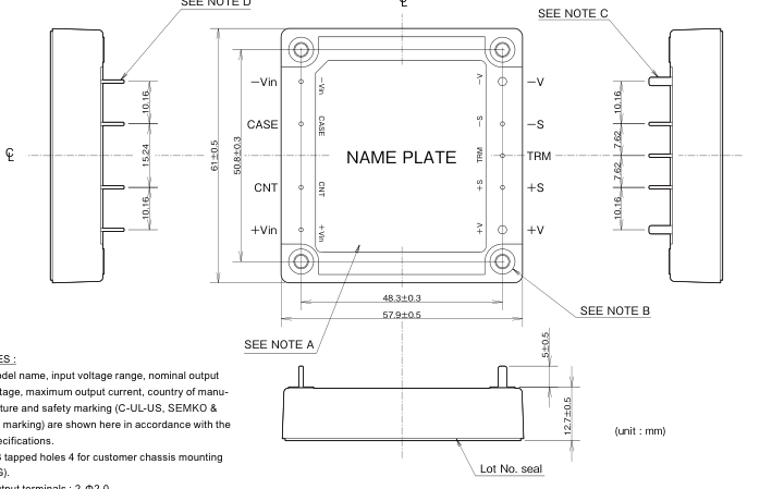
Outline Drawing
CL
SEE NOTE D
CC-E
CE- 09XX
CE- 10XX
CE- 3101
KS KWS KWD
PAE
PAF
NOTES :
PAH
PAQ
(FG).
PF-A
C: Output terminals : 2-Φ2.0 D: Input and signal terminals : 7-Φ1 E: Unless otherwise specified dimensional tolerance :
PFE
±0.25
PH
Derating Curve
PMH
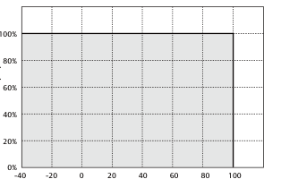
Baseplate Temperature (℃)
B-161
Page 20
PAH450S48
PAH450S48 Specifications
| MODEL ITEMS/UNITS | PAH450S48-28 | PAH450S48-48 | ||
|---|---|---|---|---|
| Input | Voltage Range | V | 36 - 76 VDC | |
| Efficiency (typ) (*1) | % | 92 | ||
| Current (typ) (*2) | A | 10.3 | 10.4 | |
| Output | Nominal Voltage | VDC | 28 | 48 |
| Maximum Current | A | 16 | 9.4 | |
| Maximum Power | W | 448 | 451.2 | |
| Voltage Setting Accuracy (*2) | % | ±1 | ||
| Maximum Line Regulation (*3) | mV | 56 | 96 | |
| Maximum Load Regulation (*4) | mV | 56 | 96 | |
| Temperature Coefficient | 0.02%/℃ | |||
| Maximum Ripple & Noise (*10) | mVp-p | 280 | 480 | |
| Voltage Adjustable Range (*10) | -40%, +18% | -40%, +20% | ||
| Function | Over Current Protection (*5) | 105% - 140% | ||
| Over Voltage Protection (*6)(*9) | 125% - 145% | |||
| Remote Sensing (*9) | Possible | |||
| Remote ON/OFF Control (*9) | Possible (SHORT : ON OPEN : OFF) | |||
| Parallel Operation (*9) | - | |||
| Series Operation (*9) | Possible | |||
| Environment | Operating Temperature (*7) | ℃ | -40 to +100 (Baseplate) Ambient temperature min=-40 | |
| Storage Temperature | ℃ | -40 to +100 | ||
| Operating Humidity | %RH | 5 - 95 (No dewdrop) | ||
| Storage Humidity | %RH | 5 - 95 (No dewdrop) | ||
| Vibration | At no operating, 10-55Hz (sweep for 1min.) Amplitude 0.825mm constant (maximum 49.0m/s²) X,Y,Z 1 hour each | |||
| Shock | 196.1m/s² | |||
| Cooling (*8) | Conduction cooled | |||
| Isolation | Withstand Voltage | Input-Baseplate : 1.5kVDC, Input-Output : 1.5kVDC for 1min. Output-Baseplate : 500VDC for 1min. | ||
| Isolation Resistance | More than 100MΩ at 25℃ and 70%RH Output-Baseplate...500VDC | |||
| Standards | Safety Standards | Approved by UL60950-1, CSA C22.2 No.60950-1, EN60950-1. | ||
| Mechanical | Weight (typ) | g | 100 | |
| Size (W x H x D) | mm | 61 x 12.7 x 57.9 (Refer to outline drawing) | ||
CC-E
CE- 09XX
CE- 10XX
CE- 3101
KS KWS KWD
PAE
PAF
PAH
PAQ
PF-A
PFE
PH
PMH
(\*1) At 48VDC, 80% of maximum output current and baseplate temperature = +25℃. (\*2) At 48VDC and maximum output current. baseplate temperature = +25℃. (\*3) 36 - 76VDC, constant load. (\*4) No load - full load, constant input voltage. (\*5) Constant current limiting with automatic recovery. (\*6) Inverter shutdown method, manual reset. (\*7) Ratings - Refer to derating curve on the right. - Load(%) is percent of maximum output current. - Refer to instruction manual. (\*8) Heatsink has to be chosen according to instruction manual. (\*9) Refer to instruction manual. (\*10) External components are needed for operation. (Refer to basic connection and instruction manual.)
B-162
Page 21
PAH450S48
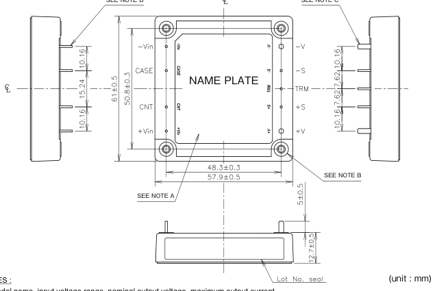
Outline Drawing
SEE NOTE C
SEE NOTE D
CC-E
CE- 09XX
CE- 10XX
CE- 3101
KS KWS KWD
PAE
PAF
PAH
NOTES :
PAQ
A: Model name, input voltage range, nominal output voltage, maximum output current, country of manufacture and safety marking (C-UL-US, SEMKO & CE marking)
PF-A
are shown here in accordance with the specifications. B: M3 threaded holes 4 for customer chassis mounting (FG). C: Output terminals : 2-Φ2.0
PFE
D: Input and signal terminals : 7-Φ1 E: Unless otherwise specified dimensional tolerance : ±0.25
PH
Derating Curve
PMH
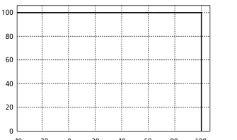
0 40 60 100
-40 -20
20
80
Baseplate Temperature(℃)
B-163
Page 22
PAH75D24
PAH 5 4 Specifications
| MODEL ITEMS/UNITS CH | PAH75D24-3325 | PAH75D24-5033 | ||||
|---|---|---|---|---|---|---|
| 1 | 2 | 1 | 2 | |||
| Input | Voltage Range | V | DC18 - 36 | |||
| Efficiency (typ) (*2) | % | 76 | 80 | |||
| Current (typ) (*2) | A | 2.71 | 3.91 | |||
| Output | Nominal Voltage | VDC | 3.3 | 2.5 | 5 | 3.3 |
| Minimum Current | A | 0.0 | ||||
| Maximum Current | A | 15 | ||||
| Maximum Power (*1) | W | Po1+Po2=60 | Po1+Po2=75 | |||
| Voltage Setting Accuracy (*2) | % | ± 2 | ||||
| Maximum Line Regulation (*5) | mV | ±6.6 | ±10 | ±6.6 | ||
| Maximum Load Regulation (*6) | mV | ±16.5 | ±25 | ±16.5 | ||
| Temperature Coefficient | 0.02 | |||||
| Maximum Ripple & Noise (*4) | mVp-p | 100 | 75 | 100 | ||
| Voltage Adjustable Range (*3) | ±10% | |||||
| Function | Over Current Protection (*7) | 105-165% Vo2 0A | 105-165% Vo1 5A | 105-165% Vo2 0A | 105-165% Vo1 5A | |
| Over Voltage Protection (*8)(*9) | 115-140% | 125-145% | 115-140% | |||
| Inverter shutdown (Option available : Refer to option table) | ||||||
| Over Temperature Protection | Shutdown ; Auto restart when unit cool down | |||||
| Remote Sensing | - | |||||
| Remote ON/OFF Control (*9) | Negative logic (Option available : Refer to option table) | |||||
| Parallel Operation | - | |||||
| Series Operation | - | |||||
| Environment | Operating Temperature | ℃ | -40 to +100 (Baseplate) Ambient temperature min = -40℃ | |||
| Storage Temperature | ℃ | -40 to +100 (Baseplate) Ambient temperature min = -40℃ | ||||
| Operating Humidity | %RH | 30 - 95 (No dewdrop) | ||||
| Storage Humidity | %RH | 30 - 95 (No dewdrop) | ||||
| Vibration | At no operating, 10 - 55HZ amplitude (sweep 1 min) 0.825mm constant (maximum 49.0m/s²) X, Y, Z 1 hr each | |||||
| Shock | 196.1 | |||||
| Cooling (*10) | Conduction cooled | |||||
| Isolation | Withstand Voltage | Input - Output : 1.5kVDC, Input - Baseplate : 1.5kVDC (20mA) for 1 min Output - Baseplate : .500VDC for 1 min | ||||
| Isolation Resistance | More than 100MOHM at 25℃ and 70 %RH, Output - Baseplate : 500 VDC | |||||
| Standards | Safety Standards | Approved by UL60950-1, CSA C22.2 No.60950-1, EN60950-1. | ||||
| Mechanical | Weight | g | 80 | |||
| Size (W x H x D) | mm | 57.9 x 12.7 x 61 (Refer to outline drawing) | ||||
CC-E
CE- 09XX
CE- 10XX
CE- 3101
KS KWS KWD
PAE
PAF
PAH
PAQ
PF-A
PFE
PH
PMH
(\*1) Combination output power for both channel. (\*2) At 24 VDC, Vo1 15A, Vo2 0A and baseplate temperature = +25℃. (\*3) Additional external components have to be connected; Refer to application notes. (\*4) Measured at Tbp=25℃, Vin=24VDC and with external components connected; Refer to basical connection drawing. For all of temperature range, please refer to the application note. (\*5) 18 - 36 VDC with respect to nominal input line 24V; constant load; baseplate temperature = +25℃. (\*6) No load - full load with respect to 50% of max. load; other output : no load ; constant input voltage; baseplate temperature = +25℃. (\*7) Current limiting with automatic recovery.
(\*8) CNT reset or manual reset. (\*9) Refer to application notes. (\*10) Heatsink has to be chosen according to application notes.
B-164
Option table:
| Option | ON/OFF Logic | OVP |
| Standard | Negative (L: ON, H: OFF) | Shut-down |
| /P | Positive (H: OFF, L: ON) | |
| /V | Negative (L: ON, H: OFF) | Auto-restart |
| /PV | Positive (H: OFF, L: ON) | Shut-down |
Example: PAH75D24-3325/PV: Represent positive logic & OVP auto-restart.
Page 23
PAH75D24
t ine
a in
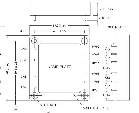
CC-E
SEE NOTE 4
CE- 09XX
CE- 10XX
CE-
10.16
3101
KS KWS KWD
15.24
PAE
10.16
PAF
12.74
PAH
PAQ
NOTE : 1. MODEL NAME, INPUT VOLTAGE RANGE, MAXIMUM INPUT CURRENT, NOMINAL
PF-A
OUTPUT VOLTAGE AND MAXIMUM OUTPUT CURRENT ARE SHOWN HERE IN ACCORDANCE WITH THE SPECIFICATIONS. 2. COUNTRY OF MANUFACTURE WILL BE SHOWN HERE.
PFE
- M3 TAPPED HOLES (4) FOR CUSTOMER CHASSIS MOUNTING. 4. INPUT AND OUTPUT TERMINAL : 10-Φ1.0
PH
e atin
e
PMH
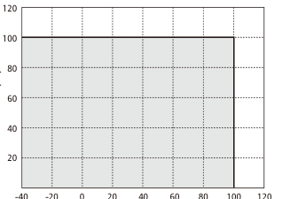
Baseplate Temperature (℃)
B-165
Page 24
PAH75D48
PAH 5 48 Specifications
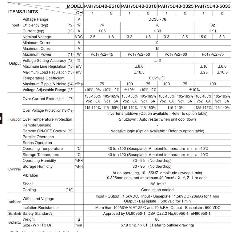
PAH
(\*1) Combination output power for both channel. (\*2) AT 48 VDC, Vo2 0A, Vo1 15 A and baseplate temperature = +25℃. (\*3) Additional external components have to be connected; Refer to application notes. (\*4) Measured at Tbp=25℃, Vin=48VDC and with external components connected; Refer to basical connection drawing. For all of temperature range, Please refer to the application note. (\*5) 36 - 76 VDC with respect to nominal input line 48 V; Constant load; baseplate temperature = +25℃. (\*6) No load - full load with respect to 50% of max. load; other output : NO load ; constant input voltage; baseplate temperature = +25℃. (\*7) Current limiting with automatic recovery.
(\*8) CNT reset or manual reset. (\*9) Refer to application notes. (\*10) Heatsink has to be chosen according to application notes.
B-166
Option table:
| Option | ON/OFF Logic | OVP |
| Standard | Negative (L: ON, H: OFF) | Shut-down |
| /P | Positive (H: ON, L: OFF) | Shut-down |
| /V | Negative (L: ON, H: OFF) | Auto restart |
| /PV | Positive (H: ON, L: OFF) | Auto restart |
EXAMPLE: PAH75D48-3325/PV: Represent positive logic & OVP auto-restart
Page 25
PAH75D48
t ine
a in
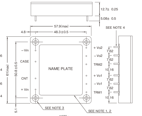
CC-E
SEE NOTE 4
CE- 09XX
CE- 10XX
CE-
10.16
3101
KS KWS
15.24
KWD
PAE
10.16
PAF
12.74
PAH
PAQ
NOTE : 1. MODEL NAME, INPUT VOLTA E RAN E, MAXIMUM INPUT CURRENT,
PF-A
NOMINAL OUTPUT VOLTA E AND MAXIMUM OUTPUT CURRENT ARE SHOWN HERE IN ACCORDANCE WITH THE SPECIFICATIONS. 2. COUNTRY OF MANUFACTURE WILL BE SHOWN HERE.
PFE
- M3 TAPPED HOLES (4) FOR CUSTOMER CHASSIS MOUNTIN . 4. INPUT AND OUTPUT TERMINAL : 10-Φ1.0
PH
PMH
e atin
e
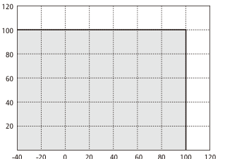
Baseplate Temperature (°C)
B-167
Page 26
PAH200H
PAH200H Specifications
PAH200H48
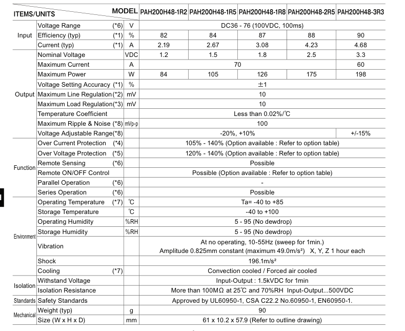
PAH
(\*1) At 48VDC, maximum output current, air velocity = 2m/s and Ta = +25℃. (\*2) 36 - 76VDC, constant load. (\*3) No load - full load, constant input voltage. (\*4) Constant current limiting. (The unit automatically shutdown when left in OCP condition with the output voltage less than the LVP level. ) Auto restart option available. (\*5) Inverter shutdown method, manual reset. Auto restart option available. (\*6) Refer to instruction manual. (\*7) Refer to derating curve and instruction manual. (\*8) External components are needed for operation. (Refer to basic connection. and instruction manual.)
■ Basic connections
Option table:
| Option | ON/OFF Logic | OVP, OCP |
| Standard | Negative (Short: ON, Open: OFF) | Shut-down (ON/OFF control reset or manual reset) |
| /V | Auto restart | |
| /P | Pogitive (Short: OFF, Open: ON) | Shut down (ON/OFF control reset or manual reset) |
| /PV | Auto restart |
Measurement point of output Measurement voltage/line regulation/load
Measurement point of maximum ripple &
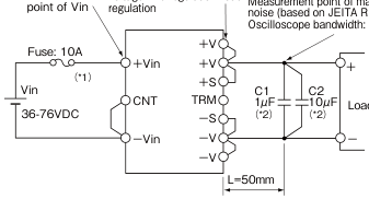
noise (based on JEITA RC-9141 probe)
(\*1) 1: The PAH200H series is not equipped with a fuse. Be sure to set a fast-blow fuse for the enhancement of safety and to get approval for safety standards. When using multiple units of the PAH200H series, set a fuse for each unit. (\*2) C1: 1µF ceramic capacitor C2: 10µF electrolytic capacitor or tantalum capacitor B-168
Page 27
PAH200H
t ine
a in
【PAH200H】
OPTION CODE
NAME
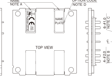
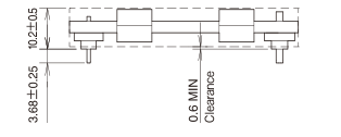
- Output derating by ambient temperature Please refer to instruction manual.
- Output derating by PCB temperature
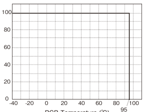
PCB Temperature (℃)
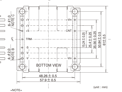
A: Model name, country of manufacture, Lot No. and safety marking (BSI, C-UL-US & CE marking) are shown here in accordance with the specifica-
PAH
tions. B: Output pin of +V and -V : 4-Φ2.0 C: Signal and Input pin : 6-Φ1.0 D: Option
| OPTION CODE | OVP/OCP | REMOTE ON/OFF CONTROL |
| NOTHIN | SHUT DOWN (ON/OFF CONT. RESET OR MANUAL RESET | NE ATIVE ) (SHORT : ON ) OPEN : OFF |
| /V | AUTO RESTART | |
| /P | SHUT DOWN (ON/OFF CONT. RESET OR MANUAL RESET | POSITIVE ) (SHORT : OFF ) OPEN : ON |
| /PV | AUTO RESTART |
tp t e atin
When using with different measurement conditions from output derating by ambient temperature, use output derating by PCB temperature. PCB temperature is decided by temperature of the component surface below. Measurement of PCB temperature is recommended to ensure the module to operate within the derating curve.
Measuring point of PCB temperature
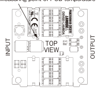
B-169
Page 28
PAH50S, 75S, 100S, 150S, 200S
oc ia
a
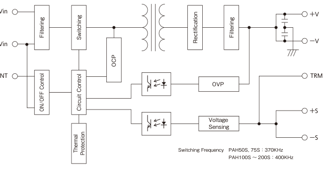
+Vin
-Vin
CNT
PAH
Se ence i
e a t
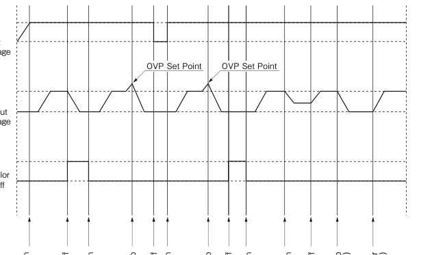
Input Voltage
Output Voltage
Contlor on/off
Note: This timing diagram is for negative logic “ON/OFF” option.
B-170
Page 29
PAH300S, 350S
oc ia
a
【PAH300S24, PAH350S24】
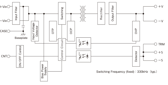
【PAH300S48, PAH350S48】
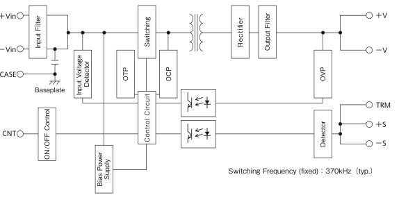
PAH
Se ence i
e a t
(For standard model with negative logic for ON/OFF control.)
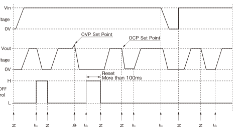
Input Voltage
Output Voltage
\*1 ON/OFF Control
\*1 level : 4≦H≦35(V) or Open 0≦L≦0.8(V) or Short
B-171
Page 30
PAH450S48
oc ia
a
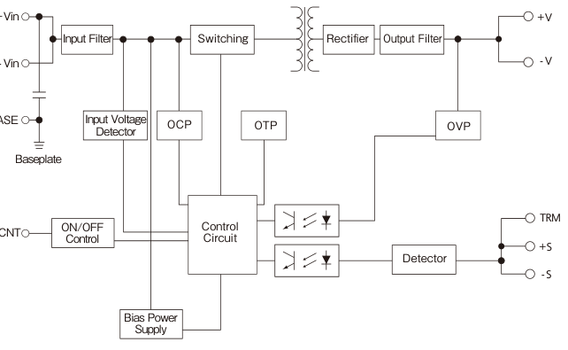
CASE
PAH
Switching Frequency (fixed) : 400kHz (typ.) for 28V Model, 460kHz (typ.) for 48V Model
Se ence i
e a t
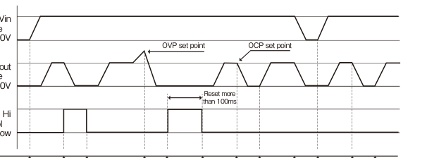
Input Voltage
Vout Output Voltage
\*1 ON/OFF Control
Input Control Control
Input Input
Control OVP Control OCP OCP
OTP OTP
ON OFF ON
OFF ON
OFF Trip
ON ON OFF
ON OFF
\*1 level : 4≦H≦35 (V) or Open 0≦L≦0.8 (V) or Short
B-172
Page 31
PAH75D
oc ia
a
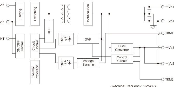
+Vin
-Vin
CNT
Se ence i
e a t
PAH
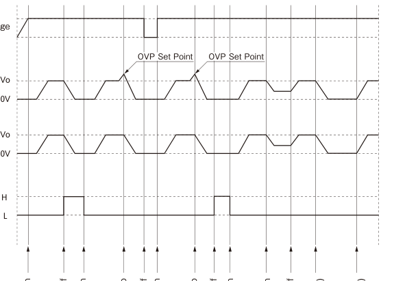
Input Voltage
Vo1
Vo2
Control ON/OFF
Note: This timing diagram is for Negative Logic "ON/OFF" Option.
B-173
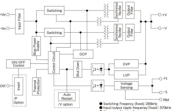
Page 32
PAH200H
oc ia
a
CC-E
CE- 09XX
CE- 10XX
CE- 3101
KS KWS KWD
PAE
PAF
PAH
- Converter Circuit : Forward type
PAQ
PF-A
Se ence i
e a t
PFE
PH (For standard model with latch type OVP and OCP, negative logic for ON/OFF control)
PMH
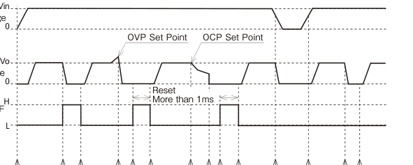
Input voltage
Output voltage
\*1 ON/OFF Control
\*1 level:4≦H≦35(V) or Open 0≦L≦0.8(V) or Short
B-174
Page 33
PAH300S24, 350S24
PAH 00 50S 4 S
S nst ction an a
- PAH50S48 ~ 200S48 Instruction Manual
B-182Page
- PAH300S48, 350S48 Instruction Manual
B-189Page
B-196Page
- PAH450S48 Instruction Manual
B-204Page
- PAH75D Instruction Manual
- PAH200H Instruction Manual
B-216Page
Before using this product
Be sure to take note of precautions and warnings indicated in this manual when using this product. Improper usage may lead to electric shock or fire. Be sure to read this instruction manual thoroughly before using this product.
Precautions
- Avoid touching the baseplate and the case of this product be- cause they get hot.
- There are high voltage and high temperature components within this product. Refrain from disassembling this product or touching its internal components as this may lead to electric shock or burn.
- To avoid unexpected accident from placing hands or face near the unit during operation.
- Confirm connections to input/output terminals and signal ter- minals are correct as indicated in the instruction manual.
- For acquisition of various Safety Standards and safety im- provement, be sure to use an external fuse.
- This product is designed for installation on electronic equip-
ment.
- For input terminals of 24 V input models, apply a voltage from a primary source with reinforced or double insulation.
- Output voltage of this product is considered to have hazard- ous energy level (voltage of 2V and above with power of 240W and above) and must not have physical contact with operator. Protection must be provided on this module when in- stalled on equipment to prevent physical contact with service technician himself or accidentally dropped tools during repair. Before repair, be sure to turn off the input source and confirm that input and output voltage have drop down to a safe level.
- Application circuit or component values described in this
PAH
instruction manual are for reference only. When designing circuit, be sure to verify actual circuit operation before determining final application circuit or component values.
- Contents of this instruction manual are subject to change without notice. When using this product, please refer to latest data sheet to satisfy this product specification.
- No part of this document may be copied or reproduced in any for, or by any mean without prior written consent of Densei- Lambda.
1. Terminal Explanation
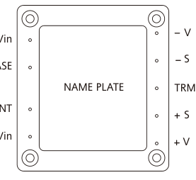
[Input Side Terminals] -Vin: -Input Terminal CASE: Baseplate Terminal
Vin
CNT: ON/OFF Control Terminal +Vin: +Input Terminal
CASE
[Output Side Terminals] -V: -Output Terminal
CNT
-S: -Remote Sensing Terminal TRM: Output Voltage Trimming Terminal
Vin
+S: +Remote Sensing Terminal +V: +Output Terminal
Baseplate can be connected to FG (frame ground) M3 threaded holes (standard model). Connect +Vin, -Vin, +V, -V with consideration of contacting resistance.
B-175
Page 34
PAH300S24, 350S24
2. Explanations on Specifications
1 Input Voltage Range
Input voltage range for PAH300, 350S24 Series is indicated below.
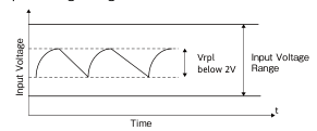
Input Voltage Range: 18 - 36VDC Basically,ripple voltage (Vrpl) which results from rectifica- tion and filtering of commercial AC line is included within the input voltage as shown in fig. 1-1. Ripple voltage must be limited within the voltage described below.
Allowable input ripple voltage: 2Vp-p When this value is exceeded, the output ripple voltage be- comes large. Note that sudden input voltage change may cause variation of output voltage transitionally. Also, input voltage waveform peak value must not exceed above input voltage range.
PAH
Fig.1-1 Input Ripple Voltage
- Basic Connection
M3 threaded hole
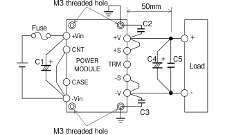
Fig.1-2 Basic Connection
Input Fuse This power module has no built-in fuse. Use external fuse to acquire various Safety Standards and to improve safety. Also, use fast-blow type for every module. Furthermore, fuse must be connected to the +Vin side if ‒ Vin side is used as ground, or fuse must be connected to ‒Vin side if +Vin side is used as a ground.
Input Fuse recommended current rating:
PAH300S24: 30A PAH350S24: 40A
C1: To prevent the effect of input line inductance to the power module, connect electrolytic capacitor or ceramic capacitor between +Vin and ‒Vin terminals. Furthermore, use electrolytic capacitor with small ESR value. Especially take note that during line turn off at low ambient temperature, power module output will not nor- B-176
mally shut down due to unstable C1 voltage. Also, ripple current flows across this capacitor. Therefore, verify maximum allowable ripple current this capacitor when selecting component. Verify actual ripple current value by actual measurement.
Recommended capacitor value: 220μF ×2pcs and above
(Parallel connect) (Voltage Rating 50V and above)
Notes 1. Use low impedance electrolytic capacitor with excellent temperature characteristics. (Nippon Chemi-con LXY Series or equivalent) 2. When input line inductance becomes excessively high due to insertion of choke coil, operation of the power module could become unstable. For this case, increase C1 value more than the value indicated above. 3. When ambient temperature becomes lower than ‒20℃, connect 4 more and above capacitors indicated above in parallel to reduce ESR.
C2, C3: 0.022μF To reduce spike noise voltage at the output, connect film capacitors or ceramic capacitors between +V and the nearest M3 threaded hole and between ‒V and the nearest M3 threaded hole. Also, take note that output spike noise voltage could vary according to PCB (printed circuit board) wiring design. However, for cases where baseplate is connected to +V or ‒V, use the nearest M3 threaded hole. (M3 threaded holes is internally connected to baseplate inside the Power Module.) For this type of connection, C2 and C3 can be omitted.
C4: For stable operation, connect an electrolytic capacitor be- tween +V and ‒V at 50mm distance from the output terminals. Take note that output ripple and output shutdown could be affected by electrolytic capacitor, equivalent impedance and inductance characteristics of wiring. Take note that output ripple voltage could vary according to PCB wiring design. For cases of abrupt changes in load current or input voltage, increasing capacitance value of the external capacitors could reduce the voltage fluctuation.
| Vout | C4 |
| 12V | 25V 470μF |
| 28V | 50V 220μF |
| 48V | 100V 120μF |
Table1-1 C4: Recommended Values of External
Output Capacitor
Notes 1. Use low impedance electrolytic capacitor with excellent temperature characteristics. (Nippon Chemi-con LXY Series or equivalent) 2. Use three capacitors indicated above in parallel when ambient temperature becomes lower than ‒20℃ to re- duce ESR.
Page 35
PAH300S24, 350S24
- Take note of the allowable ripple current of the capacitor to be used. Especially, when load adding capacitors for abrupt current changes, be sure to verify that ripple current does not exceed allowable ripple current before use.
C5: 0.1μF To reduce spike noise voltage at the output, connect a ce- ramic capacitor between +V and ‒V within 50mm distance from the output terminals. Also, take note that output spike noise voltage could vary according to PCB wiring design.
C6: When switches or connectors are used between input source and PAH300, 350S24 Series input terminals, im- pulse surge voltage is generated due to input throw-in by switch on/off or due to inserting/removing of power module from the active line. For this case, connect an additional electrolytic capacitor C6 as shown in fig.1-3 and fig. 1-4.
Recommended Capacitance Value : 220μF and above (Voltage Rating 50V and above)
Also, in-rush current flows at line throw-in. Therefore, be sure to verify capability of switch or fuse to withstand I2t at line throw-in.
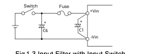
Fig.1-3 Input Filter with Input Switch
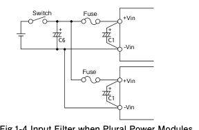
Reverse input connection Reverse input polarity would cause module damage. For cases where reverse connections are possible, connect a protective diode and fuse. Use protective diode with higher voltage rating than the input voltage, and with higher surge current rating than the fuse.
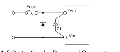
Fig.1-5 Protection for Reversed Connection of Input
- Recommended input filter as EMI countermeasure (conforms to VCCI Class 1, FCC class A) (1)Recommended input filter as EMI countermeasure
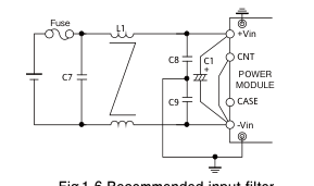
Fig.1-6 Recommended input filter as EMI countermeasure
Recommended Values: C1: 680μF (Electrolytic Capacitor) 3 pcs in parallel C7: 10μF (Ceramic Capacitor) C8,C9: 0.47μF (Film Capacitor) L1: 1mH (Common-mode choke coil)
Notes 1. For the power module output, connect output capacitors described in the basic circuit connection. 2. C1 (electrolytic capacitor) value can be reduced if im- pedance of input line is lower and operation of power module is stable. 3. VCCI Class 1, FCC Class A limits can be satisfied
PAH
with the above recommended filter at Densei-Lambda measuring conditions. However, there are cases where above limits might not be satisfied due to input and output wiring method, as well as, peripheral circuits. When selecting input filter, be sure to verify actual EMI characteristics (CE and RE) before finalizing the filter. Refer to PAH300, 350S24-* Evaluation Data for details.
2 Output Voltage Adjustment Range
Output voltage could be adjusted within the range de- scribed below by external resister or variable resistor. However, take note that OVP might trigger when output voltage adjustment exceeds the ranges indicated below.
Output Voltage Adjustment Range 12V, 48V: -40% to +10% of nominal output Voltage 28V: -40% to +18% of nominal output Voltage
When increasing the output voltage, reduce the output current accordingly so as not to exceed the maximum output power. Take note that input voltage range is limited as shown in fig.2-1 when output voltage is increased. Remote sensing is possible even when output voltage is varied. For details on remote sensing function, please refer to “9. Remote Sensing”.
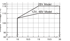
Input Voltage (VDC) Fig.2-1 Limit of Input Voltage
B-177
Page 36
PAH300S24, 350S24
- Output Voltage Adjustment by external resistor or by variable resistor
(1) In case of adjusting output voltage lower (1-1) Available maximum output current = rated output current (1-2) Connect an external resistor Radj (down) between the TRM terminal and ‒S terminal.
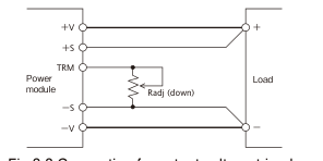
Fig.2-2 Connection for output voltage trim down
(1-3) Equation of external resistor and output voltage.
Radj (down)=〔100% -2 〕[kΩ]
Δ% Radj (down) : Value of external resistor Δ(%) : Output voltage change rate against nominal output voltage
Below graph is relation Δ(%) and value of external resistor. PAH
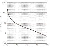
Change in Output VoltageΔ (%)
Fig.2-3 Δ(%) vs. Radj (down) (1)
(2) In case of adjusting output voltage higher (2-1) Allowable maximum output current = maximum output power ÷ output voltage (reduce maximum output current in specification.) (2-2) Connect an external resistor Radj (up) between TRM terminal and +S terminal.
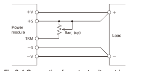
Fig.2-4 Connection for output voltage trim up
(2-3) Equation of external resistor and output voltage
Radj (up)=〔Vo (100%+Δ%) - 100%+2×Δ% 〕
[kΩ]
1.225×Δ% Δ% Vo: Nominal output value of module Radj(up): External adjustment resistor Δ(%): Output voltage change rate against nominal output voltage
Below graph is relation Δ(%) and value of external resistor.
B-178
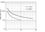
Change in Output VoltageΔ (%) Fig.2-5 Δ% vs. Radj (up) (2)
3 Maximum Ripple and Noise
Measured value according to the specified methods based on JEITA-9141 (Clause 7.12 and clause 7.13) which is de- scribed in the following. Connect according to fig.3-1 and measure. Connect capacitors (C2, C3: film capacitor or ceramic capacitor 0.022μF) between output terminals and the nearest M3 threaded hole. Connect capacitors (C4: refer to table 1-1 for electrolytic capacitor values, C5: ceramic capacitor 0.1μF) at 50mm distance from the output terminals. Measure at ceramic capacitor (C5) terminals as shown in fig. 3-1 using coaxial cable with JEITA attachment. Use oscilloscope with 100MHz frequency bandwidth or equivalent. Take note that output ripple voltage and output spike noise
may vary depending on PCB wiring design. Generally, output ripple voltage and output spike noise can be reduced by increasing capacitance value of external capacitor.
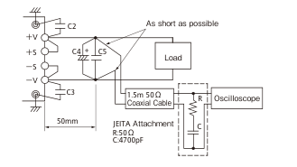
Fig.3-1 Measurement of Maximum Output Ripple & Noise
4 Maximum Line Regulation
Maximum value of output voltage change when input voltage is gradually varied (steady state) within specified input voltage range.
5 Maximum Load Regulation
Maximum value of output voltage change when output current is gradually varied (steady state) within specified output current range. When using at dynamic load mode, audible noise could be heard from the power module and output voltage fluctuation might increase. A thorough pre-evaluation must be performed before using this power module.
6 Over Current Protection (OCP)
This power module has built-in OCP function. Output will recover when short circuit or overload conditions are released. OCP setting value is fixed and therefore, cannot be externally adjusted.
Page 37
PAH300S24, 350S24
Also, take note that power module might be damaged continuing output short circuit or over load conditions depending on thermal conditions.
7 Over Voltage Protection (OVP)
This power module has built-in OVP function. OVP set point is relative to the rated output voltage value. OVP setting value is fixed and therefore, can not be externally adjusted. When OVP is triggered, output can be recovered by turning input line off and then turning it on again after lowering the input voltage below the voltage value indicated below, or by manual reset of the CNT terminal. Reset time for CNT terminal is 100ms or longer.
OVP release input voltage value: 3VDC and below
When verifying OVP function by applying external voltage at the output terminals, applied voltage value should not exceed specified OVP maximum value. Refer to specifica- tion table for OVP maximum value. Avoid applying external voltage that exceeds OVP maximum value because this will cause power module damage.
8 Over Temperature Protection (OTP)
This power module has built-in OTP function. This function operates and shuts down the output when ambient temperature or internal temperature of power module abnormally rises. OTP operates at 105℃ to 130℃ baseplate temperature. OTP can be released when baseplate temperature drops down approximately to within 80℃ to 95℃. However, take note that OTP will operate again unless the cause of abnormal heat of the power module is eliminated.
9 Remote Sensing (+S, -S terminal)
Remote sensing terminal is provided to compensate for voltage drop across the wirings from the power module output terminal to the load input terminal. When remote sensing function is not used (local sensing), short +S terminal to +V terminal and, ‒S terminal to ‒V terminal. Take note that voltage compensation range for line drop (voltage drop due to wiring) is determined such that output voltage at the output terminals is within output voltage range and that voltage between ‒V and ‒S terminals is within 2V or less. Even for remote sensing case, use power module such that output power is within specified maximum output power. Furthermore, reduce noise effect by using shield wire, twist
pair, or parallel pattern.
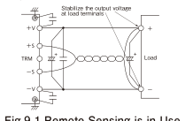
Fig.9-1 Remote Sensing is in Use
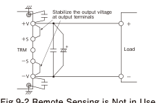
10 ON/OFF Control (CNT terminal)
Without turning the input supply on and off, the output can be enabled and disabled using this function. This function also can be used for output sequence of plural power modules. There are two kinds of logic control, negative logic control and positive logic control, depend on the option selected. ON/OFF control circuit is on the primary side (the input side). For secondary control, isolation can be achieved through the use of an opto-coupler or relay.
| Logic | CNT Terminal Level to -Vin Terminal | Output status | |
|---|---|---|---|
| Standard /T option | Negative Logic | H Level (4V≦H≦35V) or Open | OFF |
| L Level (0V≦L≦0.8V) or Short | ON | ||
| /P option /PT option | Positive Logic | H Level (4V≦H≦35V) or Open | ON |
| L Level (0V≦L≦0.8V) or Short | OFF |
PAH
Notes 1. When ON/OFF control function is not used for the Standard and /T option, CNT terminal should be shorted to ‒Vin terminal. 2. When ON/OFF control function is not used for the /P option and /PT option, CNT terminal should be opened. 3. When using long wiring, for prevention of noise, at- tach a 0.1µF capacitor between CNT terminal and ‒Vin terminal. 4. At L level, maximum source current from CNT terminal to ‒Vin terminal is 0.5mA 5. The maximum CNT terminal voltage is 35V. (1) Output ON/OFF control
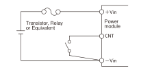
Fig.10-1 CNT Connection (1)
(2) Secondary (output side) control
| Secondary (output side) | +Vin Power module CNT -Vin |
Fig.10-2 CNT Connection (2)
11 Parallel Operation
Parallel Operation can not be used.
B-179
Page 38
PAH300S24, 350S24
12 Series Operation
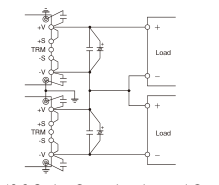
Series operation is possible for PAH300, 350S24 series. Connections shown fig. 12-1 and fig. 12-2 are possible.
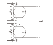
Fig.12-1 Series Operation due to High Output Voltage
PAH
Fig.12-2 Series Operation due to ±Output
13 Operating Ambient Temperature
There is no restriction on mounting direction but there should be enough consideration for airflow so that heat does not accumulate around the power module vicinity. Determine external components configuration and mounting direction on PCB such that air could flow through the heatsink at forced cooling and conventional cooling. By maintaining actual baseplate temperature below 100℃, operation is possible. For details on thermal design, refer to Application Notes “Thermal Design”.
Note : Maximum baseplate temperature is 100℃. For worst case operating condition, verify baseplate temperature at measurement point indicated in fig. 13-1.
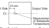
Input Side
Measurement Point
Fig.13-1 Measurement Point of Baseplate Temperature
For better improvement of power module reliability, derating of baseplate temperature when using is recommended.
14 Operating Ambient Humidity
Take note that moisture could lead to power module ab- normal operation or damage.
15 Storage Ambient Temperature
Abrupt temperature change would cause moisture formation that leads to poor solderability of each terminal of the power module.
B-180
16 Storage Ambient Humidity
Take enough care when storing the power module be- cause rust which causes poor solderability would form in each terminal when stored in high temperature, high hu- midity environment.
17 Cooling Method
Operating temperature range is specified by the baseplate temperature. Therefore, several methods of heat dissipation are possible. For details on thermal design, refer to Application Notes “Thermal Design”.
18 Baseplate Temperature vs. Output Voltage Drift
Output voltage drift is defined as the rate of voltage change when baseplate temperature only is changed during operation.
19 Withstand Voltage
This power module is designed to have a withstand voltage of 1.5kVDC between input and baseplate, 1.5kVDC between input and output and 500VDC between output and baseplate for 1 minute. When conducting withstand voltage test during incoming inspection, be sure to apply DC voltage. Also, set the current limit value of the withstand voltage testing equipment to 10mA. Be sure to avoid conducting test with AC voltage because this would cause power module damage. Furthermore, avoid throw in or shut off of the testing equipment when applying or when shutting down the test voltage. Instead, gradually increase or decrease the applied voltage. Take note especially not to use the timer of the
test equipment because when the timer switches the ap- plied voltage off, impulse voltage which has several times the magnitude of the applied voltage is generated causing damage to the power module. Connect the terminals as shown in the diagram below.
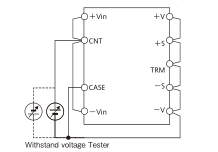
1.5kVDC 1 minute (10mA) Fig.19-1 Withstand Voltage Test for Input-Output and
Input-Baseplate
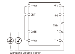
500VDC 1minute (10mA)
Fig.19-2 Withstand Voltage Test for Output-Baseplate
Page 39
PAH300S24, 350S24
20 Isolation Resistance
Use DC isolation tester (MAX 500V) between output and baseplate. Isolation resistance value is 100MΩ and above at 500VDC applied voltage. Also take note that depending on the isolation tester used, some testers generate high voltage pulse. Discharge the power module after test using a resistor, etc.
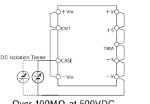
Over 100MΩ at 500VDC Fig.20-1 Isolation Test
21 Vibration
Vibration of power module is defined in case of mounting on printed circuit board.
22 Shock
Withstand shock value is defined to be the value at Densei -Lambda shipment and packaging conditions.
23 Others
Please refer to "Power Module Application Note" for thermal design and mounting direction.
3. Before concluding power module damage
Verify following items before concluding power module damage.
1)No output voltage
- Is specified input voltage applied?
- Are the ON/OFF control terminal (CNT), remote sensing terminal (+S, -S), output voltage trimming terminal (TRM) correctly connected?
- For cases where output voltage adjustment is used, is the resistor or variable resistor setting, connec- tions correctly done?
- Are there no abnormalities in the output load used?
- Is the baseplate temperature within the specified temperature range?
2)Output voltage is high
- Are the remote sensing terminals (+S, -S) correctly connected?
- Is the measurement done at the sensing points?
- For cases where output voltage adjustment is used, is the resistor or volume setting, connections cor- rectly done?
3)Output voltage is low
- Is specified input voltage applied?
- Are the remote sensing terminals (+S, -S) correctly
PAH
connected?
- Is the measurement done at the sensing points?
- For cases where output voltage adjustment is used, is the resistor or variable resistor setting, connec- tions correctly done?
- Are there no abnormalities in the output load used?
4)Load regulation and line regulation is large
- Is specified input voltage applied?
- Are the input terminals and the output terminals firmly connected?
- Is the measurement done at the sensing points?
- Is the input or output wire too thin?
5)Output ripple voltage is large
- Is the measuring method used the same or equiva- lent with the specified method in the Application Notes?
- Is the input ripple voltage value within the specified value?
B-181
Page 40
PAH 50S48~200S48
PAH S48 S
S nst
ction an a
- PAH300S24, 350S24 Instruction Manual
B-175Page
- PAH300S48, 350S48 Instruction Manual
B-189Page
B-196Page
- PAH450S48 Instruction Manual
B-204Page
- PAH75D Instruction Manual
CC-E
- PAH200H Instruction Manual
B-216Page
CE- 09XX
Before Using This Power Module
CE- 10XX Pay attention to all warnings and cautions before using this unit. Incorrect usage could lead to an electric shock, damage to the CE- unit, or a fire hazard. Be sure to read below warnings and cau- 3101 tions before using the power module. KS KWS KWD
Warning
PAE
- Do not touch heatsink and case which may be hot.
- Do not open the case and touch the internal components.
PAF They may have high temperature or high voltage which may get you in electric shock or burned.
- When the unit is operating, keep your hands and face away
PAH from the unit. You may get injured by an accident.
PAQ
Caution
- Confirm connections to input/output terminals and signal ter-
PF-A minals are correct as indicated in the instruction manual.
- Attach a fast blow type external fuse to each module to en- sure safety operation and to acquire each safety standard ap-
PFE
proval.
- This power module is designed for professional installation within an end user equipment.
- Use isolated voltage by reinforced insulation at primary power supply or double insulation as input power source.
- The output from this power module must be considered as an energy hazard (> 240VA power and 2V voltage) and must not be accessible to an end user. End equipment manufactur- ers must provide protection against inadvertent contact with the output terminals on this product by a service engineer or by service engineer dropping a tool into them.
- The application circuits and their parameter are for reference only. Be sure to verify effectiveness of application circuits and their parameters before finalizing circuit design.
- The information in this document is subject to change without notice. For actual design-in, please refer to the latest publica- tions of data sheet, etc., for the most up-to-date specifica- tions of the unit.
- No part of this document may be copied or reproduced in any form or by any mean without prior written consent of Densei- Lambda.
1. Terminal Pin Configurations
PH
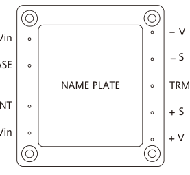
PMH
-Vin: Nagative Input Terminal
Vin
CASE: Baseplate Terminal CNT: ON/OFF Control Termina +Vin: Positive Output Terminal
CASE
-V: Negative Output Terminal -S: Negative Remote Sensing TRM: Output Voltage Adjustment Terminal +S: Positive Remote Sensing
CNT
+V: Positive Output Terminal
Vin
Output ripple and noise
Measuring point of output
measuring point probe
voltage and regulation
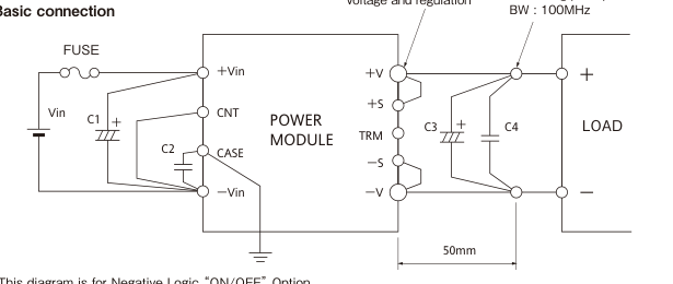
Note : This diagram is for Negative Logic “ON/OFF” Option.
B-182
Page 41
PAH 50S48~200S48
1 External Components
The table below shows the recommended values for the external components above.
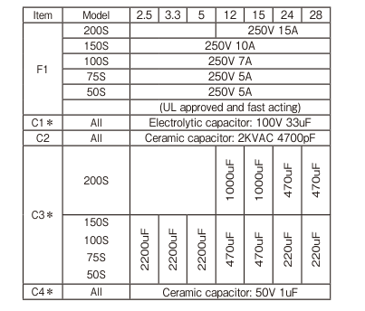
* (1) The above value is for operating temperature range from -20℃ to 100℃.
(2) For -40℃ to 100℃ range, change C1 to ceramic type of capacitor and use 2 capacitors for C3. (3) Use low ESR type E-Cap for C1 and C3 such as KME series for C1 and LXY series of Nippon Chemi-Con for C3. (4) Only for 200W model; -40℃ to 100℃ operation, C4 is increased to 10uF ceramic cap.
CC-E
PAH-S48 SERIES module is not internally fused. To en- sure safe operation and to receive each safety standard CE-
09XX
approval, please connect an external fuse, F1 as shown in the diagram above.
CE- 10XX
Input capacitor C1 is recommended to stabilize the module when the module is powered from a high impedance
CE-
source.
3101
Capacitor C2 is used to absorb noise coming from the
KS
module itself. This capacitor will also help the EMI perfor- KWS
KWD
mance of the module. The function of capacitor C3 is to reduce the output ripple
PAE
of the power module whereas the capacitor C4 is to reduce high frequency noise that is produced by the module.
PAF
If in any application where an input reversal connection is possible, a protective diode that is connected across +Vin
PAH
and ‒Vin is recommended.
2. Explanations on Specifications
1 Input Voltage Range
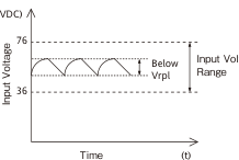
The operating input voltage range of PAH-S48 SERIES is 36~76VDC. The maximum allowable input ripple voltage (Vrpl) is 4V. Any ripple that exceeds this value might cause the module to become unstable.
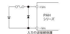
Protection for input reverse connection Please connect protection diode and a fuse as shown below.
2 Output Voltage Adjust Range
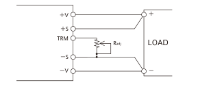
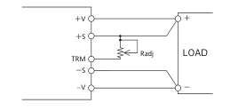
The output voltage of power module can be adjusted by connecting an external resistor (Radj) between the TRIM pin and either the +S or ‒S pins. With an external resistor (Radj) between TRIM pin and ‒S pin, output voltage will decrease
PAQ
as shown in diagram below.
PF-A
PFE
PH
PMH
The equation shown below determines the required external resistor (Radj) value to obtain a percentage output voltage change of Δ%.
Radj(down)=( )
100% -2 kΩ Δ%
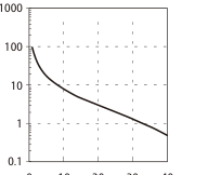
The graph shown below the external resistor (Radj) value against a percentage output voltage change of Δ%.
10 20 30 40 0 %CHANGE IN OUTPUT VOLTAGE(Δ%)
If the external resistor (Radj) is connected between the TRM pin and +S pin, the output voltage will increase. Diagram shown below is the output voltage trim up connection.
B-183
Page 42
PAH 50S48~200S48
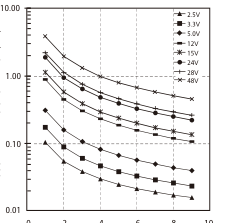
The equation shown below determines the required exter- CC-E nal resistor (Radj) value to obtain a percentage output volt- CE- age change of Δ%. 09XX
CE- 10XX
CE- Vo = Nominal output Voltage. 3101
KS KWS The graph shown is the external resistor (Radj) value against KWD a percentage output voltage change of Δ% .
PAE
PAF
PAH
PAQ
PF-A
PFE
0 2 4 6 8 10
%CHANGE IN OUTPUT VOLTAGE(%)
If the output voltage is raised above its nominal value, the PH output current needs to be derated to a value such that the output power does not exceed the maximum output power PMH specified in the specification sheet. In addition to that, there is also a limitation to the input voltage range for the 5V version only which is as shown below.
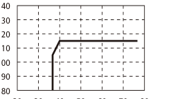
20 30 40 50 60 70 80 Input Voltage (VDC)
3 Output Ripple & Noise Measurement Method
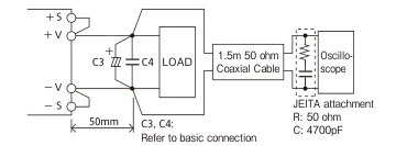
The method for output ripple and noise are based upon JEITA RC-9002A. Upon measurement of the ripple voltage, make sure that the oscilloscope probe leads are not too long.
B-184
4 Maximum Line Regulation
Maximum line regulation is the maximum output voltage change when the input voltage is slowly varied within the input voltage range. The measurement point for the input and output voltage are ±Vin and ±S (sensing point) re- spectively.
5 Maximum load regulation
Maximum load regulation is the maximum output voltage value change when varying the load current slowly within the standard output current range. The measurement point for the input and output voltages are ±Vin and ±S (sense point) respectively.
6 Brownout
There will be output voltage overshoot during brown-out (momentary input line off) condition.
7 Over Current Protection
The PAH-S48 SERIES is equipped with an over current protection circuit. When the short or overload condition is removed, the output will automatically recover. This setting is fixed and cannot be varied externally. If the short or overload condition continues, the power module could be damaged due to the heat condition.
8 Over Voltage Protection
There are 2 types of over protection method available for the PAH series. In the standard model, a latching shutdown method is adopted. For this method there are two ways to reset the power module after OVP protection triggers. They are by (i) giving a pulse to the control pin or (ii) recycling the input voltage. In the /V optional model, the power module will shutdown after OVP protection triggers but will recover automatically when over voltage is removed.
9 Thermal Protection
The PAH-S48 SERIES have a thermal protection circuit that sense the baseplate temperature between the range of 105℃ to 130℃ for an over temperature condition. Under a condition where the ambient temperature or the power module internal temperature rises excessively, the thermal protection circuit will shut down the power module. The power module will recover automatically when the baseplate temperature cools down.
10 Remote Sensing
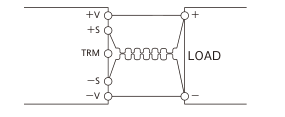
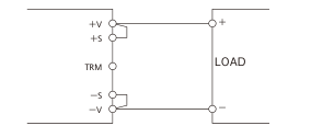
The PAH-S48 SERIES is equipped with remote sensing terminals, which compensate for the voltage drops between the power supply output terminals and the load terminals. Remote sensing should be performed at the load. When remote sensing is not required (local sensing), short the +S with the +V terminal, and the -S with the -V terminal. The
Page 43
PAH 50S48~200S48
compensation range should be kept so that the output voltage is within the output voltage range and the maximum power is not exceeded. For long connections and noise sensitive environments, shielded wires are recommended to minimize noise pickup on the output leads.
Remote Sensing in Use
Remote Sensing not in Use
11 ON /OFF Control (CNT)
Without turning the input supply on and off, the output can be enabled and disabled using this function. This control circuit is on the input side of the power module; CNT terminal pin. There are two options available in this function, which are Negative Logic and Positive Logic. In the standard model where Negative Logic is used, the power module will turn on when CNT terminal pin is shorted to ‒Vin or a low logic voltage is provided. The power module will turn off when CNT pin is open or Logic high is provided. In the /P optional model where Positive logic is used, the control method is vice versa to the Negative Logic.
Below tables summarize the CNT levels and output states with different logic types.
a)Negative Logic: (Standard model)
| CNT Level to ‒Vin | OUTPUT |
| H (more than 2.0V) or Open | OFF |
| L (less than 1.0V) or Short | ON |
b)Positive Logic: (/P option)
| CNT Level to -Vin | OUTPUT |
| H (more than 2.0V) or Open | ON |
| L (less than 1.0V) or Short | OFF |
The maximum CNT pin voltage when it is opened is 7V. The maximum low logic sourcing current is 0.6mA. When using this function, attach a 0.1µF capacitor between the CNT and -Vin terminals. Remote ON/OFF control can also be exercised by opening or closing the contacts of a switch or relay, or by operating a transistor as a switch in series with the CNT terminal. Standard remote ON/OFF control circuit is provided in
the primary circuit. For secondary control, isolation can be achieved through use of an opto-coupler or relay.
CNT Connection Method
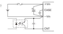
ex1)
CC-E
CE- 09XX
CE-
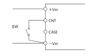
10XX
ex2)
CE- 3101
KS KWS KWD
12 Series Operation
PAE
All PAH-S48 SERIES modules allow series operation with any combination of output voltages. Please contact us for
PAF
maximum number of connections possible.
PAH
(1)Series Operation for High Output Voltage Applications
PAQ
When using PAH-S48 SERIES modules in a high output voltage configuration external bypassing diodes need to be connected to either module.
PF-A
a. Peak Reverse Voltage VRRM>2x the power module output voltage
PFE
b. Average Output Current Io>Twice the power module output current
PH
c. Forward Voltage VF = Minimum (Schottky Barrier Type, etc)
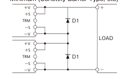
PMH
2)+/- Output Series Operation
When the load on the positive side is isolated from the load on the negative side, the following connection hookup is recommended. Bypass diodes are not needed when operate in this mode.
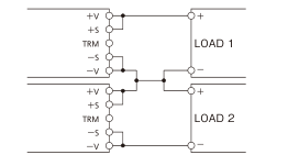
B-185
Page 44
PAH 50S48~200S48
13 Operation Temperature
The baseplate temperature range for PAH-S48 SERIES is from -40℃ to 100℃.
14 Operation Humidity
Avoid the buildup of condensation on or in the power mod- CC-E ule. CE- 09XX
15 Storage Temperature
CE- 10XX Please note that sudden temperature changes can cause condensation buildup, and other harmful affects to each CE- terminal solder. 3101
KS KWS KWD 16 Storage Humidity
High temperature and humidity can cause the terminals PAE on the module to oxidize. The quality of the solder will be- come worse. PAF
PAH 17 Cooling Method
The operating temperature is specified by the baseplate
PAQ temperature. Various cooling methods are possible such as
using heatsink or chassis of the equipment. If the temperature is very high, fan is recommended. PF-A
18 Parallel Operation
PFE
PAH series are not available for parallel operation. PH
19 Baseplate Temperature vs. Output Regulation
PMH This is the output voltage change ratio when varying the baseplate operation temperature.
20 Withstand Voltage
The power module is designed to withstand 1.5kVAC be- tween the input to the baseplate and input to output for 1 minute. In the case that the withstanding voltage is tested in the incoming goods test, etc., please set the limit of the test equipment to 20mA. The applied voltage must be increased gradually from zero to the testing value, and then decreased gradually at shutdown. Do not use a timer
mance.
where a pulse of several times the applied voltage can be generated. This could cause damage to the module. Be sure to short all the input and output pins as shown below.
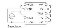
Voltage Tester
Input - Baseplate 1.5kVAC 1 min. (20mA)
B-186
Note : Please be sure to short all the input & output pins as shown above.
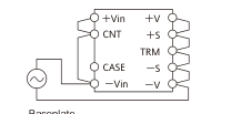
Baseplate Voltage Tester
Input - Output 1.5kVAC
1 min.(20mA)
Note : Please be sure CASE is not shorted to any pins.
21 Isolation Resistance
The isolation resistance is more than 100MΩ at 500VDC when tested with a DC isolation tester between the output and the baseplate. Make sure that during testing, the isolation testers do not produce a high pulse when the applied voltage is varied. Ensure that the tester is fully discharged after the test.
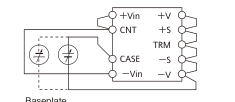
Voltage Tester
22 Vibration
Please refer to the power module mounting in the PAH-S48 series handbook in order to achieve vibration level stated in the specification.
23 Shock
Value for the conditions of our shipping and packaging.
24 Others
The performance of a system with Power Module is influ- enced according to various conditions -- PCBs, chassis, mechanics, heat dissipation. Please evaluate actual products, and confirm its perfor-
Please refer to "Power Module Application Note" for thermal design and mounting direction.
Page 45
PAH 50S48~200S48
3. Mounting Direction
1 Circuit Board Mounting
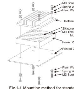
Spring Washer
Sikicone grease
Mounting Hole
Power Module
Printed Circuit Board
Spring Washer
Fig.1-1 Mounting method for standard model
(1) The power module is fixed to printed circuit board by 4 positions through the M3 tapped holes in the resin case side. Recommended torque is 5.5kgcm. (2) The M3 mounting tapped holes of the power module are connected to the baseplate. FG (Frame Ground) can be taken by these tapped holes. (3) Mounting Holes on Printed Circuit Board Input/Signal/Output Terminal Pin (φ1.0mm) Hole Diameter : φ1.5 mm Land Diameter : φ3.5 mm Output terminal Pin (φ2.0 mm ) Hole Diameter : φ2.5 mm Land Diameter : φ5.0 mm M3 Mounting Tap (FG) Hole Diameter : φ3.5 mm Land Diameter : φ7.0 mm
(4)Recommended Printed Circuit Board is a double sided glass epoxy (t=1.6mm) with through holes. (5) The standard power module lead length is 5.08mm.
2 Recommended Soldering Condition
Recommended soldering temperature is as follows. (1) Soldering dip :
260℃ within 10 seconds
Pre-heat condition : 110℃ 30~40 seconds (2) Soldering iron :
350℃ within 3 seconds
3 Recommended Cleaning Condition
Recommended cleaning condition after soldering is as follows.
- Cleaning solvent :
IPA (isopropyl alcohol)
- Cleaning Procedure : Use brush and dry the solvent
completely
Note : For other cleaning methods, contact us.
4 Heatsink Installation
1) The power module is fixed to the heatsink by 4 position through the M3 mounting tapped holes provided on the baseplate. It is recommended that the sequence to
CC-E
screw the 4 screws is in a diagonally manner and the recommended torque is 5.5kgcm.
CE-
2) Recommended hole diameter for heatsink = 3.5mm.
09XX
3) Use thermal grease or thermal sheet in between heat-
CE-
sink and baseplate to minimize the contact thermal
10XX
resistance. However, make sure that the thermal grease
CE-
or sheet is evenly applied and using no-warped heatsink
3101
in order to avoid any warpage on the baseplate.
KS
4) Recommended thermal sheet is as shown below. Cut-
KWS
ting the corner of thermal sheet is NOT advisable.
KWD
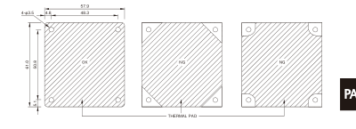
PAE
PAF
PAH
5 Output Derating
PAQ
(i) PAH50S48, PAH75S48, PAH100S48 & PAH150S48
PF-A
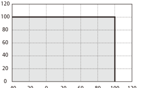
PFE
PH
PMH
-40 -20 0 20 60 80 100 120 Baseplate Temperature(℃)
(ii) PAH200S48
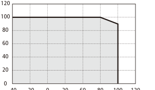
-40 -20 0 20 60 80 100 120 Baseplate Temperature(℃)
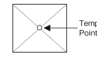
Temperature Measuring
Point of Baseplate
B-187
Page 46
PAH 50S48~200S48
6 External Fuse Rating
Fuse rating : PAH200S48 --- 250V 15A (Fast Blow Type)
PAH150S48 --- 250V 10A (Fast Blow Type) PAH100S48 --- 250V 7A (Fast Blow Type) PAH75S48 --- 250V 5A (Fast Blow Type) PAH50S48 --- 250V 5A (Fast Blow Type)
CC-E
CE- 09XX
CE- 10XX
CE- 3101
KS KWS KWD
PAE
PAF
PAH
PAQ
PF-A
PFE
PH
PMH
B-188
7 Notes
Over Current Protection operates > 105% of maximum DC output current.
Page 47
PAH300S48, 350S48
PAH 00 50S48 S
S nst ction an a
- PAH300S24, 350S24 Instruction Manual
B-175Page
- PAH50S48 ~200S48 Instruction Manual
B-182Page
B-196Page
- PAH450S48 Instruction Manual
B-204Page
- PAH75D Instruction Manual
- PAH200H Instruction Manual
B-216Page
Before using this product
Be sure to take note of precautions and warnings indicated in this manual when using this product. Improper usage may lead to electric shock or fire. Be sure to read this instruction manual thoroughly before using this product.
Precautions
- Avoid touching the baseplate and the case of this product be- cause they get hot.
- There are high voltage and high temperature components within this product. Refrain from disassembling this product or touching its internal components as this may lead to electric shock or burn.
- To avoid unexpected accident from placing hands or face near the unit during operation.
- Verify that connection to input, output and signal terminals are correct as indicated in this instruction manual.
- For acquisition of various Safety Standards and safety im- provement, be sure to use an external fuse.
- This product is designed for installation on electronic equip- ment.
- For input terminals of 48V input models, apply a voltage from a primary source with reinforced or double insulation.
- Output voltage of this product is considered to have hazard- ous energy level (voltage of 2V and above with power of 240W and above) and must not have physical contact with operator. Protection must be provided on this module when in- stalled on equipment to prevent physical contact with service technician himself or accidentally dropped tools during repair. Before repair, be sure to turn off the input source and confirm that input and output voltage have drop down to a safe level.
- Application circuit or component values described in this instruction manual are for reference only. When designing cir- cuit, be sure to verify actual circuit operation before determin- ing final application circuit or component values.
- Contents of this instruction manual are subject to change
PAH
without notice. When using this product, please refer to latest data sheet to satisfy this product specification.
- No part of this document may be copied or reproduced in any for, or by any mean without prior written consent of Densei- Lambda.
Note : CE Marking
CE Marking, when applied to a product covered by instruction manual, indicates compliance with the low voltage directive which complies with EN60950.
1. Terminal Explanation
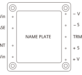
[Input Side Terminals] -Vin: -Input Terminal CASE: Baseplate Terminal
Vin
CNT: ON/OFF Control Terminal +Vin: +Input Terminal
CASE
[Output Side Terminals] -V: -Output Terminal
CNT
-S: -Remote Sensing Terminal TRM: Output Voltage Trimming Terminal
Vin
+S: +Remote Sensing Terminal +V: +Output Terminal
Baseplate can be connected to FG (frame ground) M3 threaded holes (standard model). Connect +Vin, -Vin, +V, -V with consideration of contacting resistance.
B-189
Page 48
PAH300S48, 350S48
2. Explanations on Specifications
1 Input Voltage Range
Input voltage range for PAH300, 350S48 Series is indicated below.
Input Voltage Range: 36 - 76VDC
Basically,ripple voltage (Vrpl) which results from rectifica- tion and filtering of commercial AC line is included within the input voltage as shown in Fig. 1-1. Ripple voltage must be limited within the voltage described below.
Allowable input ripple voltage: 4Vp-p
When this value is exceeded, the output ripple voltage be- comes large. Note that sudden input voltage change may cause variation of output voltage transitionally. Also, input voltage waveform peak value must not exceed above input voltage range.
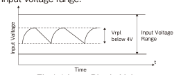
PAH
Fig.1-1 Input Ripple Voltage
- Basic Connection
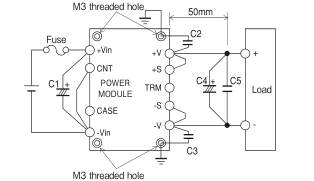
Fig.1-2 Basic Connection
Input Fuse This power module has no built-in fuse. Use external fuse to acquire various Safety Standards and to improve safety. Also, use fast-blow type for every module. Furthermore, fuse must be connected to the +Vin side if ‒Vin side is used as ground, or fuse must be connected to ‒Vin side if +Vin side is used as a ground.
Input Fuse recommended current rating:
PAH300S48: 15A (F15AH, 125/250V) PAH350S48: 20A (F20AH, 125/250V)
C1: 33μF To prevent the effect of input line inductance to the power module, connect electrolytic capacitor or ceramic capacitor between +Vin and ‒Vin terminals. Furthermore, use electrolytic capacitor with small ESR value. Especially take note that during line turn off at low ambient temperature, power module output will not normally shut down due to unstable C1 voltage. Also, ripple current flows across this capacitor. Therefore, B-190
verify maximum allowable ripple current this capacitor when selecting component. Verify actual ripple current value by actual measurement.
Recommended capacitor value: 33μF and above (Voltage Rating 100V and above)
Notes)1. Use low impedance electrolytic capacitor with excellent temperature characteristics. (Nippon Chemi-con LXV Series or equivalent) 2. When input line inductance becomes excessively high due to insertion of choke coil, operation of the power module could become unstable. For this case, increase C1 value more than the value indicated above. 3. When ambient temperature becomes lower than ‒20℃, connect two capacitors indicated above in parallel to reduce ESR.
C2, C3: 0.022μF To reduce spike noise voltage at the output, connect film capacitors or ceramic capacitors between +V and the nearest M3 threaded hole and between ‒V and the nearest M3 threaded hole. Also, take note that output spike noise voltage could vary according to PCB (printed circuit board) wiring design. However, for cases where baseplate is connected to +V or ‒V, use the nearest M3 threaded hole. (M3 threaded holes is internally connected to baseplate inside the Power Module.) For this type of connection, C2 and C3 can be omitted.
C4: For stable operation, connect an electrolytic capacitor be- tween +V and ‒V at 50mm distance from the output terminals. Take note that output ripple and output shutdown could be affected by electrolytic capacitor, equivalent impedance and inductance characteristics of wiring. Take note that output ripple voltage could vary according to PCB wiring design. For cases of abrupt changes in load current or input voltage, increasing capacitance value of the external capacitors could reduce the voltage fluctuation.
| Vout | C4 |
| 12V | 25V 470μF |
| 28V | 50V 220μF |
Table1-1 C4 Recommended Values of External Output Capacitor
Notes)1. Use low impedance electrolytic capacitor with excellent temperature characteristics. (Nippon Chemi-con LXY Series or equivalent) 2. Use three capacitors indicated above in parallel when ambient temperature becomes lower than ‒20℃ to reduce ESR. 3. Take note of the allowable ripple current of the ca- pacitor to be used. Especially, when load adding ca- pacitors for abrupt current changes, be sure to verify that ripple current does not exceed allowable ripple current before use.
Page 49
PAH300S48, 350S48
C5: 0.1μF To reduce spike noise voltage at the output, connect a ce- ramic capacitor between +V and ‒V within 50mm distance from the output terminals. Also, take note that output spike noise voltage could vary according to PCB wiring design. C6: When switches or connectors are used between input source and PAH300, 350S48 Series input terminals, im- pulse surge voltage is generated due to input throw-in by switch on/off or due to inserting/removing of power module from the active line. For this case, connect an additional electrolytic capacitor C6 as shown in fig.1-3 and fig. 1-4.
Recommended Capacitance Value: 33μF and above (Voltage Rating 100V and above)
Also, in-rush current flows at line throw-in. Therefore, be sure to verify capability of switch or fuse to withstand I2t at line throw-in.
Switch Fuse
| Switch Fuse + + C6 C1 | +Vin -Vin |
Fig.1-3 Input Filter with Input Switch
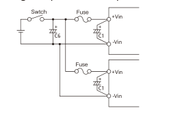
Fig.1-4 Input Filter when Plural Power Modules
Reverse input connection Reverse input polarity would cause module damage. For cases where reverse connections are possible, connect a protective diode and fuse. Use protective diode with higher voltage rating than the input voltage, and with higher surge current rating than the fuse.
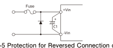
- Recommended input filter as EMI countermeasure (conforms to VCCI Class 1, FCC class A)
(1)Recommended input filter as EMI countermeasure (1)
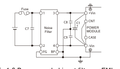
Fig.1-6 Recommended input filter as EMI countermeasure (1)
Recommended Values: C1: 470μF (Electrolytic Capacitor) 3 pcs in parallel C7: 4.7μF (Ceramic Capacitor) C8, C9: PAH300S48: 0.22μF (Film Capacitor) PAH350S48: 0.33μF (Film Capacitor) Noise filter: PAN4820 (DENSEI-LAMBDA)
(2)Recommended input filter as EMI countermeasure (2)
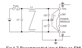
Fig.1-7 Recommended input filter as EMI countermeasure (2)
Recommended Values: C1: 470μF (electrolytic capacitor) 3 pcs in parallel C7: 4.7μF (ceramic capacitor) 2 pcs in parallel
PAH
C8, C9: PAH300S48 : 0.22μF (Film Capacitor) PAH350S48 : 0.33μF (Film Capacitor) L1: 150μH (common-mode choke coil)
Notes)1. For the power module output, connect output capacitors described in the basic circuit connection. 2. C1 (electrolytic capacitor) value can be reduced if im- pedance of input line is lower and operation of power module is stable. 3. VCCI Class 1, FCC Class A limits can be satisfied with the above recommended filter at Densei-Lambda measuring conditions. However, there are cases where above limits might not be satisfied due to in- put and output wiring method, as well as, peripheral circuits. When selecting input filter, be sure to verify actual EMI characteristics (CE and RE) before finalizing the filter. Refer to PAH300, 350S48-* Evaluation Data for details.
2 Output Voltage Adjustment Range
Output voltage could be adjusted within the range de- scribed below by external resister or variable resistor. However, take note that OVP might trigger when output voltage adjustment exceeds the ranges indicated below.
Output Voltage Adjustment Range 12V: -40% to +10% of nominal output Voltage 28V: -40% to +18% of nominal output Voltage
When increasing the output voltage, reduce the output current accordingly so as not to exceed the maximum output power. Take note that input voltage range is limited as shown in fig.2-1 when output voltage is increased. Remote sensing is possible even when output voltage is varied. For details on remote sensing function, please refer to “9. Remote Sensing”.
B-191
Page 50
PAH300S48, 350S48
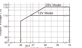
Input Voltage (VDC) Fig.2-1 Limit of Input Voltage
- Output Voltage Adjustment by external resistor or by variable resistor
(1)In case of adjusting output voltage lower (1-1) Available maximum output current = rated output current (1-2) Connect an external resistor Radj (down) be- tween the TRM terminal and ‒S terminal.
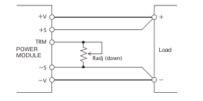
PAH
Fig.2-2 Connection for output voltage trim down
(1-3)Equation of external resistor and output voltage
100% -2〔kΩ〕
Radj(down)=
Δ%
Radj(down) : Value of external resistor Δ(%): Output voltage change rate against
nominal output voltage Below graph is relation Δ(%) and value of external resistor.
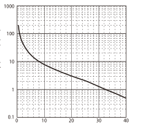
Change in Output VoltageΔ (%) Fig.2-3 Δ(%) vs. Radj (down) (1)
(2)In case of adjusting output voltage higher (2-1) Allowable maximum output current = maximum output power ÷ output voltage (reduce maximum output current in specification.)
(2-2) Connect an external resistor Radj (up) between TRM terminal and +S terminal.
B-192
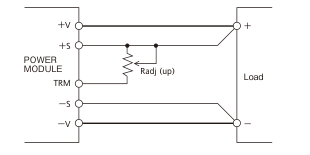
Fig.2-4 Connection for output voltage trim up
(2-3)Equation of external resistor and output voltage
Vo(100%+Δ%) 100%+2×Δ%
-
Radj(up)=
〔kΩ〕
1.225×Δ%
Δ%
Vo: nominal output value of module Radj (up): external adjustment resistor Δ(%): Output voltage change rate against nominal output voltage Below graph is relationΔ(%) and value of external resistor.
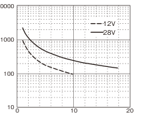
Change in Output VoltageΔ (%)
Fig.2-5 Δ% vs. Radj (up) (2)
3 Maximum Ripple and Noise
Measured value according to the specified methods based on JEITA-9141 (Clause 7.12 and clause 7.13) which is de- scribed in the following. Connect according to fig.3-1 and measure. Connect capacitors (C2, C3: film capacitor or ceramic capacitor 0.022μF) between output terminals and the nearest M3 threaded hole. Connect capacitors (C4: refer to table 1-1 for electrolytic capacitor values, C5: ceramic capacitor 0.1μF) at 50mm distance from the output terminals. Measure at ceramic capacitor(C5) terminals as shown in fig. 3-1 using coaxial cable with JEITA attachment. Use oscilloscope with 100MHz frequency bandwidth or equivalent. Take note that output ripple voltage and output spike noise
may vary depending on PCB wiring design. Generally, increasing capacitance value of external ca- pacitor can reduce output ripple voltage and output spike noise.
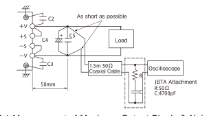
Fig.3-1 Measurement of Maximum Output Ripple & Noise
Page 51
PAH300S48, 350S48
4 Maximum Line Regulation
Maximum value of output voltage change when input voltage is gradually varied (steady state) within specified input voltage range.
5 Maximum Load Regulation
Maximum value of output voltage change when output current is gradually varied (steady state) within specified output current range. When using at dynamic load mode, audible noise could be heard from the power module and output voltage fluctuation might increase. A thorough pre-evaluation must be performed before using this power module.
6 Over Current Protection (OCP)
This power module has built-in OCP function. Output will recover when short circuit or overload conditions are released. OCP setting value is fixed and therefore, cannot be externally adjusted. Also, take note that power module might be damaged continuing output short circuit or over load conditions depending on thermal conditions.
7 Over Voltage Protection (OVP)
This power module has built-in OVP function. OVP set point is relative to the rated output voltage value. OVP setting value is fixed and therefore, cannot be externally adjusted. When OVP is triggered, output can be recovered by turning input line off and then turning it on again after lowering the input voltage below the voltage value indicated below, or by manual reset of the ON/OFF control terminal. Reset time for ON/OFF control terminal is 100ms or longer.
OVP release input voltage value : 24VDC and below When verifying OVP function by applying external voltage at the output terminals, applied voltage value should not exceed specified OVP maximum value. Refer to specifica- tion table for OVP maximum value. Avoid applying external voltage that exceeds OVP maximum value because this will cause power module damage.
8 Over Temperature Protection (OTP)
This power module has built-in OTP function. This function operates and shuts down the output when ambient temperature or internal temperature of power module abnormally rises. OTP operates at 105℃ to 130℃ baseplate temperature. OTP can be released when baseplate temperature drops down approximately to within 80℃ to 95℃. However, take note that OTP will operate again unless the cause of abnormal heat of the power module is eliminated.
9 Remote Sensing (+S, -S terminal)
Remote sensing terminal is provided to compensate for voltage drop across the wirings from the power module output terminal to the load input terminal. When remote sensing function is not used (local sensing), short +S terminal to +V terminal and, ‒S terminal to ‒V terminal. Take note that voltage compensation range for line drop (voltage drop due to wiring) is determined such that output voltage at the output terminals is within output voltage range and that voltage between ‒V and ‒S terminals
is within 2V or less. Even for remote sensing case, use power module such that output power is within specified maximum output power. Furthermore, reduce noise effect by using shield wire, twist pair, or parallel pattern.
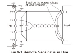
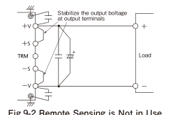
PAH
10 ON/OFF Control (CNT terminal)
Without turning the input supply on and off, the output can be enabled and disabled using this function. This function also can be used for output sequence of plural power modules. There are two kinds of logic control, negative logic control and positive logic control, depend on the option selected. ON/OFF control circuit is on the primary side (the input side). For secondary control, isolation can be achieved through the use of an opto-coupler or relay.
| Logic | CNT Terminal Level to -Vin Terminal | Output status | |
|---|---|---|---|
| Standard /Toption | Negative Logic | H Level (4V≦H≦35V) or Open | OFF |
| L Level (0V≦L≦0.8V) or Short | ON | ||
| /Poption /PToption | Positive Logic | H Level (4V≦H≦35V) or Open | ON |
| L Level (0V≦L≦0.8V) or Short | OFF |
Notes)1. When ON/OFF control function is not used for the Standard and /T option, CNT terminal should be shorted to ‒Vin terminal. 2. When ON/OFF control function is not used for the /P option and /PT option, CNT terminal should be opened. 3. When using long wiring, for prevention of noise, at- tach a 0.1µF capacitor between CNT terminal and ‒ Vin terminal. 4. At L level, maximum source current from CNT terminal to ‒Vin terminal is 0.5mA 5. The maximum CNT terminal voltage is 35V. (1)Output ON/OFF control
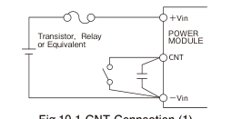
Fig.10-1 CNT Connection (1)
B-193
Page 52
PAH300S48, 350S48
(2)Secondary (output side) control
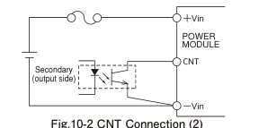
11 Parallel Operation
Parallel Operation can not be used.
12 Series Operation
Series operation is possible for PAH300, 350S48 series. Connections shown fig. 12-1 and fig. 12-2 are possible.
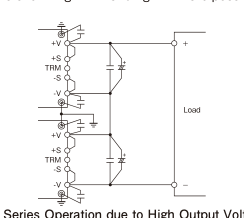
PAH
Fig.12-1 Series Operation due to High Output Voltage
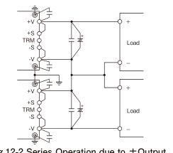
Fig.12-2 Series Operation due to ±Output
13 Operating ambient temperature
There is no restriction on mounting direction but there should be enough consideration for airflow so that heat does not accumulate around the power module vicinity. Determine external components configuration and mounting direction on PCB such that air could flow through the heatsink at forced cooling and conventional cooling. By maintaining actual baseplate temperature below 100℃, operation is possible. For details on thermal design, refer to Application Notes “Thermal Design”. Note : Maximum baseplate temperature is 100℃. For worst case operating condition, verify baseplate temperature at measurement point indicated in fig. 13-1.
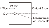
Input Side
Measurement Point of Baseplate Temperature
Fig.13-1 Measurement Point of Baseplate Temperature
B-194
For better improvement of power module reliability, de- rating of baseplate temperature when using is recommended.
14 Operating Ambient Humidity
Take note that moisture could lead to power module ab- normal operation or damage.
15 Storage Ambient Temperature
Abrupt temperature change would cause moisture formation that leads to poor solderability of each terminal of the power module.
16 Storage Ambient Humidity
Take enough care when storing the power module be- cause rust which causes poor solderability would form in each terminal when stored in high temperature, high hu- midity environment.
17 Cooling Method
Operating temperature range is specified by the baseplate temperature. Therefore, several methods of heat dissipation are possible. For details on thermal design, refer to Application Notes “Thermal Design”.
18 Baseplate Temperature vs. Output Voltage Drift
Output voltage drift is defined as the rate of voltage change when baseplate temperature only is changed during operation.
19 Withstand Voltage
This power module is designed to have a withstand voltage of 1.5kVDC between input and baseplate, 1.5kVDC between input and output and 500VDC between output and baseplate for 1 minute. When conducting withstand voltage test during incoming inspection, be sure to apply DC voltage. Also, set the current limit value of the withstand voltage testing equipment to 10mA. Be sure to avoid conducting test with AC voltage because this would cause power module damage. Furthermore, avoid throw in or shut off of the testing equipment when applying or when shutting down the test voltage. Instead, gradually increase or decrease the applied voltage. Take note especially not to use the timer of the
test equipment because when the timer switches the ap- plied voltage off, impulse voltage which has several times the magnitude of the applied voltage is generated causing damage to the power module. Connect the terminals as shown in the diagram below.
Page 53
PAH300S48, 350S48
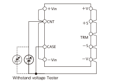
1.5kVDC 1 minute (10mA) Fig.19-1 Withstand Voltage Test for Input-Output and Input - Baseplate
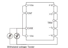
500VDC 1minute (10mA)
Fig.19-2 Withstand Voltage Test for Output-Baseplate
20 Isolation Resistance
Use DC isolation tester (MAX 500V) between output and baseplate. Isolation resistance value is 100MΩ and above
at 500VDC applied voltage. Also take note that depending on the isolation tester used, some testers generate high voltage pulse. Discharge the power module after test using a resistor, etc.
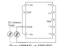
Over 100MΩ at 500VDC Fig.20-1 Isolation Test
21 Vibration
Vibration of power module is defined in case of mounting on printed circuit board.
22 Shock
Withstand shock value is defined to be the value at Densei -Lambda shipment and packaging conditions.
PAH
23 Others
Please refer to "Power Module Application Note" for thermal design and mounting direction.
3. Before concluding power module damage
Verify following items before concluding power module damage. 1)No output voltage
- Is specified input voltage applied?
- Are the ON/OFF control terminal (CNT), remote sensing terminal (+S, -S), output voltage trimming terminal (TRM) correctly connected?
- For cases where output voltage adjustment is used, is the resistor or variable resistor setting, connections cor- rectly done?
- Are there no abnormalities in the output load used?
- Is the baseplate temperature within the specified tem- perature range?
2)Output voltage is high
- Are the remote sensing terminals (+S, -S) correctly con- nected?
- Is the measurement done at the sensing points?
- For cases where output voltage adjustment is used, is the resistor or volume setting, connections correctly done?
3)Output voltage is low
- Is specified input voltage applied?
- Are the remote sensing terminals (+S, -S) correctly con- nected?
- Is the measurement done at the sensing points?
- For cases where output voltage adjustment is used, is the resistor or variable resistor setting, connections cor- rectly done?
- Are there no abnormalities in the output load used?
4)Load regulation and line regulation is large
- Is specified input voltage applied?
- Are the input terminals and the output terminals firmly connected?
- Is the measurement done at the sensing points?
- Is the input or output wire too thin?
5)Output ripple voltage is large
- Is the measuring method used the same or equivalent with the specified method in the Application Notes?
- Is the input ripple voltage value within the specified value?
B-195
Page 54
PAH 450S48
PAH450S48 nst
ction an a
- PAH300S24, 350S24 Instruction Manual
B-175Page
- PAH50S48 ~200S48 Instruction Manual
B-182Page
- PAH300S48, 350S48 Instruction Manual
B-189Page
B-204Page
- PAH75D Instruction Manual
- PAH200H Instruction Manual
B-216Page
BEFORE USING THE POWER SUPPLY UNIT
Be sure to read this instruction manual thoroughly before using this product. Pay attention to all cautions and warnings before using this product. Incorrect usage could lead to an electrical shock, damage to the unit or a fire hazard.
WARNING
- Do not make unauthorized changes to power supply unit, otherwise you may have electric shock and void your war- ranty.
- Do not touch this unit and the internal components in opera- tion or shortly after shut down. They may have high voltage
PAH or high temperature and as the unit dissipates its heat so the surface of the unit is hot. You may receive electric shock or burn.
- When the unit is operating, keep your hands and face away from it; you may be injured by an accident.
- Do not use unit under unusual condition such as emission of smoke or abnormal smell and sound etc. It might cause fire and electric shock. In such case, please contact us; do not repair by yourself, as it is dangerous for the user.
- Do not drop or insert anything into unit. It might cause failure and fire.
- Do not operate these units under condensation condition. It may cause fire and electric shock.
CAUTION
- As a component part, compliance with the standard will be based upon installation in the final application. This product must be installed in a restricted access location, accessible to authorized competent personnel only. These DC to DC converters have basic insulation between the input and the output. All models with an output 48V and above are con- sidered to be non-SELV and must not be accessible to the operator. The installer must also provide protection against inadvertent contact by a service engineer.
- The input to this power supply must be isolated from the mains input by reinforced insulation.
- The equipment has been evaluated for use in a Pollution De- gree 2 environment.
- This power supply is primarily designed and manufactured to be used and enclosed in other equipment.
- Confirm connections to input/output terminals and signal ter- minals are correct as indicated in the instruction manual.
- Attach a HBC external fuse to each module to ensure safety operation and compliance to each safety standard approval. The recommended input fuse rating within the instructions is as follows: 30A, 250V fast acting fuse. The breaking capac- ity and voltage rating of this fuse may be subject to the end use application.
B-196
- Input voltage, Output current, Output power, ambient tem- perature and ambient humidity should be used within specifi- cations, otherwise the unit will be damaged.
- For application equipment, which requires very high reliability (Nuclear related equipment, traffic control equipment, medi- cal equipment, etc.), please provide fail safety function in the equipment.
- Do not use the product in environment with strong electro- magnetic field, corrosive gas and conductive substance.
- Do not operate and store this unit at an environment where condensation occurs. In such case, waterproof treatment is necessary.
- Never operate the unit under over current or shorted condi- tions for 30 seconds or more and out of Input Voltage Range as specification. Insulation failure, smoking, burning or other damage may occur to the unit.
- The output voltage of this power supply unit is considered to be a hazardous energy level (The voltage is 2V or more and the electric power is 240VA or more). Prevention from direct contact with output terminal is highly necessary. While installing or servicing this power supply unit, avoid dropping tools by mistake or direct contact with output terminal. This might cause an electrical shock. While repairing this power supply unit, the DC input power must be switched off and the input and output voltage should be safe level.
- To maintain the SELV output for outputs 28V and below, un- der fault conditions, the output must be connected to earth in the final application. However, during installation please ensure both the input positive and output positive are not grounded.
- The application circuits and their parameter are for reference only. Be sure to verify effectiveness of application circuits and their parameters before finalizing circuit design.
- Do not inject abnormal voltage to output terminal and signal terminal from the outside. The injection of reverse voltage or over voltage exceeding nominal output voltage to output ter- minals might cause damage to internal components.
- This information in this document is subject to change with- out prior notice. For actual design-in, please refer to the lat- est publications of data sheet, etc., for the most up-to date specifications of the unit.
- No part of this document may be copied or reproduced in any form without prior written consent of Densei-Lambda.
Note : CE MARKING
CE Marking when applied to a product covered by this handbook indicates compliance with the low voltage directive (2006/95/ EC) in that it complies with EN60950.
Page 55
PAH 450S48
1. Terminal Explanation
1 Terminal Arrangement
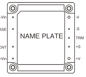
CASE
[Input Side Terminals] -Vin :-Input Terminal CASE :Baseplate Terminal CNT :ON/OFF Control Terminal +Vin :+Input Terminal
[Output Side Terminals] -V :-Output Terminal -S :-Remote Sensing Terminal TRM :Output Voltage Trimming Terminal +S :+Remote Sensing Terminal +V :+Output Terminal
PAH
Baseplate can be connected to FG (frame ground) M3 threaded holes. (standard model) Connect +Vin, -Vin, +V, -V with consideration of contacting resistance.
2. Explanations on Specifications
1 Input Voltage Range
Input voltage range for PAH450S48 Series is indicated below.
Input Voltage Range : 36 - 76VDC
Basically,ripple voltage (Vrpl) which results from rectifica- tion and filtering of commercial AC line is included within the input voltage as shown in Fig. 1-1. Ripple voltage must be limited within the voltage described below.
Allowable input ripple voltage : 4Vp-p
When this value is exceeded, the output ripple voltage be- comes large. Note that sudden input voltage change may cause variation of output voltage transitionally. Also, input voltage waveform peak value must not exceed above input voltage range.
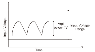
Fig.1-1 Input Ripple Voltage
- Basic Connection
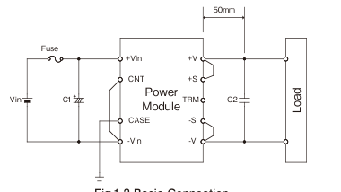
Fig.1-2 Basic Connection
Input Fuse This power module has no built-in fuse. Use external fuse to acquire various Safety Standards and to improve safety. Also, use fast-blow type for every module. Furthermore, fuse must be connected to the +Vin side if -Vin side is used as ground, or fuse must be connected to -Vin side if +Vin side is used as a ground.
Input Fuse recommended current rating:
PAH450S48 : 30A
B-197
Page 56
PAH 450S48
C1 : 100μF To prevent the effect of input line inductance to the power module, connect electrolytic capacitor or ceramic capacitor between +Vin and -Vin terminals. Furthermore, use electrolytic capacitor with small ESR value. Especially take note that during line turn off at low ambient temperature, power module output will not normally shut down due to unstable C1 voltage. Also, ripple current flows across this capacitor. Therefore, verify maximum allowable ripple current this capacitor when selecting component. Verify actual ripple current value by actual measurement.
Recommended capacitor value : 100μF and above (Voltage Rating 100V and above)
Notes 1. Use low impedance electrolytic capacitor with excellent temperature characteristics. (Nippon Chemi-con LXV Series or equivalent) 2. When input line inductance becomes excessively high due to insertion of choke coil, operation of the power module could become unstable. For this case, increase C1 value more than the value indicated above.
PAH C2 : For stable operation, connect a ceramic capacitor be- tween +V and -V within 50mm distance from the output terminals. Take note that output ripple and output shutdown could be affected by ceramic capacitor, equivalent impedance and inductance characteristics of wiring. Take note that output ripple voltage could vary according to PCB wiring design. For cases of abrupt changes in load current or input voltage, increasing capacitance value of the external capacitors could reduce the voltage fluctuation.
| Vout | C2 |
| 28V | 50V 22μF×4parallel |
| 48V | 100V 4.7μF×6parallel |
Table1-1 C4 Recommended Values of External Output Capacitor
Maximum capacitance (electrolytic capacitor) that can be connected between +V and -V, is shown below. Maximum capacitance of output capacitor
28V : 10,000μF 48V : 2,000μF
Notes Take note of the allowable ripple current of the capacitor to be used. Especially, when load adding capacitors for abrupt current changes, be sure to verify that ripple current does not exceed allowable ripple current before use.
C3: When switches or connectors are used between input source and PAH450S48 Series input terminals, impulse surge voltage is generated due to input throw-in by switch on/off or due to inserting/ removing of power module from the active line. For this case, connect an additional electrolytic capacitor C3 as shown in fig.1-3 and fig. 1-4.
Recommended Capacitance Value : 100μF and above (Voltage Rating 100V and above)
B-198
Also, in-rush current flows at line throw-in. Therefore, be sure to verify capability of switch or fuse to withstand I2t at line throw-in.
Switch
Fuse
| Fuse C3 C1 | +Vin -Vin |
Fig.1-3 Input Filter with Input Switch
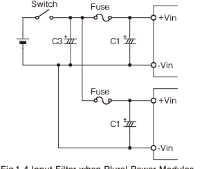
Fig.1-4 Input Filter when Plural Power Modules
Reverse input connection Reverse input polarity would cause module damage. For cases where reverse connections are possible, connect a protective diode and fuse. Use protective diode with higher voltage rating than the input voltage, and with higher surge current rating than the fuse.
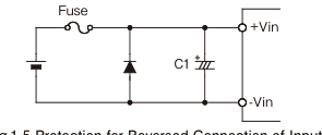
Fig.1-5 Protection for Reversed Connection of Input
- Recommended application as EMI countermeasure (compliant to VCCI Class 1, FCC class A)
(1)Recommended application as EMI countermeasure
Power Module
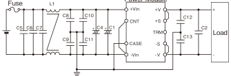
Fig.1-6 Recommended input filter as EMI countermeasure
Page 57
PAH 450S48
Recommended Values: C1: 220μF (Electrolytic Capacitor) C2: Apply C2 capacitance in Basic Connection. C4: 220μF (Electrolytic Capacitor) C5-C7: 2.2μF (Ceramic Capacitor) C8,C9: 0.22μF (Film Capacitor) C10, C11: 4700pF (Film Capacitor) C12, C13: 0.47μF (Film Capacitor) L1 : 80μH (Common-mode choke coil)
Notes 1. C4 (Electrolytic Capacitor) can be deleted if impedance of input line is lower and operation of power module is stable. 2. C12 and C13 (Film Capacitor) can be deleted when output is connected to earth. 3. VCCI Class 1, FCC Class A limits can be satisfied with the above recommended filter at Densei-Lambda measuring conditions. However, there are cases where above limits might not be satisfied due to input and output wiring method, as well as, peripheral circuits. When selecting input filter, be sure to verify actual EMI characteristics (CE and RE) before finalizing the filter. Refer to PAH450S48-\* Evaluation Data for details.
2 Output Voltage Adjustment Range
Output voltage could be adjusted within the range de- scribed below by external resister or variable resistor. However, take note that OVP might trigger when output voltage adjustment exceeds the ranges indicated below.
Output Voltage Adjustment Range 28V: -40% - +18% of Nominal Output Voltage 48V: -40% - +20% of Nominal Output Voltage
When increasing the output voltage, reduce the output current accordingly so as not to exceed the maximum output power. Take note that input voltage range is limited as shown in fig.2-1 when output voltage is increased. Remote sensing is possible even when output voltage is varied. For details on remote sensing function, please refer to “9.Remote Sensing”
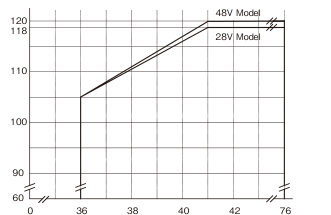
Input Voltage(VDC)
Fig.2-1 Limit of Input Voltage
- Output Voltage Adjustment by external resistor or by variable resistor (1) In case of adjusting output voltage lower (1-1) Available maximum output current = rated out- put current
(1-2) Connect an external resistor Radj(down) be- tween the TRM terminal and -S terminal.
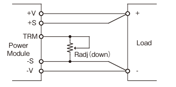
Fig.2-2 Connection for output voltage trim down
(1-3) Equation of external resistor and output voltage
100% 2 [ ]
Radj(down) =
kΩ Δ%
Radj(down) : Value of external resistor Δ(% )
: Output voltage change rate against nominal output voltage
Below graph is relationΔ(% ) and value of ex-
PAH
ternal resistor.
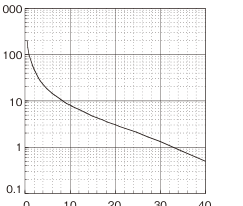
Change in Output Voltage Δ(%)
Fig.2-3 Δ(% ) vs. Radj(down) (1)
(2) In case of adjusting output voltage higher (2-1) Allowable maximum output current = maximum output power ÷ output voltage (reduce maximum output current in specification.)
(2-2) Connect an external resistor Radj(up) between TRM terminal and +S terminal.
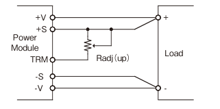
Fig.2-4 Connection for output voltage trim up
B-199
Page 58
PAH 450S48
(2-3) Equation of external resistor and output voltage
Radj(up)= Vo(100%+Δ%)
100%+2×Δ%
[ ] kΩ
1.225×Δ%
Δ%
Vo : nominal output value of module Radj(up) : external adjustment resistor Δ (% ) : Output voltage change rate against nominal output voltage
Below graph is relation Δ(% ) and value of ex- ternal resistor.
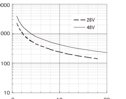
10000
0
10
20
Change in Output Voltage Δ(%)
PAH
Fig.2-5 Δ(% ) vs. Radj(up) (2)
3 Maximum Ripple and Noise
Measured value according to the specified methods based on JEITA-9141 (Clause 7.12 and clause 7.13) which is de- scribed in the following. Connect according to fig.3-1 and measure. Connect ca- pacitors (C2: refer to table 1-1 for ceramic capacitor values) at 50mm distance from the output terminals. Measure at ceramic capacitor (C2) terminals as shown in fig. 3-1 using coaxial cable with JEITA attachment. Use oscilloscope with 100MHz frequency bandwidth or equivalent. Take note that output ripple voltage and output spike noise may vary depending on PCB wiring design. Generally, increasing capacitance value of external ca- pacitor can reduce output ripple voltage and output spike
noise.
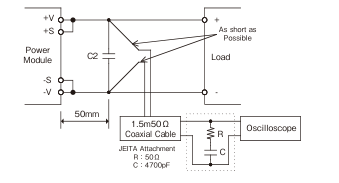
Fig.3-1 Measurement of Maximum Output Ripple & Noise
4 Maximum Line Regulation
Maximum value of output voltage change when input voltage is gradually varied (steady state) within specified in- putvoltage range.
B-200
5 Maximum Load Regulation
Maximum value of output voltage change when output current is gradually varied (steady state) within specified output current range. When using at dynamic load mode, audible noise could be heard from the power module and output voltage fluctuation might increase. A thorough pre-evaluation must be performed before using this power module.
6 Over Current Protection (OCP)
This power module has built-in OCP function. Output will recover when short circuit or overload conditions are released. OCP setting value is fixed and therefore, cannot be externally adjusted. Also, take note that power module might be damaged continuing output short circuit or over load conditions depending on thermal conditions.
7 Over Voltage Protection (OVP)
This power module has built-in OVP function. OVP set point is relative to the rated output voltage value. OVP setting value is fixed and therefore, cannot be externally adjusted. When OVP is triggered, output can be recovered by turning input line off and then turning it on again after lowering the input voltage below the voltage value indicated below, or by manual reset of the ON/OFF control terminal. Reset time for ON/OFF control terminal is 100ms or longer.
OVP release input voltage value : 10VDC and below
When verifying OVP function by applying external voltage at the output terminals, applied voltage value should not exceed specified OVP maximum value. Refer to specifica- tion table for OVP maximum value. Avoid applying external voltage that exceeds OVP maximum value because this will cause power module damage.
8 Over Temperature Protection (OTP)
This power module has built-in OTP function. This function operates and shuts down the output when am- bient temperature or internal temperature of power module abnormally rises. OTP operates at 105℃ to 130℃ baseplate temperature. OTP can be released when baseplate temperature drops down approximately to within 80℃ to 95℃. However, take note that OTP will operate again unless the cause of abnormal heat of the power module is eliminated.
9 Remote Sensing (+S, -S terminal)
Remote sensing terminal is provided to compensate for voltage drop across the wirings from the power module output terminal to the load input terminal. When remote sensing function is not used (local sensing), short +S terminal to +V terminal and, -S terminal to -V terminal. Take note that voltage compensation range for line drop (voltage drop due to wiring) is determined such that out-
Page 59
PAH 450S48
put voltage at the output terminals is within output voltage range and that voltage between -V and -S terminals is within 2V or less. Even for remote sensing case, use power module such that output power is within specified maximum output power. Furthermore, reduce noise effect by using shield wire, twist pair, or parallel pattern.
Stabilize the output voltage
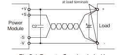
Fig.9-1 Remote Sensing is in Use
Stabilize the output voltage
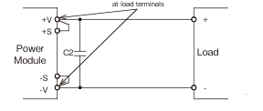
Fig.9-2 Remote Sensing is Not in Use
10 ON/OFF Control (CNT terminal)
Without turning the input supply on and off, the output can be enabled and disabled using this function. This function also can be used for output sequence of plural power modules. ON/OFF control circuit is on the primary side (the input side). For secondary control, isolation can be achieved through the use of an opto-coupler or relay.
Notes 1. When ON/OFF control function is not used for the Standard and /T option, CNT terminal should be shorted to -Vin terminal. 2. When using long wiring, for prevention of noise, attach a 0.1µF capacitor between CNT terminal and -Vin terminal. 3. At L level, maximum source current from CNT terminal to -Vin terminal is 0.5mA. 4. The maximum CNT terminal voltage is 35V.
(1) Output ON/OFF control
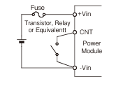
Fig.10-1 CNT Connection (1)
(2)Secondary (output side) control
| Fuse Secondary (output side) | +Vin CNT Power Module -Vin |
Fig.10-2 CNT Connection (2)
11 Parallel Operation
Parallel Operation can not be used.
12 Series Operation
Series operation is possible for PAH450S48 series. Connections shown fig. 12-1 and fig. 12-2 are possible.
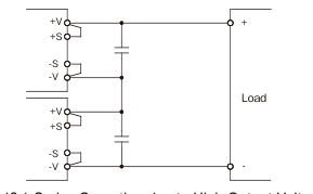
Fig.12-1 Series Operation due to High Output Voltage
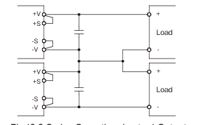
PAH
Fig.12-2 Series Operation due to ±Output
13 Operating ambient temperature
There is no restriction on mounting direction but there should be enough consideration for airflow so that heat does not accumulate around the power module vicinity. Determine external components configuration and mounting direction on PCB such that air could flow through the heatsink at forced cooling and conventional cooling. By maintaining actual baseplate temperature below 100℃, operation is possible. For details on thermal design, refer to Application Notes “Thermal Design”.
Note : Maximum baseplate temperature is 100℃. For worst case operating condition, verify baseplate temperature at measurement point indicated in fig. 13-1.
17mm
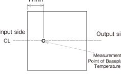
Fig.13-1 Measurement Point of Baseplate Temperature
For better improvement of power module reliability, derating of baseplate temperature when using is recommended.
B-201
Page 60
PAH 450S48
14 Operating Ambient Humidity
Take note that moisture could lead to power module ab- normal operation or damage.
15 Storage Ambient Temperature
Abrupt temperature change would cause moisture formation that leads to poor solderability of each terminal of the power module.
16 Storage Ambient Humidity
Take enough care when storing the power module be- cause rust which causes poor solderability would form in each terminal when stored in high temperature, high hu- midity environment.
17 Cooling Method
Operating temperature range is specified by the baseplate temperature. Therefore, several methods of heat dissipation are possible. PAH For details on thermal design, refer to Application Notes “Thermal Design”.
18 Baseplate Temperature vs. Output Voltage Drift
Output voltage drift is defined as the rate of voltage change when baseplate temperature only is changed during operation.
19 Withstand Voltage
This power module is designed to have a withstand voltage of 1.5kVDC between input and baseplate, 1.5kVDC between input and output and 500VDC between output and baseplate for 1 minute. When conducting withstand voltage test during incoming inspection, be sure to apply DC voltage. Also, set the current limit value of the withstand voltage testing equipment to 10mA. Be sure to avoid conducting test with AC voltage because this would cause power module damage. Furthermore, avoid throw in or shut off of the testing equipment when applying or when shutting down the test voltage. Instead, gradually increase or decrease the applied voltage. Take note especially not to use the timer of the
test equipment because when the timer switches the ap- plied voltage off, impulse voltage which has several times the magnitude of the applied voltage is generated causing damage to the power module. Connect the terminals as shown in the diagram below.
B-202
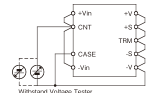
1.5kVDC 1 minute (10mA)
Fig.19-1 Withstand Voltage Test for Input-Output and Input - Baseplate
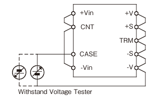
500VDC 1minute (10mA)
Fig.19-2 Withstand Voltage Test for Output-Baseplate
20 Isolation Resistance
Use DC isolation tester (MAX 500V) between output and baseplate. Isolation resistance value is 100MΩ and above at 500VDC applied voltage. Also take note that depending on the isolation tester used, some testers generate high voltage pulse. Discharge the power module after test using a resistor, etc.
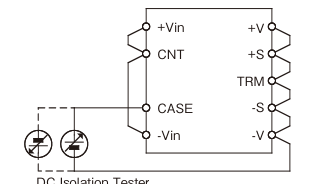
Over 100MΩ at 500VDC
Fig.20-1 Isolation Test
21 Vibration
Vibration of power module is defined in case of mounting on printed circuit board.
22 Shock
Withstand shock value is defined to be the value at Densei -Lambda shipment and packaging conditions.
23 Others
Please refer to "Power Module Application Note" for thermal design and mounting direction.
Page 61
PAH 450S48
3. Before concluding power module damage
Verify following items before concluding power module damage.
1)No output voltage
- Is specified input voltage applied?
- Are the ON/OFF control terminal (CNT), remote sensing terminal (+S, -S), output voltage trimming terminal (TRM) correctly connected?
- For cases where output voltage adjustment is used, is the resistor or variable resistor setting, connections correctly done?
- Are there no abnormalities in the output load used?
- Is the baseplate temperature within the specified temperature range?
2)Output voltage is high
- Are the remote sensing terminals (+S, -S) correctly connected?
- Is the measurement done at the sensing points?
- For cases where output voltage adjustment is used, is the resistor or volume setting, connections correctly done?
3)Output voltage is low
- Is specified input voltage applied?
- Are the remote sensing terminals (+S, -S) correctly connected?
- Is the measurement done at the sensing points?
- For cases where output voltage adjustment is used, is the resistor or variable resistor setting, connections correctly done?
- Are there no abnormalities in the output load used?
4)Load regulation and line regulation is large
- Is specified input voltage applied?
- Are the input terminals and the output terminals firmly connected?
- Is the measurement done at the sensing points?
- Is the input or output wire too thin?
5)Output ripple voltage is large
- Is the measuring method used the same or equivalent with the specified method in the Application Notes?
PAH
- Is the input ripple voltage value within the specified value?
B-203
Page 62
PAH75D24
PAH 5 4 S
S nst
ction an a
- PAH300S24, 350S24 Instruction Manual
B-175Page
- PAH50S48 ~200S48 Instruction Manual
B-182Page
- PAH300S48, 350S48 Instruction Manual
B-189Page
B-196Page
- PAH450S48 Instruction Manual
- PAH200H Instruction Manual
B-216Page
Before Using This Power Module
Pay attention to all warnings and cautions before using this unit. Incorrect usage could lead to an electric shock, damage to the unit, or a fire hazard. Be sure to read below warnings and cautions before using the power module.
Warning
- Do not touch heatsink and case which may be hot.
- Do not open the case and touch the internal components. They may have high temperature or high voltage which may get you in electric shock or burned.
- When the unit is operating, keep your hands and face away from the unit. You may get injured by accident.
PAH
Caution
- Confirm connections to input/output terminals and signal ter- minals are correct as indicated in the instruction manual.
- Attach a fast blow type external fuse to each module to en- sure safety operation and to acquire each safety standard ap- proval.
- This power module is designed for professional installation within an end user equipment.
- The input supply, 18 - 36VDC must be isolated from the mains
primary power supply by reinforced insulation in accordance with EN60950/UL1950.
- Equipment with these products mounted inside must be pro- tected to prevent contact with by technical service staff or dropped tools, etc. When repairing the equipment, please be sure to turn off input sourse, and confirm that input and output voltage has dropped down to a safe level.
- The application circuits and their parameter are for reference only. Be sure to verify effectiveness of application circuits and their parameters before finalizing circuit design.
- The information in this document is subject to change without notice. For actual design-in, please refer to the latest publica- tions of data sheet, etc., for the most up-to-date specifications of the unit.
- No part of this document may be copied or reproduced in any form or by any mean without prior written consent of Densei- Lambda.
- Do not inject abnormal voltage to output or signal pins. Espe- cially, when inject negative voltage or voltage exceeding rated output voltage to output pins might cause damage to internal output capacitor (Functional Polymerized Capacitor).
1. Terminal Pin Configurations
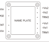
-Vin : Negative Input Terminal CASE : Baseplate Terminal CNT : ON/OFF Control Terminal +Vin : Positive Input Terminal +Vo2 : CH2 Positive Output Terminal -Vo2 : CH2 Negative Output Terminal TRM2 : CH2 Output Voltage Adjustment Terminal +Vo1 : CH1 Positive Output Terminal -Vo1 : CH1 Negative Output Terminal TRM1 : CH1 Output Voltage Adjustment Terminal
2. Explanation on Specifications
1 Basic Connection
Output voltage/input & load regulation Output regulation measurment point
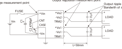
Output ripple & noise measurement point Bandwith of scope:20MHz
Note: This diagram is for Negative Logic “ON/OFF” Option.
B-204
Page 63
PAH75D24
2 External Components
The table below shows the recommended values for the above external components.
| Item | Vo1 | Vo2 |
| F1 | 250V 10A (UL approved and fast acting) | |
| C1 | For Tbp = -20°C to 100°C Select the E-cap with low ESR and sufficient allowable ripple current, verify actual ripple current value by actual measurement. Recommended Nichicon UPW series, Capaci- tance value: 100µF and above. Voltage rating: 50V and above. For Tbp = -40°C to 100°C Recommended ceramic cap.: 50V 33uF | |
| C2 | Ceramic capacitor : 2kVAC 4700pF | |
| C3, C4 | Ceramic capacitor : 33uF | |
PAH75D24 SERIES module is not internally fused. To ensure safe operation and to receive each safety standard approval, please connect an external fuse, F1 as shown in the diagram above.
Input capacitor C1 is recommended to stabilize the module when the module is powered from a high impedance source. Capacitor C2 is used to absorb noise coming from the module itself. This capacitor will also help the EMI performance of the module.
The function of capacitor C3 and C4 is to reduce the output ripple of the power module and high frequency noise that is produced by the module.
If in any application that an input reversal connection is possible, a protective diode which is connected across +Vin and -Vin is recommended.
3 Input Voltage Range
The operating input voltage range of PAH75D24 SERIES is 18 - 36VDC. The maximum allowable input ripple voltage (Vrpl) is 4V. Any ripple that exceeds this value might cause the module to become unstable.
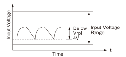
4 Output Voltage Adjust Range
The output voltage of power module can be adjusted by connecting an external resistor (Radj) between the TRIM pin and either the +Vo or ‒Vo pins.
With an external resistor (Radj) between TRIM pin and +Vo pin as shown in diagram below, output voltage will de- crease.
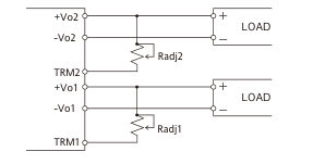
If the external resistor (Radj) is connected between the TRIM pin and ‒Vo pin, the output voltage will increase. Diagram shown below is the output voltage trim up connection.
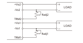
The equations and graphs for the required external resistor
PAH
(Radj) value to obtain a percentage output voltage change of ΔVo% is as shown in the next page. For output adjust down, the allowable output current have to be the same as nominal output current. For output adjust up, the allowable output current have to derate to maximun power. Refer to the below table
| Vo1(V) | Io1(A) | Vo2(V) | Io2(A) | Po(W) | |
| Ouput adjust up | 5.5 | 4.64 | 3.3 | 15 | 75 |
| 5 | 4.11 | 3.63 | 15 | 75 | |
| Nominal output | 5 | 5.1 | 3.3 | 15 | 75 |
| Output adjust down | 4.5 | 5.1 | 3.3 | 15 | 72.45 |
| 5 | 5.1 | 2.97 | 15 | 70.05 |
1)PAH75D24-5033 ‒ Output Adjustment Followings show the equations and graphs for the required external resistor to tune down and up output voltage for PAH75D24-3325 model. i) Vo1 (5V) : output adjust down Radj1(down) =( 2.5-ΔVo(4.32) )kΩ
ΔVo
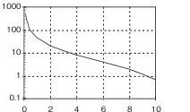
%CHANGE IN OUTPUT VOLTAGE (Δ%)
B-205
Page 64
PAH75D24
ii) Vo2 (3.3V): output adjust down Radj2 (down) =( 0.256-ΔVo(0.685)
)kΩ
ΔVo
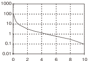
%CHANGE IN OUTPUT VOLTAGE (Δ%)
iii) Vo1 (5V): output adjust up Radj1 (up) =( 2.5-ΔVo(3.32)
)kΩ ΔVo
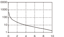
%CHANGE IN OUTPUT VOLTAGE (Δ%)
iv) Vo2 (3.3V): output adjust up PAH
Radj2 (up) =( 0.8-ΔVo(0.365)
)kΩ ΔVo
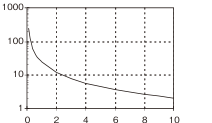
%CHANGE IN OUTPUT VOLTAGE (Δ%)
2)PAH75D24-3325 ‒ output adjustment Followings show the equations and graphs for the required external resistor to tune down and up output voltage for PAH75D24-3325 model. i) Vo1 (3.3V): output adjust down Radj1 (down) =( 3.4222-ΔVo(6.7712)
)kΩ
ΔVo
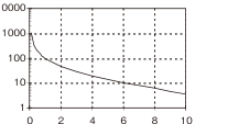
%CHANGE IN OUTPUT VOLTAGE (Δ%)
ii) Vo2 (2.5V): output adjust down Radj2 (down) =( 6.1511-ΔVo(14.9307)
)kΩ
ΔVo
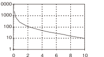
%CHANGE IN OUTPUT VOLTAGE (Δ%)
B-206
iii) Vo1 (3.3V): output adjust up Radj1 (up) =( 2.0599-ΔVo(5.11)
)kΩ
ΔVo
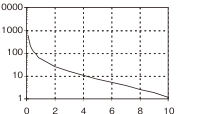
%CHANGE IN OUTPUT VOLTAGE (Δ%)
iv) Vo2 (2.5V): output adjust up Radj2 (up) =( 6.1757-ΔVo(10)
)kΩ ΔVo
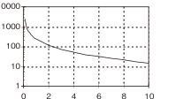
%CHANGE IN OUTPUT VOLTAGE (Δ%)
5 Output Ripple & Noise Measurement Method
The standard measurement for output ripple and noise are based on normal probe with 20MHz bandwidth scope. Upon measurement of the ripple voltage, make sure that the oscilloscope probe leads are not too long.
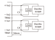
Specification The ripple & noise specification for operating range be- tween ‒40℃ to 100℃ is shown below. i)5.0V & 3.3V
200mV
100mV
TBP
-40℃ 0℃ 85℃ 100℃
Baseplate temperature
ii)2.5V & 1.8V
150mV
75mV
TBP
-40℃ 0℃ 85℃ 100℃
Baseplate temperature
iii)JEITA measurement method Below results are for reference only which is based on JEITA standard (JEITA probe with 100MHz bandwidth scope). The measurement condition is Vin=24V and Tbp=25℃.
Page 65
PAH75D24
PAH75D24-5033
| Load Condition | Vo1 (5V) | Vo2 (3.3V) |
|---|---|---|
| Io1=15A ; Io2=0A | 30mV | 42mV |
| Io1=0A ; Io2=15A | 31mV | 43mV |
| Io1=5A ; Io2=15A | 32mV | 45mV |
PAH75D24-3325
| Load Condition | Vo1 (3.3V) | Vo2 (2.5V) |
|---|---|---|
| Io1=15A ; Io2=0A | 20mV | 18mV |
| Io1=0A ; Io2=15A | 22mV | 19mV |
| Io1=5A ; Io2=15A | 23mV | 21mV |
6 Maximum Line Regulation
Maximum line regulation is the maximum output voltage change when the input voltage is slowly varied within the input voltage range. The measurement point for the input and output voltages are ±Vin, ±Vo1 and ±Vo2 respectively.
7 Maximum load regulation
Maximum load regulation is the maximum output voltage value change when varying the load current slowly within the standard output current range. The measurement point for the input and output voltages are ±Vin, ±Vo1 and ± Vo2 respectively.
8 Brownout
There will be output voltage overshoot during brown-out (momentary input line off) condition.
9 Over Current Protection
The PAH75D24 SERIES is equipped with an over current protection circuit. When the short or overload condition is removed, the output will automatically recover. This setting is fixed and cannot be varied externally. If the short or overload condition continues, the power module could be damaged due to the heat condition.
10 Over Voltage Protection
There are 2 types of over voltage protection method available for PAH75D24 SERIES. In the standard model, a latching shutdown method is adopted. For this method there are two ways to reset the power module after OVP protection triggers. They are by (i) giving a pulse to the control pin or (ii) recycling the input voltage. In the /V op- tional model, the power module will shutdown after OVP protection triggers but will recover automatically when over voltage is removed.
11 Thermal Protection
The PAH75D24 SERIES have a thermal protection circuit that senses the baseplate temperature between the range of 105℃ to 130℃ for an over temperature condition.
Under a condition where the ambient temperature or the power module internal temperature rises excessively, the thermal protection circuit will shut down the power module. The power module will recover automatically when the baseplate temperature cools down.
12 ON/OFF Control (CNT)
Without turning the input on and off, the output can be en- abled and disabled using this function. This control circuit is on the input side of the power module; CNT terminal pin. There are two options available in this function, which are Negative Logic and Positive Logic. In the standard model where Negative Logic is used, power module will turn on when the CNT terminal pin is shorted to ‒Vin or a low logic voltage is provided. The Power module will turn off when CNT terminal pin is open or Logic high is provided. In the /P optional model where Positive Logic is used, the control method is vice versa to Negative logic. The maximum CNT pin voltage when it is opened is 7V.
The maximum low logic sourcing current is 0.6mA. When using this function, attach a 0.1uF capacitor between the CNT and ‒Vin terminals as close as possible.
PAH
Remote ON/OFF control can also be exercised by opening or closing the contacts of a switch or relay, or by operating a transistor as a switch in series with the CNT terminal. Standard remote ON/OFF control circuit is provided in the primary circuit. For secondary control, isolation can be achieved through use of an optocoupler or relay. CNT Connection Method
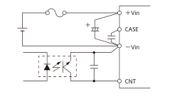
Below tables summarize the CNT levels and output states with different logic types.
a)Negative Logic: (Standard model)
| CNT Level for INPUT ‒V | OUTPUT |
| H (more than 2.0V) or Open | OFF |
| L (less than 1.0V) or Short | ON |
b)Positive Logic: (/P option)
| CNT Level for INPUT ‒V | OUTPUT |
| H (more than 2.0V) or Open | ON |
| L (less than 1.0V) or Short | OFF |
13 Operation Temperature
The baseplate temperature range for PAH75D24 SERIES is from -40℃ to 100℃.
14 Operation Humidity
Avoid the buildup of condensation on or in the power module.
B-207
Page 66
PAH75D24
15 Storage Temperature
Please note that sudden temperature changes can cause condensation buildup, and other harmful affects to each terminal solder.
16 Storage Humidity
High temperature and humidity can cause the terminals on the module to oxidize. The quality of the solder will be- come worse.
17 Cooling Method
The operating temperature is specified by the baseplate temperature. Various cooling methods are possible such as using heatsink or chassis of the equipment. If the temperature is very high, fan is recommended.
18 Baseplate Temperature vs. Output Regulation
This is the output voltage change ratio when varying the baseplate operation temperature. PAH
19 Withstand Voltage
The power module is designed to withstand 1.5kVDC be- tween the input to the baseplate and input to output for 1 minute. In the case that the withstand voltage is tested in the incoming goods test, etc., please set the limit of the test equipment to 20 mA. The applied voltage must be increased gradually from zero to the testing value, and then decreased gradually at shutdown. Do not use a timer where a pulse of several times the applied voltage can be generated. This could cause damage to the module. Be sure to short all the input and output pins as shown below.
〈Input ~ Baseplate〉
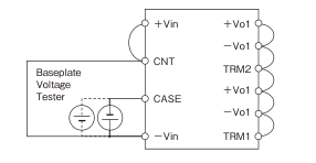
1.5kVDC 1 min. (20mA) Note: Please be sure to short all the input & output pins as shown above.
B-208
〈Input ~ Output〉
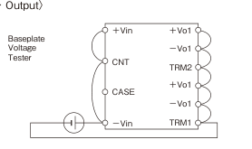
1.5kVDC
1 min. (20mA)
Note: Please be sure CASE is not shorted to any pins.
20 Isolation Resistance
The isolation resistance is more than 100MΩ at 500VDC when tested with a DC isolation tester between the output and the baseplate. Make sure that during testing, the isolation testers does not produce a high pulse when the applied voltage is varied. Ensure that the tester is fully discharged after the test.
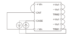
21 Vibration
Please refer to the power module mounting in the PAH75D24 SERIES Handbook in order to achieve vibration level stated in the specification.
22 Shock
Value for the conditions of our shipping and packaging.
23 Others
The performance of a system with Power Module is influ- enced according to various conditions -- PCBs, chassis, mechanics, heat dissipation. Please evaluate actual products, and confirm its performance. Please refer to "Power Module Application Note" for thermal design and mounting direction.
Page 67
PAH75D48
PAH 5 48 S
S nst
ction an a
- PAH300S24, 350S24 Instruction Manual
B-176Page
- PAH50S48 ~200S48 Instruction Manual
B-182Page
- PAH300S48, 350S48 Instruction Manual
B-189Page
B-196Page
- PAH450S48 Instruction Manual
- PAH200H Instruction Manual
B-216Page
Before Using This Power Module
Pay attention to all warnings and cautions before using this unit. Incorrect usage could lead to an electric shock, damage to the unit, or a fire hazard. Be sure to read below warnings and cautions before using the power module.
Warning
- Do not touch heatsink and case which may be hot.
- Do not open the case and touch the internal components. They may have high temperature or high voltage which may get you in electric shock or burned.
- When the unit is operating, keep your hands and face away from the unit. You may get injured by an accidents.
Caution
- Confirm connections to input/output terminals and signal ter- minals are correct as indicated in the instruction manual.
- Attach a fast blow type external fuse to each module to en- sure safety operation and to acquire each safety standard ap- proval.
- This power module is designed for professional installation within an end user equipment.
- The input supply, 36 - 76VDC must be isolated from the
mains primary power supply by reinforced insulation in accordance with EN60950/UL1950.
- Equipment with these products mounted inside must be protected to prevent contact with by technical service staff or dropped tools, etc. When repairing the equipment, please be sure to turn off input sourse, and confirm that input and output voltage has dropped down to a safe level.
- The application circuits and their parameter are for reference only. Be sure to verify effectiveness of application circuits and their parameters before finalizing circuit design.
- The information in this document is subject to change without notice. For actual design-in, please refer to the latest publica- tions of data sheet, etc., for the most up-to-date specifica- PAH tions of the unit.
- No part of this document may be copied or reproduced in any form or by any mean without prior written consent of Densei- Lambda.
- Do not inject abnormal voltage to output or signal pins. Es- pecially, when inject negative voltage or voltage exceeding rated output voltage to output pins might cause damage to internal output capacitor (Functional Polymerized Capacitor).
1. Terminal Pin Configurations
-Vin : Negative Input Terminal
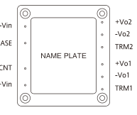
CASE : Baseplate Terminal CNT : ON/OFF Control Terminal +Vin : Positive Input Terminal +Vo2 : CH2 Positive Output Terminal -Vo2 : CH2 Negative Output Terminal TRM2 : CH2 Output Voltage Adjustment Terminal +Vo1 : CH1 Positive Output Terminal -Vo1 : CH1 Negative Output Terminal TRM1 : CH1 Output Voltage Adjustment Terminal
2. Functions on Specifications
1 BASIC CONNECTION
Input voltage measurement point Output ripple & noise measurement point
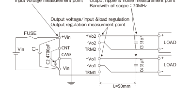
Note: This diagram is for Negative Logic “ON/OFF” Option.
2 External Components
The table below shows the recommended values for the above external components.
| Item | Vo1 | Vo2 |
| F1 | 250V 5A (UL approved and fast acting) | |
| C1 | Tbp = -20°C to 100°C: 100V 33uF E-cap. (Use low ESR type E-cap such as KME series of Nippon Chemi-con) Tbp = -40°C to 100°C : 100V 33uF Ceramic cap. | |
| C2 | Ceramic capacitor: 2kVAC 4700pF | |
| C3, C4 | Ceramic capacitor: 33uF | |
B-209
Page 68
PAH75D48
PAH75D48 SERIES module is not internally fused. To ensure safe operation and to receive each safety standard approval, please connect an external fuse F1 as shown in the diagram above.
Input capacitor C1 is recommended to stabilize the module when the module is powered from a high impedance source. Capacitor C2 is used to absorb noise coming from the module itself. This capacitor will also help the EMI performance of the module.
The function of capacitor C3 is to reduce the output ripple of the power module and high frequency noise that is produced by the module.
If in any application that an input reversal connection is possible, a protective diode which is connected across +Vin and -Vin is recommended.
3 Input Voltage Range
The operating input voltage range of PAH75D48 SERIES is 36 - 76VDC. The maximum allowable input ripple volt- PAH age (Vrpl) is 4V. Any ripple that exceeds this value might cause the module to become unstable.
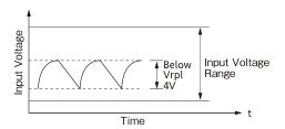
4 Output Voltage Adjust Range
The output voltage of power module can be adjusted by connecting an external resistor (Radj) between the TRIM pin and either the +Vo or ‒Vo pins. There are two options available for the trim function for models 5033 & 3325, which are standard & /Z option.
With an external resistor (Radj) between TRIM pin and +Vo pin, output voltage will decrease as shown in diagram be- low.
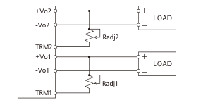
If the external resistor (Radj) is connected between the TRIM pin and ‒Vo pin, the output voltage will increase. Diagram shown below is the output voltage trim up connection.
B-210
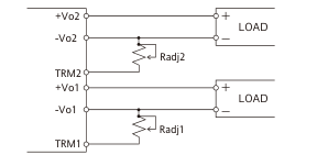
The equations and graphs for the required external resistor (Radj) value to obtain a percentage output voltage change of ΔVo% is as shown in the next page.
For output adjust down, the allowable output current have to be the same as nominal output current. For output adjust up, the allowable output current have to derate to maximun power. Refer to the below table
| Vo1(V) | Io1(A) | Vo2(V) | Io2(A) | Po(W) | |
| Ouput adjust up | 5.5 | 4.64 | 3.3 | 15 | 75 |
| 5 | 4.11 | 3.63 | 15 | 75 | |
| Nominal output | 5 | 5.1 | 3.3 | 15 | 75 |
| Output adjust down | 4.5 | 5.1 | 3.3 | 15 | 72.45 |
| 5 | 5.1 | 2.97 | 15 | 70.05 |
1) PAH75D48-5033 ‒ Output Adjustment Followings show the equations and graphs for the required external resistor to tune down and up output voltage for PAH75D48-5033 standard model.
i) Vo1 (5V): output adjust down Radj1(down) =( 2.5 -ΔVo (4.32) ) kΩ
ΔVo
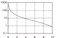
%CHANGE IN OUTPUT VOLTAGE (Δ%)
ii) Vo2 (3.3V): output adjust down Radj2(down) =( 0.256 -ΔVo(0.685)
) kΩ
ΔVo
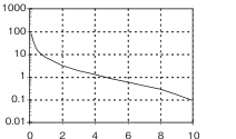
%CHANGE IN OUTPUT VOLTAGE (Δ%)
Page 69
PAH75D48
iii) Vo1 (5V): output adjust up Radj1(up) =( 2.5 -ΔVo(3.32)
) kΩ ΔVo
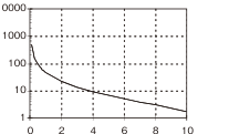
%CHANGE IN OUTPUT VOLTAGE (Δ%)
iv) Vo2 (3.3V): output adjust up Radj2(up) =( 0.8-ΔVo(0.365)
) kΩ ΔVo
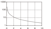
%CHANGE IN OUTPUT VOLTAGE (Δ%)
2) PAH75D48-5033/Z ‒ Output Adjustment (/Z Option) Followings show the equations and graphs for the required external resistor to tune down and up output voltage for PAH75D48-5033/Z optional model.
i) Vo1 (5V): output adjust down Radj1(down) =( 2.5 -ΔVo(4.32) )kΩ
ΔVo
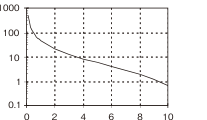
%CHANGE IN OUTPUT VOLTAGE (Δ%)
ii) Vo2 (3.3V): output adjust down Radj2(down) =( 0.256 -ΔVo(0.685) )kΩ
ΔVo
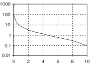
%CHANGE IN OUTPUT VOLTAGE (Δ%)
iii) Vo1 (5V): output adjust up Radj1(up) =( 2.5 -ΔVo(3.32) )kΩ
ΔVo
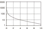
%CHANGE IN OUTPUT VOLTAGE (Δ%)
iv) Vo2 (3.3V): output adjust up Radj2(up) =( 0.8-ΔVo(0.365) )kΩ
ΔVo
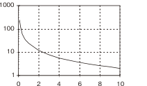
%CHANGE IN OUTPUT VOLTAGE (Δ%)
3) PAH75D48-3325 ‒ output adjustment (Standard) Followings show the equations and graphs for the required external resistor to tune down and up output voltage for PAH75D48-3325 standard model.
i) Vo1 (3.3V): output adjust down Radj1(down) =( 3.4814 -ΔVo(2.69) )kΩ
ΔVo
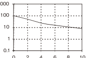
PAH
%CHANGE IN OUTPUT VOLTAGE (Δ%)
ii) Vo2 (2.5V): output adjust down Radj2(down) =( 0.51 -ΔVo(1.53) )kΩ
ΔVo
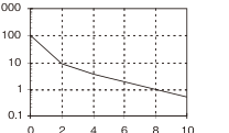
%CHANGE IN OUTPUT VOLTAGE (Δ%)
iii) Vo1 (3.3V): output adjust up Radj1(up) =( 2.0956 -ΔVo )kΩ
ΔVo
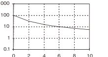
%CHANGE IN OUTPUT VOLTAGE (Δ%)
iv) Vo2 (2.5V): output adjust up Radj2(up) =( 2.04 -0.510ΔVo )kΩ
ΔVo
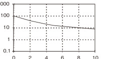
%CHANGE IN OUTPUT VOLTAGE (Δ%)
B-211
Page 70
PAH75D48
4) PAH75D48-3325/Z ‒ Output Adjustment (/Z Option) Followings show the equations and graphs for the required external resistor to tune down and up output voltage for PAH75D48-3325/Z optional model.
i) Vo1 (3.3V): output adjust down Radj1(down) =( 3.4222 -ΔVo(6.7712) )kΩ
ΔVo
10000
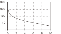
%CHANGE IN OUTPUT VOLTAGE (Δ%)
ii) Vo2 (2.5V): output adjust down Radj2(down) =( 6.1511-ΔVo(14.9307) )kΩ
ΔVo
10000
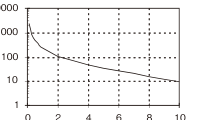
PAH
%CHANGE IN OUTPUT VOLTAGE (Δ%)
iii) Vo1 (3.3V): output adjust up Radj1(up) =( 2.0599-ΔVo(5.11) )kΩ
ΔVo
10000
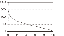
%CHANGE IN OUTPUT VOLTAGE (Δ%)
iv) Vo2 (2.5V): output adjust up Radj2(up) =( 6.1757 -ΔVo(10) )kΩ
ΔVo
10000
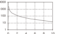
%CHANGE IN OUTPUT VOLTAGE (Δ%)
5) PAH75D48-3318 ‒ output adjustment Followings show the equations and graphs for the required external resistor to tune down and up output voltage for PAH75D48-3318 model. There is no trim option for this model.
B-212
i) Vo1 (3.3V): output adjust down Radj1(down) =( 3.4814 -ΔVo(2.69) )kΩ
ΔVo
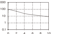
%CHANGE IN OUTPUT VOLTAGE (Δ%)
ii) Vo2 (1.8V): output adjust down Tune-down of Vo2 is not applicable.
iii) Vo1 (3.3V): output adjust up Radj1(up) =( 2.0956 -ΔVo )kΩ
ΔVo
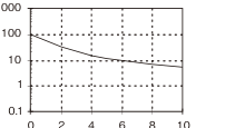
%CHANGE IN OUTPUT VOLTAGE (Δ%)
iv) Vo2 (1.8V): output adjust up Radj2(up) =( 9.28 -ΔVo )kΩ
ΔVo
10000
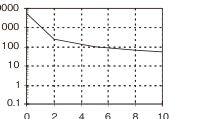
%CHANGE IN OUTPUT VOLTAGE (Δ%)
6) PAH75D48-2518 ‒ Output Adjustment Followings show the equations and graphs for the required external resistor to tune down and up output voltage for PAH75D48-2518 model. There is also no trim option for this model. i) Vo1 (2.5V) &Vo2 (1.8V): output adjust down Tune down of Vo1 and Vo2 is not applicable
ii) Vo1 (2.5V): output adjust down Radj1(up) =( 2.542 -ΔVo )kΩ
ΔVo
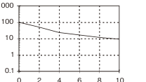
%CHANGE IN OUTPUT VOLTAGE (Δ%)
Page 71
PAH75D48
iii) Vo2 (1.8V): output adjust up Radj2(up) =( 9.28 -ΔVo )kΩ
ΔVo
10000
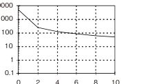
%CHANGE IN OUTPUT VOLTAGE (Δ%)
5 Output Ripple & Noise Measurement Method
The standard measurement for output ripple and noise are based on normal probe with 20MHz bandwidth scope. Upon measurement of the ripple voltage, make sure that the oscilloscope probe leads are not too long.
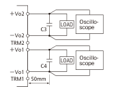
1) Specification The ripple & noise specification for operating range be- tween ‒40℃ to 100℃ is shown below.
ⅰ) 5V & 3.3V
200mV
100mV
TBP
-40℃ 0℃ 85℃ 100℃
Baseplate temperature
ⅱ) 2.5V & 1.8V
150mV
75mV
TBP
-40℃ 0℃ 85℃ 100℃
Baseplate temperature
ⅲ) JEITA measurement method Below results are for reference only which is based on JEITA standard (JEITA probe with 100MHz bandwidth scope). The measurement condition is Vin=48V and Tbp =25℃.
PAH75D48-5033
| Load Condition | Vo1 (5V) | Vo2 (3.3V) |
|---|---|---|
| Io1=15A ; Io2=0A | 50mV | 43mV |
| Io1=0A ; Io2=15A | 40mV | 36mV |
| Io1=5A ; Io2=15A | 51mV | 60mV |
PAH75D48-3325
| Load Condition | Vo1 (3.3V) | Vo2 (2.5V) |
|---|---|---|
| Io1=15A ; Io2=0A | 46mV | 33mV |
| Io1=0A ; Io2=15A | 48mV | 46mV |
| Io1=5A ; Io2=15A | 42mV | 33mV |
PAH75D48-3318
| Load Condition | Vo1 (3.3V) | Vo2 (1.8V) |
|---|---|---|
| Io1=15A ; Io2=0A | 49mV | 33mV |
| Io1=0A ; Io2=15A | 46mV | 48mV |
| Io1=5A ; Io2=15A | 42.5mV | 40mV |
PAH75D48-2518
| Load Condition | Vo1 (2.5V) | Vo2 (1.8V) |
|---|---|---|
| Io1=15A ; Io2=0A | 32mV | 36mV |
| Io1=0A ; Io2=15A | 35mV | 34mV |
| Io1=5A ; Io2=15A | 40.5mV | 35mV |
6 Maximum Line Regulation
Maximum line regulation is the maximum output voltage change when the input voltage is slowly varied within the input voltage range. The measurement point for the input and output voltages are ±Vin , ±Vo1 and ±Vo2 respectively.
7 Maximum load regulation
Maximum load regulation is the maximum output voltage
PAH
value change when varying the load current slowly within the standard output current range. The measurement point for the input and output voltages are ±Vin, ±Vo1 and ± Vo2 respectively.
8 Brownout
There will be output voltage overshoot during brown-out (momentary input line off) condition.
9 Over Current Protection
The PAH75D48 SERIES is equipped with an over current protection circuit. When the short or overload condition is removed, the output will automatically recover. This setting is fixed and cannot be varied externally. If the short or overload condition continues, the power module could be damaged due to the heat condition.
10 Over Voltage Protection
There are 2 types of over voltage protection method available for PAH75D48 SERIES. In the standard model, a latching shutdown method is adopted. For this method there are two ways to reset the power module after OVP protection triggers. They are by (i) giving a pulse to the control pin or (ii) recycling the input voltage. In the /V op- tional model, the power module will shutdown after OVP protection triggers but will recover automatically when over voltage is removed.
11 Thermal Protection
The PAH75D48 SERIES have a thermal protection circuit that senses the baseplate temperature between the range of 105℃ to 130℃ for an over temperature condition. Under a condition where the ambient temperature or the
B-213
Page 72
PAH75D48
power module internal temperature rises excessively, the thermal protection circuit will shut down the power module. The power module will recover automatically when the baseplate temperature cools down.
12 ON/OFF Control (CNT)
Without turning the input on and off, the output can be en- abled and disabled using this function. This control circuit is on the input side of the power module; CNT terminal pin. There are two options available in this function, which are Negative Logic and Positive Logic. In the standard model where Negative Logic is used, power module will turn on when the CNT terminal pin is shorted to ‒Vin or a low logic voltage is provided. The Power module will turn off when CNT terminal pin is open or Logic high is provided. In the /P optional model where Positive Logic is used, the control method is vice versa to Negative logic.
The maximum CNT pin voltage when it is opened is 7V. The maximum low logic sourcing current is 0.6mA. When using this function, attach a 0.1uF capacitor between the CNT and ‒Vin terminals as close as possible. PAH
Remote ON/OFF control can also be exercised by opening or closing the contacts of a switch or relay, or by operating a transistor as a switch in series with the CNT terminal.
Standard remote ON/OFF control circuit is provided in the primary circuit. For secondary control, isolation can be achieved through use of an optocoupler or relay. CNT Connection Method
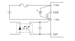
Below tables summarize the CNT levels and output states with different logic types.
a) Negative Logic: (Standard model)
| CNT Level for INPUT ‒V | OUTPUT |
| H (more than 2.0V) or Open | OFF |
| L (less than 1.0V) or Short | ON |
b) Positive Logic: (/P option)
| CNT Level for INPUT ‒V | OUTPUT |
| H (more than 2.0V) or Open | ON |
| L (less than 1.0V) or Short | OFF |
13 Operation Temperature
The baseplate temperature range for PAH75D48 SERIES is from -40℃ to 100℃.
B-214
14 Operation Humidity
Avoid the buildup of condensation on or in the power module.
15 Storage Temperature
Please note that sudden temperature changes can cause condensation buildup, and other harmful affects to each terminal solder.
16 Storage Humidity
High temperature and humidity can cause the terminals on the module to oxidize. The quality of the solder will be- come worse.
17 Cooling Method
The operating temperature is specified by the baseplate temperature. Various cooling methods are possible such as using heatsink or chassis of the equipment. If the temperature is very high, fan is recommended.
18 Baseplate Temperature vs. Output Regulation
This is the output voltage change ratio when varying the baseplate operation temperature.
19 Withstand Voltage
The power module is designed to withstand 1.5kVDC be- tween the input to the baseplate and input to output for 1 minute. In the case that the withstand voltage is tested in the incoming goods test, etc., please set the limit of the test equipment to 20 mA. The applied voltage must be increased gradually from zero to the testing value, and then decreased gradually at shutdown. Do not use a timer where a pulse of several times the applied voltage can be generated. This could cause damage to the module. Be sure to short all the input and output pins as shown below.
〈Input - Baseplate〉
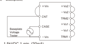
1.5kVDC 1 min. (20mA)
Note: Please be sure to short all the input & output pins as shown above.
Page 73
PAH75D48
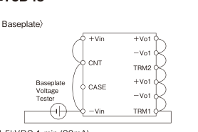
〈Input - Baseplate〉
1.5kVDC 1 min.(20mA) Note: Please be sure CASE is not shorted to any pins.
20 Isolation Resistance
The isolation resistance is more than 100MΩ at 500VDC when tested with a DC isolation tester between the output and the baseplate. Make sure that during testing, the isolation testers does not produce a high pulse when the applied voltage is varied. Ensure that the tester is fully discharged after the test.
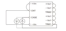
21 Vibration
Please refer to the power module mounting in the PAH75D48 SERIES Handbook in order to achieve vibration level stated in the specification.
22 Shock
Value for the conditions of our shipping and packaging.
23 Others
The performance of a system with Power Module is influ- enced according to various conditions -- PCBs, chassis, mechanics, heat dissipation. Please evaluate actual products, and confirm its performance. Please refer to "Power Module Application Note" for thermal design and mounting direction.
PAH
B-215
Page 74
PAH200H
PAH 00H nst
ction an a
- PAH300S24, 350S24 Instruction Manual
B-169Page
- PAH50S48 ~200S48 Instruction Manual
B-177Page
- PAH300S48, 350S48 Instruction Manual
B-182Page
B-190Page
- PAH450S48 Instruction Manual
- PAH75D Instruction Manual
B-199Page
Before Using This Power Module
Be sure to take note of precautions and warnings indicated in this manual when using this product. Improper us- age may lead to electric shock or fire. Be sure to read this instruction manual thoroughly before using this product.
Caution
- There are high voltage and high temperature components within this product. Refrain from disassembling this product or touching its internal components as this may lead to elec- tric shock or burned.
- When the unit is operating, keep your hands and face away
PAH from the unit. You may get injured by accident.
- Confirm connections to input/output terminals and signal ter- minals are correct as indicated in the instruction manual.
- Attach a fast blow type external fuse to each module to ensure safety operation and compliance to each safety stan- dard approval.
- This power module is designed for professional installation within the end user equipment.
- Use isolated voltage by reinforced or double insulation as
input power source.
- Do not inject abnormal voltage to output terminal and signal terminal from the outside. The injection of reverse voltage or over voltage exceeding nominal output voltage to output terminals might cause Damage to internal output capacitor (Functional Polymerized Capacitor)
- The application circuits and their parameter are for reference only. Be sure to verify effectiveness of application circuits and their parameters before finalizing circuit design.
- The information in this document is subject to change with- out prior notice. For actual design-in, please refer to the lat- est publications of data sheet, etc., for the most up-to-date specifications of the unit.
- No part of this document may be copied or reproduced in any for, or by any mean without prior written consent of Den- sei-Lambda.
Note : CE Marking
CE Marking, when applied to a product covered by instruction manual, indicates compliance with the low voltage directive which complies with EN60950
1. Terminal Explanation
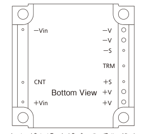
[Input terminal ] -Vin: -Input Terminal CNT: ON/OFF Control Terminal +Vin: +Input Terminal
[ Output terminal ] -V: -Output Terminal -S: -Remote Sensing Terminal TRM: Output Voltage Trimming Terminal +S: +Remote Sensing Terminal +V: +Output Terminal
Please ensure good connectivity to minimize the connection resistance for terminal +Vin, -Vin, +V and ‒V.
Input and Output Terminal Configurations(Bottom View)
B-216
Page 75
PAH200H
2. Explanation on Specifications
1 Input Voltage Range
Input voltage Range for PAH200H48 Series is indicated below. Input Voltage Range: 36 - 76VDC Maximum Applied Surge Voltage:
100VDC, 100ms
Basically, ripple voltage (Vrpl) which results from rectifica- tion and filtering of commercial AC line is included within the input voltage as shown in Fig.1-1. Ripple voltage must be limited within the voltage described below. Allowable input ripple voltage: 4Vp-p
When this value is exceeded, the output ripple voltage be- comes large. Note that abrupt input voltage change may cause the output voltage to fluctuate transitionally. Also, input voltage waveform peak value must not exceed above input voltage range.
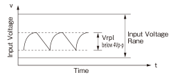
Fig.1-1 Input Ripple Voltage
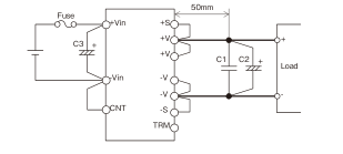
Fig.1-2 Basic Connection
(Standard Model: Negative Logic type for ON/OFF Control) Input Fuse PAH200H48 Series module is not internally fused. To en- sure safe operation and to receive each Safety Standard approval, please connect an external fuse (fast-blow type) as shown in Fig.1-2. Fuse must be connected to the +Vin side if ‒Vin side is used as a ground, or fuse must be connected to ‒Vin side if +Vin side is used as a ground.
Recommended input fuse current rating:
PAH200H48: 10A
C1: 1μF, C2: 10μF To reduce spike noise voltage at the output, connect 1μF ceramic capacitor and 10µF electrolytic capacitor or tantalum capacitor between +V and ‒V within 50mm distance from the output terminals. Also, take note that output spike noise voltage could vary according to PCB wiring design.
Maximum capacitance of electrolytic capacitor that can be connected between +V and ‒V, is total 10,000µF.
C3: Input capacitor C3 is recommended to stabilize to module when the module is powered from a high impedance source. Select the electrolytic capacitor with low ESR and suffi- cient allowable ripple current. Verify actual ripple current value by actual measurement.
Recommended capacitor value: 100µF and above (voltage rating 100V or above)
Note) 1. Use low impedance electrolytic capacitor with excellent temperature characteristics. (Nippon Chemicon LXV Series or equivalent) 2. When input line inductance becomes excessively high due to insertion of choke coil operation of the power module could become unstable. For this case, in- crease C3 value more than the value indicated above.
PAH
- When ambient temperature becomes lower than -20ºC, connect two capacitors indicate above in parallel
C4: When switches or connectors are used between input source and PAH200H48 Series input terminals, impulse surge voltage is generated due to input throw-in by switch on/off or due to inserting/removing of power module from the active line. For this case, connect an additional electrolytic capacitor C4 as shown in fig.1-3 and fig.1-4.
Recommended Capacitor: 100µF and above (Voltage Rating 100V or above)
Also, in-rush current flows at line throw-in. Therefore, be sure to verify capability of switch or fuse to withstand I2t at line throw-in.
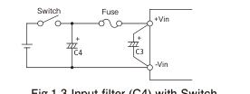
Fig.1-3 Input filter (C4) with Switch
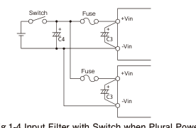
Fig.1-4 Input Filter with Switch when Plural Power
Reverse input connections Reverse input polarity would cause module damage.
B-217
Page 76
PAH200H
For cases where reverse connections are possible, connect a protective diode and fuse. Use protective diode with higher voltage rating than the input voltage, and with higher surge current rating than the fuse.
Fuse +Vin +V Load
-Vin -V
Fig.1-5 Protection for Reversed Input Connection
2 Output Voltage Adjustment Range
Output voltage could be adjusted within the range de- scribed below by external resister or variable resistor. However, take note that OVP might trigger when output voltage adjustment exceeds the ranges indicated below. Output Voltage Adjustment Range 3.3V: -15% - +15% of nominal output Voltage 1.8V, 2.5V : -20% - +10% of nominal output Voltage When increasing the output voltage reduce the output current accordingly so as not to exceed the maximum output power. For 3.3V output model, take note that when output volt- PAH age is increased, input voltage range is limited as shown in fig.2-1. Also, when output voltage is decreased under output ad- justment range, output voltage will shut off.
Remote sensing is possible even when output voltage is varied. For details on remote sensing function, please refer to “9. Remote Sensing”
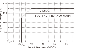
Fig.2-1 Limit of Input Voltage
Output Voltage Adjustment by external resistor or by variable resistor (1) In case of adjusting output voltage lower (1-1) Available maximum output current = rated output current (1-2)Connect an external resistor Radj(down) between the TRM terminal and ‒S terminal.
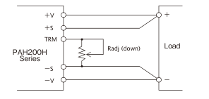
Fig.2-2 Connection for output voltage trim down (1)
B-218
(1-3)Equation of external resistor and output voltage.
(1R8, 2R5, 3R3)
100% 2
Radj (down)=
(1R5)
2.67×100% 3.67
Radj(down)=
(1R2)
1.67×100% 2.67
Radj(down)=
Radj (down) : Value of external resistor Δ(% ):
Output voltage change rate against nominal output voltage
Below graph is relation Δ% and value of external resistor.
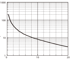
Change in Output Voltage Δ (%)
Fig.2-3 Δ(% ) vs. Radj(down) (1)
(2) In case of adjusting output voltage higher (2-1) Allowable maximum output current = value of output power ÷ output voltage (reduce maximum output current in specification.)
(2-2) Connect an external resistor Radj (up) between TRM terminal and +S terminal
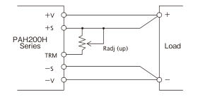
Fig.2-4 Connection for output voltage trim up (2)
(2-3) Equation of external resistor and output voltage (1R8, 2R5, 3R3)
+
(1R5) 1.26×100% +0.2
(1R2) 0.78×100% -0.22
Vo:
nominal output value of module
Radj (up) : external adjustment resistor Δ (% ): Output voltage change rate against nominal
output voltage
Ex.)To adjust to 3.63V for 3.3V nominal model, setting level is +10% , therefore Δ(% ) = 10% .
Page 77
PAH200H
Below graph is relation Δ(%) and value of external resistor.
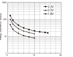
Change in Output VoltageΔ(%) Fig.2-5 Δ% vs.Radj (up) (2)
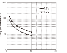
Change in Output VoltageΔ(%) Fig.2-6 Δ(%) vs.Radj (down) (3)
(3) To adjust output voltage for whole range Resistor values, as well as, connecting methods for external resistor (R1) and external variable resistor (VR) are described below.
| 1.8V | 2.5V | 3.3V | |
| R1 | 2.2k | 1k | 2.2k |
| VR | 1k | 2k | 2k |
unit: [Ω]
Table 2-3 Value of External Resistor and Variable Resistor Vo -20% , +10% (1.8V,2.5V) Vo ±15% (3.3V)
| 1.8V | 2.5V | 3.3V | |
| R1 | 5.6k | 3.3k | 5.6k |
| VR | 500 | 1k | 1k |
unit: [Ω]
Table 2-4 Value of External Resistor and Variable
Resistor (±10% Variable)
R1: ±5% Tolerance VR: ±20% Tolerance with end resistance below 1%
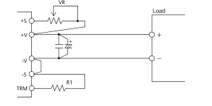
Fig.2-6 Example connection of external resistor
3 Maximum Ripple and Noise
(1) Measurement based on JEITA RC-9141 Measure according to the specified methods (Fig.3-1) based on JEITA RC-9141(Clause 7.12 and 7.13) which is described in the following. Connect ca- pacitors (C1: ceramic capacitor 1μF, C2: tantalum capacitor 10μF) at 50mm distance from the output terminals. Measure at ceramic capacitor (C1) leads as shown in fig.3-1 using coaxial cable with JEITA at- tachment. Use oscilloscope with 100MHz frequency bandwidth or equivalent.
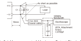
Fig.3-1 Measurement of Maximum Output Ripple & Noise Based on JEITA RC-9141 (2)Measurement using coaxial cable Measure according to Fig.3-2. Connect capacitors (C1: ceramic capacitor 1μF, C2: tantalum capacitor 10μF) PAH at 50mm distance from the output terminals. Measure at ceramic capacitor (C1) leads using coaxial cable. Use oscilloscope with 20MHz frequency bandwidth or equivalent.
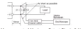
Fig.3-2 Measurement of Maximum Output Ripple & Noise Using coaxial cable
Take note that output ripple voltage and output spike noise may vary depending on PCB wiring design. Generally output ripple voltage and output spike noise can be reduced by increasing value of external capacitor.
4 Maximum Line Regulation
Maximum line regulation is the maximum value of output voltage change when input voltage is gradually varied within specified input voltage range. The measurement point for the input and output voltage are ±Vin and ±S (sense point) respectively.
5 Maximum Load Regulation
Maximum value of output voltage change when output current is gradually varied within specified output current range. The measurement point for the input and output voltage are ±Vin and ±S (sense point) respectively. When using at dynamic load mode, audible noise may be heard from the power module and output voltage fluctuation might increase.
6 Over Current Protection (OCP)
This power module has built-in OCP function. Output will recover when short circuit or overload conditions are released. OCP setting value is fixed and therefore, can not be externally adjusted. Also, take note, when
B-219
Page 78
PAH200H
output voltage drops down below lower side of adjustment range for 20ms - 50ms by output short circuit or over load conditions, output might be shut down. Output can be recovered by manual reset of the control ON/OFF terminal or by turning input line off and then turning it on again.
7 Over Voltage Protection (OVP)
This power module has built-in OVP function. OVP set point is relative to the rated output voltage value. When output voltage exceeds OVP set point, output voltage shuts down. OVP set point is fixed and therefore can not be changed. When OVP is triggered, output can be recovered by turning input line off and then turning it on again after lowering the input voltage below the voltage value indicated below or by manual reset of the control ON/OFF terminal.
Input voltage for OVP reset: 24VDC and below
/V Option (automatic recovery) The /V optional model will re-start with delay of 100ms ~ 400ms after shutdown by OCP or OVP triggering. When over voltage and over current are removed, output will re- PAH cover normally. Verifying OVP function shall be done by increasing output voltage with external resistor. For verifying OVP function, avoid applying external voltage to output terminal because this will cause power module damage.
8 Over Thermal Protection (OTP)
This power module has built-in OTP function. This function operates and shuts down the output when temperature of the power module rises abnormally. Take note that OTP will operate again unless the cause of abnormal heat of the power module is eliminated. For the details of OTP, refer to the clause of “Mounting Method and Thermal Condition”
9 Remote Sensing (+S, -S Terminal)
Remote sensing terminal is provided to compensate for voltage drop across the wiring from the power module output terminal to the load input terminal. When remote sensing function is not used (local sensing), short +S terminal to +V terminal and, -S terminal to ‒V terminal. Fig.9-1indicates connections when the remote sensing terminal is used. For optimum operations, connect electrolytic capacitor as large capacity as possible (within 10,000µF) between +V and ‒V terminal, as well as across the load terminals. Take note that voltage compensation range for line drop (voltage drop due to wiring) should be kept such that output voltage at the output terminals
is within output voltage range and the maximum power doesn't exceed Use shielded wire, twist pair, or parallel pattern to reduce noise effect. When the remote sensing terminal is used, if the load wiring impedance is large, output power may disrupt the stability. To reduce the load wiring impedance, wiring should be thick and short as much
B-220
as possible. When using the lead wiring, the wire should be twist pair, or when using the pattern, use the pattern layout as shown in fig.9-3 to reduce the impedance as small as possible.
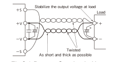
Fig.9-1 Remote Sensing in Use
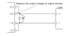
Fig.9-2 Remote Sensing Not in Use (Local Sensing)
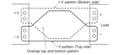
Fig.9-3 Example of Load Wiring Pattern Layout in using the double-sided PCB
10 ON/OFF Control (CNT Terminal)
Without turning the input supply on and off, the output can be enabled and disabled using this function. This function also can be used for output sequence of plural modules. There are two kind of logic control, negative logic control and positive logic control, depend on the option selected. ON/OFF control circuit is on the primary side (the input side), CNT Terminal pin. For secondary control, isolation can be achieved through the use of a opto coupler or relay.
| Logic | CNT Terminal Level to -Vin Terminal | Output status | |
|---|---|---|---|
| Standard | Negative Logic | H Level (4V≦H≦35V) or Open | OFF |
| [/V option] | L Level (0V≦H≦0.8V) or Short | ON | |
| [/P option] | Positive Logic | H Level (4V≦H≦35V) or Open | ON |
| [/PV option] | L Level (0V≦H≦0.8V) or Short | OFF |
*When control function is not used for the Standard, CNT terminal is shorted to ‒Vin terminal. *When using long wiring, for prevention of noise, attach a 0.1µF capacitor between CNT Terminal and ‒Vin terminal. *At L level, maximum source current from CNT terminal to ‒Vin terminal is 0.5mA *The maximum CNT Terminal voltage is 35V. (1) Output ON/OFF control
| Transistor, Relay or Equivalent | +Vin CNT PAH200 series -Vin |
Page 79
PAH200H
(2) Secondary (output side) control
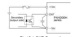
Fig.10-1 CNT Connection
11 Parallel Operation
Parallel Operation can not be used.
12 Series Operation
Series Operation is possible for PAH200H Series. For the number of maximum series connection, please contact us (A)Series Operation in High Output Voltage When Series Operation is used to obtain Higher Output Voltage, a bypass diode is needed to prevent the reverse voltage (refer Fig12-1.) The selection guide for this bypass diode is described below : Condition of selection, bypass diode D1, D2 1. Peak Repeated Reverse Voltage VRRM≧duplicate of nominal output voltage of the power supply. 2. Average output current Io≧duplicate of nominal output current of the power supply. 3. Forward voltage VF≧The lowest (schottky barrier diode and equivalent) Output reverse maximum applied voltage: 0.6VDC and
below
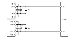
Fig.12-1 Series Operation for High Output Voltage (B) ± Output Series Operation When +load and ‒load is completely separated the bypass diode is not required.
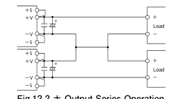
Fig.12-2 ± Output Series Operation
13 Operating Ambient Temperature
According to ambient temperature, output load should derated accordingly (refer to Mounting Method & Terminal Condition). There is no restriction on mounting direction
but there should be enough consideration for airflow so that heat does not accumulate around the power module vicinity. Determine external components configuration and mounting direction on PCB such that air could flow through power module at forced air cooling or convection cooling. For better reliability, derating of ambient temperature is recommended. For details on derating, refer to “Mounting Method & Thermal Condition”.
14 Operatin Ambient Humidity
Take note that moisture could lead to power module ab- normal operation or damage.
15 Storage Ambient Temperature
Abrupt temperature change would cause condensation built-up that leads to poor solderability of terminals of the power supply.
16 Storage Ambient Humidity
High temperature and humidity can cause the terminals on the module to oxidize. The quality of the solder will be- come worse.
PAH
17 Cooling Method
Forced air cooling is recommended. Convection cooling is also possible. For the details of derating, refer to“Mounting Method and Thermal condition”
18 Ambient Temperature vs. Output Voltage Drift
Temperature coefficient is defined as the rate of voltage change when ambient temperature is changed during op- eration.
19 Withstand Voltage
This power module is designed to have a withstand voltage of 1.5kVDC between input and output. When conducting withstand voltage test during incoming inspection, be sure to apply DC voltage. Also, set the current limit value of the withstand voltage testing equipment to 10mA. Be sure to avoid conducting test with AC voltage because this would cause power module damage. Furthermore, avoid throw in or shut off of the testing equipment when applying or when shutting down the test voltage. Instead, gradually increase or decrease the applied voltage. Take note especially not to use the timer of the test equipment because when the timer switches the applied voltage off, impulse voltage
which has several times the magnitude of the applied voltage is generated causing damage to the power module. Short the output side as shown in fig.19-1.
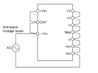
1.5kVAC 1minute (20mA) Fig.19-1 Withstand Voltage Test for Input-Output
B-221
Page 80
PAH200H
21 Vibration
20 Insulation Resistance
Vibration of power module is defined in case of mounting
Use DC insulation tester (MAX 500V) between output and
on PCB.
input. Insulation resistance value is 100MΩ and above at 500VDC applied voltage. Make sure that during testing, the isolation testers does not produce a high pulse when the applied voltage is varied. Ensure that the tester is fully 23 Shock discharged after the test.
Value for the conditions of out shipping and packing.
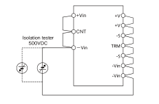
100M Ω and above at 500VDC Fig.20-1 Isolated test
3. Mounting Method and Thermal Condition
PAH200H48-1R8 (include /P, /V, /PV option)
1 Output Derating
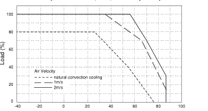
PAH (1)Output Derating by ambient temperature There is no restriction on mounting direction but there should be enough consideration for airflow so that heat does not accumulate around the power module vicinity. Determine external components configuration and mounting direction on PCB such that air could flow through power module at forced air cooling or convection cooling. Take note, output power derating
Ambient Temperature (℃) Fig.1-2
is needed as shown in followings. The derating curves provided is based on the below set-up condition.
PAH200H48-2R5 (include /P, /V, /PV option)
PCB PCB
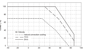
CL
25.4mm Power Module
Top view
Ta and air velocity measurement point 12.7mm
Airflow
Airflow
Fig.1-1 Output derating set-up condition
Ambient Temperature (℃) Fig.1-3
Fig. 1-2, 1-3, and 1-4 shows output derating vs ambient temperature.
PAH200H48-3R3 (include /P, /V, /PV option)
In this case, natural convection cooling means occurance of 0.2m/s airflow due to self heating of the power mod-
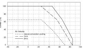
ule. If the product is used out of derating curve, they shut down by OTP (over temperature protection). Please note that OTP cannnot operate correctly when cooling is concentrated on thermal detector only
Output derating by ambient temperature Vin=48VDC at standard vertical mounting
Ambient Temperature (℃) Fig.1-4
B-222
Page 81
PAH200H
(2)Output derating by PCB When use with different measurement conditions from output derating by ambient temperature, use output derating by PCB temperature as in Fig.1-6. PCB temperature is decided by temperature of thermal sensor in below Fig.1-5. As the thermal sensor terminals are exposed, when connecting thermocouple, please take sufficient insulation from terminals. Over Thermal Protection of power module is achieved by detecting the PCB temperature through thermal sensor. When the module operates over the output derating curve of PCB temperature, Over Thermal Protection (OTP) functions and output shutdown. Therefore, measurement of PCB temperature is rec-
ommended to ensure the module to operate within the derating curve.
Thermal sensor
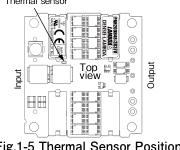
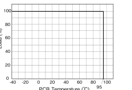
Fig.1-6 Output Derating by PCB Temperature
2 Mounting Method
(1) Mounting hole on PCB Diameter of hole and land of PCB with referring be- low.
| Type | PAH200H48 |
|---|---|
| Input Terminal Pin | φ 1.0mm |
| Hole Diameter | φ 1.5mm |
| Land Diameter | φ 3.0mm |
| Output Terminal Pin | φ 2.0mm |
| Hole Diameter | φ 2.5mm |
| Land Diameter | φ 4.5mm |
| Signal Terminal Pin | φ 1.0mm |
| Hole Diameter | φ 1.5mm |
| Land Diameter | φ 3.0mm |
For position of the holes, see outline drawing of the power module.
(2) Output Terminal Pin Connect +V, -V terminal pins such that the contact resistance becomes minimal. Note that large contact resistance could result into reduction of efficiency and abnormal temperature rise at terminal connections
(3) Output Pattern Width Large output current flows through the output pattern. If pattern is too narrow, voltage drop will occur and heat on pattern will increase. Relationship of current and the pattern width varies depending on materials of printed circuit board, conductor width, maximum allowable temperature rise of the pattern etc.. Con- firmation on manufactures of printed circuit board is definitely necessary for designing.
3 Recommended Soldering Method
(1) Soldering dip 260ºC within 6 seconds Pre-heat condition 110ºC 30 - 40 seconds (2) Soldering iron 350ºC within 3 seconds
4 Recommended Cleaning Condition
Recommended cleaning condition after soldering is as follows.
- Cleaning solvent IPA (isopropyl alcohol)
- Cleaning Procedure Use brush and dry the solvent completely. Note) For other cleaning methods, contact us.
PAH
B-223
Page 82
PAH200H
3. Before concluding power module damage
Verify following items before concluding power module damage. 1) No output voltage
- Is specified input voltage applied?
- Are the ON/OFF control terminal (CNT terminal), remote sensing terminal (+S,-S), output voltage trim- ming terminal (TRM) correctly connected?
- For cases where output voltage adjustment is used, is the resistor or variable resistor setting, connections correctly done?
- Are there no abnormalities in the output load used?
- Is the ambient temperature within the specified tem- perature derating curve?
2) Output voltage is high.
- Are the remote sensing terminals (+S, -S) correctly connected?
- Is the measurement done at the sensing points?
- For cases where output voltage adjustment is used, is the resistor or volume setting, connections cor- rectly done?
PAH
web130122 B-224
3) Output voltage is low
- Is specified input voltage applied?
- Are the remote sensing terminals (+S, -S) correctly connected?
- Is the measurement done at the sensing points?
- For cases where output voltage adjustment is used, is the resistor or variable resistor setting, connections correctly done?
- Are there no abnormalities in the output load used?
4) Load regulation and line regulation is large
- Is specified input voltage applied?
- Are the input terminals and the output terminals firmly connected?
- Is the measurement done at the sensing points?
- Is the input or output wire too thin?
5) Output ripple voltage is large
- Is the measuring method used the same or equivalent with the specified method in the Application Notes?
- Is the input ripple voltage value within the specified value?