
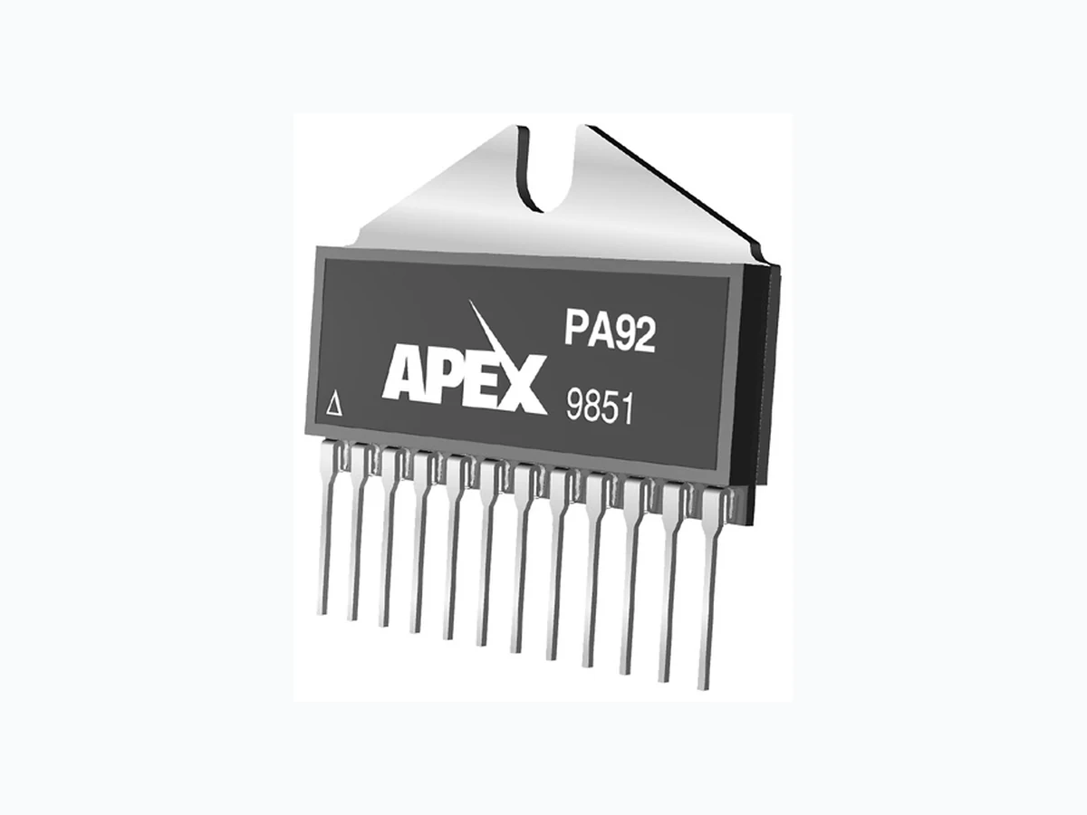
PA92_17 ETC2
Document overview
- Manufacturer or author: Provided By www.digicamel.com(FREE DATASHEET DOWNLOAD SITE)
- PDF pages: 5
Technical content
FEATURES
♦ HIGH VOLTAGE — 400V (±200V) ♦ LOW QUIESCENT CURRENT — 10mA ♦ HIGH OUTPUT CURRENT — 4A ♦ PROGRAMMABLE CURRENT LIMIT
APPLICATIONS
♦ PIEZOELECTRIC POSITIONING ♦ HIGH VOLTAGE INSTRUMENTATION ♦ ELECTROSTATIC TRANSDUCERS ♦ PROGRAMMABLE POWER SUPPLIES UP TO 390V Q1 Q2 R1 R2 C1 R3 CC1 CC2 R8 R9 Q15 R11 R12 Q16 Q12 ILIM OUT Q18 R10 Q13 Q11 +VS –IN +IN –VS IQ Q14BQ14A High Voltage Power Operational Amplifiers PA92
DESCRIPTION
The PA92 is a high voltage, low quiescent current MOSFET operational amplifier designed as a low cost solution for driving continuous output currents up to 4A and pulse currents up to 7A. The safe operating area (SOA) has no second breakdown limitations and can be observed for all type loads by choosing an appropri- ate current limiting resistor. The MOSFET output stage is biased AB for linear operation. External compensa- tion provides flexibility in choosing bandwidth and slew rate for the application. Apex Microtechnology’s Power SIP package uses a minimum of board space allowing for high density circuit boards. The Power SIP package is electrically isolated. EQUIVALENT SCHEMATIC 1 2 3 4 5 6 7 8 9 10 –IN +IN RCL +Vs –Vs TO LOAD AND FEEDBACK 11 12 Rc Cc (See IQ Reduction) * Bypassing required. IQ PATENTED 12-pin SIP PACKAGE STYLE DP Formed leads available See package style EE EXTERNAL CONNECTIONS Copyright © Apex Microtechnology, Inc. 2012 (All Rights Reserved)www.apexanalog.com MAR 2015 PA92U REVR
2 PA92U
CAUTION The PA92 is constructed from MOSFET transistors. ESD handling procedures must be observed. The exposed substrate contains beryllia (BeO). Do not crush, machine, or subject to temperatures in excess of 850°C to avoid generating toxic fumes. Parameter Test Conditions Min Typ Max Units INPUT OFFSET VOLTAGE, initial 2 10 mV OFFSET VOLTAGE vs. temperature Full temperature range 15 50 µV/°C OFFSET VOLTAGE vs. supply 10 25 µV/V OFFSET VOLTAGE vs. time 75 µV/kh BIAS CURRENT, initial 200 2000 pA BIAS CURRENT vs. supply 4 pA/V OFFSET CURRENT, initial 50 500 pA INPUT IMPEDANCE, DC 1011 Ω INPUT CAPACITANCE 4 pF COMMON MODE VOLTAGE RANGE (Note 3) ±VS Ŧ 15 V COMMON MODE REJECTION, DC VCM = ±90V 80 98 dB NOISE 100 kHz bandwidth, RS = 1 kΩ, CC = 10pF 1 µV RMS GAIN OPEN LOOP @ 15 Hz RL = 2 kΩ, CC = 10pF 94 111 dB GAIN BANDWIDTH PRODUCT @ 1 MHz RL = 2 kΩ, CC = 10pF 18 MHz POWER BANDWIDTH RL = 2 kΩ, CC = 10pF 30 kHz PHASE MARGIN Full temperature range 60 ° OUTPUT VOLTAGE SWING (Note 3) IO = 4A ±VS Ŧ 12 ±VS Ŧ 10 V CURRENT, continuous 4 A SLEW RATE, A V = 100 CC = 10pF 50 V/µs CAPACITIVE LOAD, A V = +1 Full temperature range 1 nF CHARACTERISTICS AND SPECIFICATIONS ABSOLUTE MAXIMUM RATINGS Parameter Symbol Min Max Units SUPPLY VOLTAGE, +VS to -VS 400 V OUTPUT CURRENT, source, sink, peak, within SOA 7 A POWER DISSIPATION, continuous @ TC = 25°C 80 W INPUT VOLTAGE, differential -20 20 V INPUT VOLTAGE, common mode -VS VS V TEMPERATURE, pin solder, 10s max. 260 °C TEMPERATURE, junction (Note 2) 150 °C TEMPERATURE RANGE, storage −55 125 °C OPERATING TEMPERATURE RANGE, case −40 85 °C SPECIFICATIONS
NOTES: 1. All Min/Max characteristics and specifications are guaranteed over the Specified Operating Condi- tions. Typical performance characteristics and specifications are derived from measurements taken at typical supply voltages and TC = 25°C. 2. Long term operation at the maximum junction temperature will result in reduced product life. Derate power dissipation to achieve high MTTF. 3. +V S and –VS denote the positive and negative power supply rail respectively. 4. Rating applies if the output current alternates between both output transistors at a rate faster than 60 Hz. 5. Derate max supply rating 0.625 V/°C below 25°C case. No derating needed above 25°C case. TYPICAL PERFORMANCE GRAPHS Parameter Test Conditions Min Typ Max Units SETTLING TIME to 0.1% CC = 10pF, 2V step 1 µs RESISTANCE, no load 10 Ω POWER SUPPLY VOLTAGE (Note 5) ±50 ±150 ±200 V CURRENT, quiescent 10 14 mA THERMAL RESISTANCE, AC, junction to case (Note 4) Full temp range, F > 60 Hz 1 °C/W RESISTANCE, DC, junction to case Full temp range, F < 60 Hz 1.5 °C/W RESISTANCE, junction to air Full temp range 30 °C/W TEMPERATURE RANGE, case Meets full range specifications -25 +85 °C HARMONIC DISTORTION 100 1K 10K 100k FREQUENCY F (Hz) 135 PHASE RESPONSE PHASE, Ф (°) 10 100 10K 100K FREQUENCY , F (Hz) INPUT NOISE VOLTAGE, V (nV√Hz) 100K FREQUENCY , F (Hz) –10 SMALL SIGNAL RESPONSE OPEN LOOP GAIN, A (dB) 0 3 4 OUTPUT CURRENT, IO (A) 8.0 OUTPUT VOLTAGE SWING 7. 5 7. 0 8.5 RESISTOR VALUE, RCL (/uni03A9) CURRENT LIMIT CURRENT LIMIT, ILIM (A) EXT. COMPENSATION CAPACITOR, CC (pF) SLEW RATE SLEW RATE, (V//uni03BCs) 100 300 FREQUENCY , F (Hz) DISTORTION, (%) 25 50 100 CASE TEMPERATURE, TC (°C) 1. 2 NORMALIZED QUIESCENT CURRENT NORMALIZED QUIESCENT CURRENT, IQ (X) 1. 0 0.2 0.8 INPUT NOISE VOLTAGE VOLTAGE DROP FROM SUPPL Y , VS – VO (V) 225 .001 1M 10M 270 180 125 1. 4 1. 6 6.5 .01 1M 10M CC = 150pF CC = 100pF CC = 47pF CC = 10pF CC = 150pF CC = 100pF CC = 47pF CC = 10pF 0 25 50 75 100 125 CASE TEMPERATURE, TC (°C) POWER DERATING INTERNAL POWER DISSIPATION, P (W) PO = 62W PO = 20W PO = 1W POWER RESPONSE FREQUENCY , F (Hz) OUTPUT VOLTAGE, VO (VP-P) 10K 100K 1M 100 400 CC = 10pF CC = 47pF CC = 100pF CC = 150pF 20060
4 PA92U
Please read Application Note 1 "General Operating Considerations" which covers stability, supplies, heat sinking, mounting, current limit, SOA interpretation, and specification interpretation. Visit www.apexanalog.com for Apex Microtechnology’s complete Application Notes library, Technical Seminar Workbook, and Evaluation Kits. CURRENT LIMIT For proper operation, the current limit resistor (RCL) must be connected as shown in the external connection dia- gram. For optimum reliability the resistor value should be set as high as possible. The value is calculated as fol- lows; with the maximum practical value of 16 ohms. 0.65V RCL = I LIM (A) SAFE OPERATING AREA (SOA) The MOSFET output stage of this power operational am- plifier has two distinct limitations: 1. The current handling capability of the MOSFET geom- etry and the wire bonds. 2. The junction temperature of the output MOSFETs. NOTE: The output stage is protected against transient flyback. However, for protection against sustained, high energy flyback, external fast-recovery diodes should be used. SUPPL Y TO OUTPUT DIFFERENTIAL, VS –VO (V) 10 20 30 40 80 100 200 300 500 OUTPUT CURRENT FROM +VS OR –VS, (A) .04 .08 .06 T C = 125C T C = 85C 100mS 200mS DC, TC = 25C SOA HARMONIC DISTORTION 100 1K 10K 100k FREQUENCY F (Hz) 135 PHASE RESPONSE PHASE, Ф (°) 10 100 10K 100K FREQUENCY , F (Hz) INPUT NOISE VOLTAGE, V (nV√Hz) 100K FREQUENCY , F (Hz) –10 SMALL SIGNAL RESPONSE OPEN LOOP GAIN, A (dB) 0 3 4 OUTPUT CURRENT, IO (A) 8.0 OUTPUT VOLTAGE SWING 7. 5 7. 0 8.5 RESISTOR VALUE, RCL (/uni03A9) CURRENT LIMIT CURRENT LIMIT, ILIM (A) EXT. COMPENSATION CAPACITOR, CC (pF) SLEW RATE SLEW RATE, (V//uni03BCs) 100 300 FREQUENCY , F (Hz) DISTORTION, (%) 25 50 100 CASE TEMPERATURE, TC (°C) 1. 2 NORMALIZED QUIESCENT CURRENT NORMALIZED QUIESCENT CURRENT, IQ (X) 1. 0 0.2 0.8 INPUT NOISE VOLTAGE VOLTAGE DROP FROM SUPPL Y , VS – VO (V) 225 .001 1M 10M 270 180 125 1. 4 1. 6 6.5 .01 1M 10M CC = 150pF CC = 100pF CC = 47pF CC = 10pF CC = 150pF CC = 100pF CC = 47pF CC = 10pF 0 25 50 75 100 125 CASE TEMPERATURE, TC (°C) POWER DERATING INTERNAL POWER DISSIPATION, P (W) PO = 62W PO = 20W PO = 1W POWER RESPONSE FREQUENCY , F (Hz) OUTPUT VOLTAGE, VO (VP-P) 10K 100K 1M 100 400 CC = 10pF CC = 47pF CC = 100pF CC = 150pF 20060 PHASE COMPENSATION GAIN CC* R C ≥1 150pF 100Ω ≥2 100pF 100Ω ≥3 47pF 0Ω ≥12 10pF 0Ω *CC Never to be <10pF. CC to be rated for the full supply voltage +V to -Vs. Use ceramic NPO (COG) type.
The safe operating area curves define the maximum additional internal power dissipation the amplifier can tolerate when it produces the necessary output to drive an external load. INPUT PROTECTION Although the PA92 can withstand differential voltages up to ±20V, ad- ditional external protection is recommended. Low leakage, low capaci- tance JFETs connected as diodes are recommended (e.g. 2N4416, Q1- Q4 in Figure 2). The differential input voltage will be clamped to ±1.4V. This is sufficient overdrive to produce maximum power bandwidth. POWER SUPPLY PROTECTION Unidirectional zener diode transient suppressors are recommended as protection on the supply pins. See Figure 2. The zeners clamp transients to voltages within the power supply rating and also clamp power supply reversals to ground. Whether the zeners are used or not, the system power supply should be evaluated for transient performance including power-on overshoot and power-off polarity reversals as well as line regulation. Conditions which can cause open circuits or polarity reversals on either power supply rail should be avoided or pro- tected against. Reversals or opens on the negative supply rail is known to induce input stage failure. Unidirectional transzorbs prevent this, and it is desirable that they be both electrically and physically as close to the amplifier as possible. STABILITY The PA92 is externally compensated and performance can be tailored to the application. Use the graphs of small signal response and power response as a guide. The compensation capacitor CC must be rated at 500V working voltage. An NPO capacitor is recommended. The compensation network CCRC must be mounted closely to the am- plifier pins 4 and 5 to avoid spurious oscillation. QUIESCENT CURRENT REDUCTION When pin 3 (IQ) is shorted to pin 5 (CC2) the AB biasing of the output stage is disabled. This lowers quiescent power but also raises distortion since the output stage is then class C biased. The output stage bias current is nominally set at 1mA. Pin 3 may be left open if not used. +VS –IN +IN 11, 12 7, 8 6PA90 –VS FIGURE 2. OVERVOLTAGE PROTECTION NEED TECHNICAL HELP? CONTACT APEX SUPPORT! For all Apex Microtechnology product questions and inquiries, call toll free 800-546-2739 in North America. For inquiries via email, please contact apex.support@apexanalog.com. International customers can also request support by contacting their local Apex Microtechnology Sales Representative. To find the one nearest to you, go to www.apexanalog.com IMPORTANT NOTICE Apex Microtechnology, Inc. has made every effort to insure the accuracy of the content contained in this document. However, the information is subject to change without notice and is provided "AS IS" without warranty of any kind (expressed or implied). Apex Microtechnology reserves the right to make changes without further notice to any specifications or products mentioned herein to improve reliability. This document is the property of Apex Microtechnology and by furnishing this informa- tion, Apex Microtechnology grants no license, expressed or implied under any patents, mask work rights, copyrights, trademarks, trade secrets or other intellectual property rights. Apex Microtechnology owns the copyrights associated with the information contained herein and gives consent for copies to be made of the informa- tion only for use within your organization with respect to Apex Microtechnology integrated circuits or other products of Apex Microtechnology. This consent does not extend to other copying such as copying for general distribution, advertising or promotional purposes, or for creating any work for resale. APEX MICROTECHNOLOGY PRODUCTS ARE NOT DESIGNED, AUTHORIZED OR WARRANTED TO BE SUITABLE FOR USE IN PRODUCTS USED FOR LIFE SUPPORT, AUTOMOTIVE SAFETY, SECURITY DEVICES, OR OTHER CRITICAL APPLICATIONS. PRODUCTS IN SUCH APPLICATIONS ARE UNDER- STOOD TO BE FULLY AT THE CUSTOMER OR THE CUSTOMER’S RISK. Apex Microtechnology, Apex and Apex Precision Power are trademarks of Apex Microtechnolgy, Inc. All other corporate names noted herein may be trademarks of their respective holders. Copyright © Apex Microtechnology, Inc. 2012 (All Rights Reserved)www.apexanalog.com MAR 2015 PA92U REVR