
P6SMB_V03 YAGEO
Document overview
- Manufacturer or author: Provided By digicamel.com
- PDF pages: 8
Technical content
TRANSIENT VOLTAGE SUPPRESSORS AC/DC POWER SUPPLY P6SMB series RoHS compliant & Halogen free Product specification– February 21, 2021 V.3
Transient Voltage Suppressors Circuit Protection www. yageo .com Feb. 21, 2021 V.3 Transient Voltage Suppressors (TVS) Data Sheet
Features
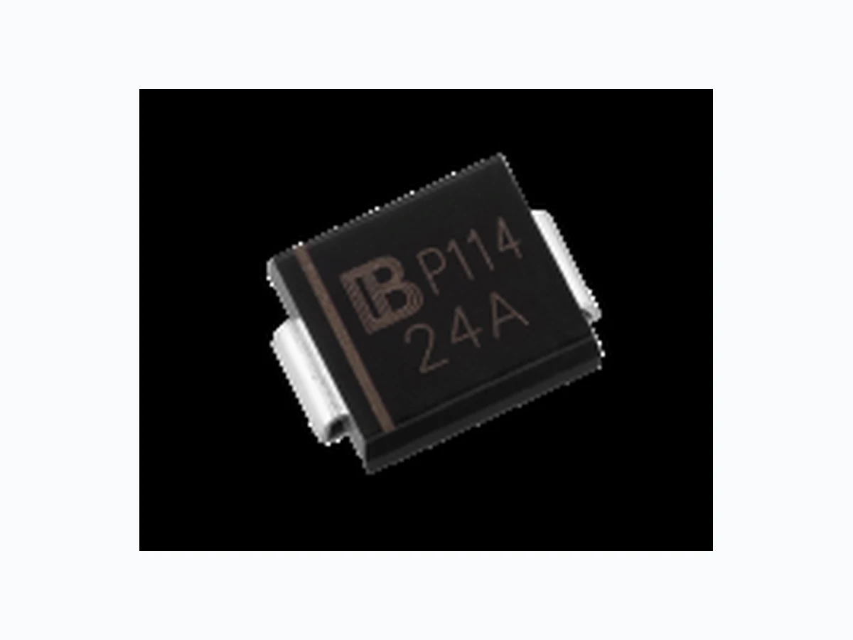
■ For surface mounted applications in order to optimize board space ■ Low profile package ■ Built-in strain relief ■ Glass passivated junction ■ Low inductance ■ Excellent clamping capability ■ 600W peak pulse power capability at 10/1000μs waveform, repetition rate (duty cycle): 0.01% ■ Fast response time ■ Typical IR less than 1μA above 12V ■ High Temperature soldering: 260℃/10 seconds at terminals ■ Plastic package has underwriters laboratory flammability 94V-0 ■ Meets MSL level 1, per J-STD-020 ■ Safety certification: UL: E244458 ■ IEC61000-4-2 ESD 30KV Air, 30KV contact compliance Mechanical Data ■ Case: JEDEC DO-214AA. Molded plastic over glass passivated junction ■ Terminal: Tin plated, solderable per MIL-STD-750, Method 2026 ■ Polarity: Color band denotes cathode except bi-directional models ■ Standard Packaging: 12mm tape (EIA STD RS-481) ■ Weight: 0.10g
Applications
■ I/O interface ■ AC/DC power supply ■ Low frequency signal transmission line (RS232, RS485, etc.) Maximum Ratings and Characteristics Ratings at 25℃ ambient temperature unless otherwise specified. Rating Symbol Value Units Peak pulse power dissipation at 10/1000μs waveform (Note1, Note2, Fig.1) PPPM Minimum 600 Watts Peak pulse current of at 10/1000μs waveform (Note 1, Fig.3) IPPM See Table Amps Steady state power dissipation at TA=50℃ (Fig.5) PM(AV) 5.0 Watts Peak forward surge current, 8.3ms single half sine-wave superimposed on rated load, (JEDEC Method) (Note3, Fig.6) IFSM 100 Amps Operating junction and Storage Temperature Range. TJ,TSTG -55 to +150 ℃ Typical thermal resistance junction to lead RθJL 20 ℃/W Typical thermal resistance junction to ambient RθJA 100 ℃/W Notes: 1. Non-repetitive current pulse, per Fig.3 and derated above TA=25℃ per Fig.2. 3. 8.3ms single half sine-wave, or equivalent square wave, duty cycle=4 pulses per minutes maximum.
Transient Voltage Suppressors Circuit Protection www. yageo .com Feb. 21, 2021 V.3 Dimensions (SMB/DO-214AA) D1 D L Cathode Band T d H Symbol Millimeters Inches Min. Max. Min. Max. L 4.06 4.57 0.160 0.180 D 3.30 3.94 0.130 0.155 D1 1.95 2.20 0.077 0.086 T 5.21 5.59 0.205 0.220 T1 0.76 1.52 0.030 0.060 d - 0.203 - 0.008 H 2.15 2.65 0.085 0.104 H1 2.13 2.47 0.084 0.097 Electrical Characteristics (TA=25℃) Part Number Device Marking Code Reverse Stand-Off Voltage Breakdown Voltage @IT Test Current Maximum Clamping Voltage @IPP Peak Pulse Current Reverse Leakage @VRWM Unidirectional Bidirectional UNI BI VRWM(V) VBR(V) IT(mA) VC(V) IPP(A) IR(μA)
Transient Voltage Suppressors Circuit Protection www. yageo .com Feb. 21, 2021 V.3 Electrical Characteristics (TA=25℃) Part Number Device Marking Code Reverse Stand-Off Voltage Breakdown Voltage @IT Test Current Maximum Clamping Voltage @IPP Peak Pulse Current Reverse Leakage @VRWM Unidirectional Bidirectional UNI BI VRWM(V) VBR(V) IT(mA) VC(V) IPP(A) IR(μA)
Figure 1. Peak Pulse Power Rating Curve
100 Peak Value IPPM
Figure 3. Pulse Waveform Figure 5. Steady State Power Dissipation Derating Figure 2. Pulse Derating Curve Figure 4. Typical Junction Capacitance Figure 6. Maximum Non-Repetitive Forward
Transient Voltage Suppressors Circuit Protection www. yageo .com Feb. 21, 2021 V.3 Recommended Soldering Conditions Reflow Soldering TP TL tS Preheat TS max TS min Ramp-up Ramp-down Critical Zone TL to TP tP tL t 25℃ to Peak Time Temperature Recommended Conditions Profile Feature Pb-Free Assembly Average ramp-up rate (TL to TP) 3℃/second max. Preheat -Temperature Min (TS min) -Temperature Max (TS max) -Time (min to max) (tS) 150℃ 200℃ 60-180 seconds TS max to TL -Ramp-up Rate 3℃/second max. Time maintained above: -Temperature (TL) -Time (tL) 217℃ 60-150 seconds Peak Temperature (TP) 260℃ Time within 5℃ of actual Peak Temperature (tP) 20-40 seconds Ramp-down Rate 6℃/second max. Time 25℃ to Peak Temperature 8 minutes max.
Transient Voltage Suppressors Circuit Protection www. yageo .com Feb. 21, 2021 V.3 Marking Code Cathode Band Internal control code Marking Code Logo A8V6 YXXX Internal control code Marking Code Logo C8V6 YXXX Part Number Code inch reel package13 :13TR inch reel package7 :7TR odeCPackage XXXX Voltage Tolerance BRV% 5 Voltage BRV Series Code Bidirectional SMB XXX C A6P Ordering Code for Different Package 7 inch reel package: Add suffix “/TR7 ” at the end of the part number,such as P6SMBXXXCA/TR7 13 inch reel package: Add suffix “/TR13 ” at the end of the part number, such as P6SMBXXXCA/TR13
Transient Voltage Suppressors Circuit Protection www. yageo .com Feb. 21, 2021 V.3 Packaging Tape P0 P1 P2 D0 E F W T B B SECTION B-B A A SECTION A-A Symbol Dimension (mm) W 12.00± 0.20 P0 4.00± 0.10 P1 8.00± 0.10 P2 2.00± 0.10 D0 Φ1.55± 0.10 D1 Φ1.5± 0.10 E 1.75± 0.10 F 5.50± 0.10 A0 3.86± 0.15 B0 5.65± 0.10 K0 2.75± 0.15 T 0.25± 0.05 7” Reel D2 Φ178.0± 2.0 D3 Φ50.0Min. D4 Φ13.0± 0.5 W1 16.0± 2.0 Quantity: 500PCS 13” Reel D5 Φ330.0± 2.0 D6 Φ13.5± 0.5 H 2.5± 1.0 W2 16.0± 2.0 Quantity: 3000PCS