
DATASHEET SEARCH SITE
Document overview
- Manufacturer or author: Provided By www.digicamel.com(FREE DATASHEET DOWNLOAD SITE)
- PDF pages: 16
Technical content
P6KE6.8 thru P6KE540A Vishay General Semiconductor Document Number: 88369 Revision: 22-Oct-08 For technical questions within your region, please contact one of the following: PDD-Americas@vishay.com , PDD-Asia@vishay.com , PDD-Europe@vishay.com www.vishay.com TRANSZORB® Transient Voltage Suppressors
FEATURES
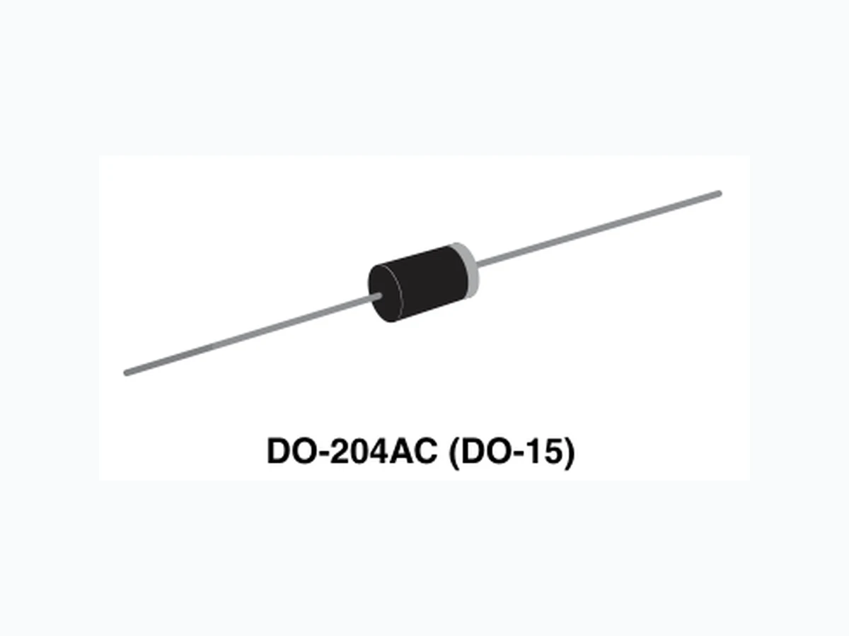
Glass passivated chip junction Available in uni-directional and bi-directional 600 W peak pulse power capability with a 10/1000 µs waveform, repetitive rate (duty cycle): 0.01 % Excellent clamping capability Very fast response time Low incremental surge resistance Solder dip 260 °C, 40 s Component in accordance to RoHS 2002/95/EC and WEEE 2002/96/EC TYPICAL APPLICATIONS Use in sensitive electronics protection against voltage transients induced by inductive load switching and lighting on ICs, MOSFET, signal lines of sensor units for consumer, computer, industrial, automotive and telecommunication. MECHANICAL DATA Case: DO-204AC, molded epoxy over passivated chip Molding compound meets UL 94 V-0 flammability rating Base P/N-E3 - RoHS compliant, commercial grade Base P/NHE3 - RoHS co mpliant, high reliability/ automotive grade (AEC Q101 qualified) Terminals: Matte tin plated leads, solderable per J-STD-002 and JESD22-B102 E3 suffix meets JESD 201 class 1A whisker test, HE3 suffix meets JESD 201 class 2 whisker test Note: P6KE250 ~ P6KE540A and P6KE250C ~ P6KE440CA for commercial grade only Polarity: For uni-directional types the color band denotes cathode end, no marking on bi-directional types DEVICES FOR BI-DIRECTION APPLICATIONS For bi-directional types, use C or CA suffix (e.g. P6KE440CA). Electrical characteristics apply in both directions. PRIMARY CHARACTERISTICS VBR uni-directional 6.8 V to 540 V VBR bi-directional 6.8 V to 440 V PPPM 600 W PD 5.0 W IFSM (uni-directional only) 100 A TJ max. 175 °C DO-204AC (DO-15) Notes: (1) Non-repetitive current pulse, per Fig. 3 and derated above TA = 25 °C per Fig. 2 (2) Measured on 8.3 ms single half sine-wave or equivalent square wave, duty cycle = 4 per minute maximum (3) VF = 3.5 V for P6KE220(A) and below; VF = 5.0 V for P6KE250(A) and above MAXIMUM RATINGS (TA = 25 °C unless otherwise noted) PARAMETER SYMBOL VALUE UNIT Peak power dissipation with a 10/1000 µs waveform (1) (Fig. 1) P PPM 600 W Peak pulse current with a 10/1000 µs waveform (1) IPPM See next table A Power dissipation on infinite heatsink at TL = 75 °C (Fig. 5) P D 5.0 W Peak forward surge current, 8.3 ms single half sine-wave (2) IFSM 100 A Maximum instantaneous forward voltage at 50 A for uni-directional only (3) VF 3.5/5.0 V Operating junction and storage temperature range T J, TSTG - 55 to + 175 °C
P6KE6.8 thru P6KE540A Vishay General Semiconductor www.vishay.com For technical questions within your region, please contact one of the following: PDD-Americas@vishay.com , PDD-Asia@vishay.com , PDD-Europe@vishay.com Document Number: 88369 Revision: 22-Oct-082 ELECTRICAL CHARACTERISTICS (TA = 25 °C unless otherwise noted) DEVICE TYPE BREAKDOWN VOLTAGE VBR AT IT (1) (V) TEST CURRENT IT (mA) STAND-OFF VOLTAGE VWM (V) MAXIMUM REVERSE LEAKAGE AT VWM (3) ID (µA) PEAK PULSE CURRENT IPPM (2) (A) MAXIMUM CLAMPING VOLTAGE AT IPPM VC (V) MAXIMUM TEMPERATURE COEFFICIENT OF VBR (%/°C) MIN. MAX.
P6KE6.8 thru P6KE540A Vishay General Semiconductor Document Number: 88369 Revision: 22-Oct-08 For technical questions within your region, please contact one of the following: PDD-Americas@vishay.com , PDD-Asia@vishay.com , PDD-Europe@vishay.com www.vishay.com (+)P6KE120A 114 126 1.0 102 1.0 3.6 165 0.107 (+)P6KE130 117 143 1.0 105 1.0 3.2 187 0.107 (+)P6KE130A 124 137 1.0 111 1.0 3.4 179 0.107 (+)P6KE150 135 165 1.0 121 1.0 2.8 215 0.108 (+)P6KE150A 143 158 1.0 128 1.0 2.9 207 0.108 (+)P6KE160 144 176 1.0 130 1.0 2.6 230 0.108 (+)P6KE160A 152 168 1.0 136 1.0 2.7 219 0.108 (+)P6KE170 153 187 1.0 138 1.0 2.5 244 0.108 (+)P6KE170A 162 179 1.0 145 1.0 2.6 234 0.108 (+)P6KE180 162 198 1.0 146 1.0 2.3 258 0.108 (+)P6KE180A 171 189 1.0 154 1.0 2.4 246 0.108 (+)P6KE200 180 220 1.0 162 1.0 2.1 287 0.108 (+)P6KE200A 190 210 1.0 171 1.0 2.2 274 0.108 (+)P6KE220 198 242 1.0 175 1.0 1.7 344 0.108 (+)P6KE220A 209 231 1.0 185 1.0 1.8 328 0.108 (+)P6KE250 225 275 1.0 202 1.0 1.7 360 0.110 (+)P6KE250A 237 263 1.0 214 1.0 1.7 344 0.110 (+)P6KE300 270 330 1.0 243 1.0 1.4 430 0.110 (+)P6KE300A 285 315 1.0 256 1.0 1.4 414 0.110 (+)P6KE350 315 385 1.0 284 1.0 1.2 504 0.110 (+)P6KE350A 333 368 1.0 300 1.0 1.2 482 0.110 (+)P6KE400 360 440 1.0 324 1.0 1.0 574 0.110 (+)P6KE400A 380 420 1.0 342 1.0 1.1 548 0.110 ELECTRICAL CHARACTERISTICS (TA = 25 °C unless otherwise noted) DEVICE TYPE BREAKDOWN VOLTAGE VBR AT IT (1) (V) TEST CURRENT IT (mA) STAND-OFF VOLTAGE VWM (V) MAXIMUM REVERSE LEAKAGE AT VWM (3) ID (µA) PEAK PULSE CURRENT IPPM (2) (A) MAXIMUM CLAMPING VOLTAGE AT IPPM VC (V) MAXIMUM TEMPERATURE COEFFICIENT OF VBR (%/°C) MIN. MAX.
P6KE6.8 thru P6KE540A Vishay General Semiconductor www.vishay.com For technical questions within your region, please contact one of the following: PDD-Americas@vishay.com , PDD-Asia@vishay.com , PDD-Europe@vishay.com Document Number: 88369 Revision: 22-Oct-084 Notes: (1) Pulse test: tp ≤ 50 ms (2) Surge current waveform per Fig. 3 and derate per Fig. 2ogm (3) For bi-directional types with VWM of 10 V and less, the ID limit is doubled (4) All terms and symbols are consistent with ANSI/IEEE C62.35 (+) Underwriters laboratory recognition for the classification of protectors (QVGQ2) under the UL standard for safety 497B and file number E136766 for both uni-directional and bi-directional devices Note: (1) Automotive grade AEC-Q101 qualified (+)P6KE440 396 484 1.0 356 1.0 0.95 631 0.110 (+)P6KE440A 418 462 1.0 376 1.0 1.00 602 0.110 P6KE480 432 528 1.0 389 1.0 0.88 686 0.110 P6KE480A 456 504 1.0 408 1.0 0.91 658 0.110 P6KE510 459 561 1.0 413 1.0 0.82 729 0.110 P6KE510A 485 535 1.0 434 1.0 0.86 698 0.110 P6KE540 486 594 1.0 437 1.0 0.78 772 0.110 P6KE540A 513 567 1.0 459 1.0 0.81 740 0.110 ELECTRICAL CHARACTERISTICS (TA = 25 °C unless otherwise noted) DEVICE TYPE BREAKDOWN VOLTAGE VBR AT IT (1) (V) TEST CURRENT IT (mA) STAND-OFF VOLTAGE VWM (V) MAXIMUM REVERSE LEAKAGE AT VWM (3) ID (µA) PEAK PULSE CURRENT IPPM (2) (A) MAXIMUM CLAMPING VOLTAGE AT IPPM VC (V) MAXIMUM TEMPERATURE COEFFICIENT OF VBR (%/°C) MIN. MAX. THERMAL CHARACTERISTICS (TA = 25 °C unless otherwise noted) PARAMETER SYMBOL VALUE UNIT Typical thermal resistance, junction to lead R θJL 20 °C/W Typical thermal resistance, junction to ambient R θJA 75 °C/W ORDERING INFORMATION (Example) PREFERRED P/N UNIT WEIGHT (g) PREFERRED PACKAGE CODE BASE QUANTITY DELIVERY MODE P6KE6.8A-E3/54 0.432 54 4000 13" diameter paper tape and reel P6KE6.8AHE3/54 (1) 0.432 54 4000 13" diameter paper tape and reel
at a maximum peak pulse current is specified. specification insignificant. entire circuit. Curves depicting clamping voltage vs. various current pulses are available from the factory. Figure 7. Typical Transient Thermal Impedance
www.vishay.com Vishay Revision: 12-Mar-12 1 Document Number: 91000 Disclaimer ALL PRODUCT, PRODUCT SPECIFICATIONS AND DATA ARE SUBJECT TO CHANGE WITHOUT NOTICE TO IMPROVE RELIABILITY, FUNCTION OR DESIGN OR OTHERWISE. Vishay Intertechnology, Inc., its affiliates, agents, and employee s, and all persons acting on it s or their behalf (collectivel y, “Vishay”), disclaim any and all liability for any errors, inaccuracies or incompleteness contained in any datasheet or in any other disclosure relating to any product. Vishay makes no warranty, repres entation or guarantee regarding the suitabilit y of the products for any particular purpose or the continuing production of any product. To the maximum extent permitted by applicable law, Vishay disclaims (i) any and all liability arising out of the application or use of any product, (ii) any and all liability, including without limitation specia l, consequential or incidental damages, and (iii) any and all i mplied warranties, including warra nties of fitness for particular purpose, non-infringement and merchantability. Statements regarding the suitability of products for certain type s of applications are based on Vishay’s knowledge of typical requirements that are often placed on Vishay products in generic applications. Such statements are not binding statements about the suitability of products for a particular application. It is the customer’s responsib ility to validate that a particu lar product with the properties descri bed in the product specification is suitable fo r use in a particular application. Parameters provided in datasheets and/or specification s may vary in different applications an d performance may vary over time. All operating parameters, including typical pa rameters, must be validated for each customer application by the customer’s technical experts. Product specifications do not expand or otherwise modify Vish ay’s terms and condit ions of purchase, including but not limited to the warranty expressed therein. Except as expressly indicate d in writing, Vishay products are not designed for use in medical, life-saving, or life-sustaining applications or for any other application in which the failure of the Vi shay product could result in personal injury or death. Customers using or selling Vishay products not expressly indicated for use in such applications do so at their own risk and agree to fully indemnify and hold Vishay and it s distributors harmless from and against an y and all claims, liabilities, expenses and damages arising or resulting in connection with such use or sale, including attorneys fees, even if such claim alleges that Vishay or its distributor was negligent regarding the design or manufacture of the part. Please contact authorized Vishay personnel to obtain written terms and conditions regarding products designed for such applications. No license, express or implied, by estoppel or otherwise, to any intellectual prope rty rights is granted by this document or by any conduct of Vishay. Product names and markings noted herein may be trademarks of their respective owners. Material Category Policy Vishay Intertechnology, Inc. hereby certi fies that all its products that are id entified as RoHS-Compliant fulfill the definitions and restrictions defined under Directive 2011/65/EU of The Euro pean Parliament and of the Council of June 8, 2011 on the restriction of the use of certain hazardous substances in electrical and electronic equipment (EEE) - recast, unless otherwise specified as non-compliant. Please note that some Vishay documentation may still make reference to RoHS Directive 2002/95/EC. We confirm that all the products identified as being compliant to Directive 2002/95/EC conform to Directive 2011/65/EU.
www.vishay.com Vishay General Semiconductor Revision: 01-Feb-13 1 Document Number: 88869 For technical questions within your region: DiodesAmericas@vishay.com, DiodesAsia@vishay.com, DiodesEurope@vishay.com THIS DOCUMENT IS SUBJECT TO CHANGE WITHOUT NOTICE. THE PRODUCTS DESCRIBED HEREIN AND THIS DOCUMENT ARE SUBJECT TO SPECIFIC DISCLAIMERS, SET FORTH AT www.vishay.com/doc?91000 Packaging Information Notes (1) Formerly sold by Vishay Telefunken® (Telefunken® is a registered trademark of Electro Holding GmbH).
- “P” and bold letter denote s preferred package code.
- A “T” suffix added to the packaging codes for SMA, SMB and SMC products indicates that the patented folded-frame construction is used. This does not apply to TR and TR3 codes or TRANSZORB® TVS in SMA and SMB. PACKAGING ORDERING CODE ANTI-STATIC PACKAGE CODE PREFERRED PACKAGE CODE PACKAGING DESCRIPTION
51 Bulk
52, 52T P DO-214AA (SMB)/DO-215AA (SMBG), 12 mm tape, 7" diameter plastic reel 2D P DO-218AB (SM5-8A), 24 mm tape, 13" diameter plastic reel, anode towards sprocket hole 2E DO-218AB (SM5-8A), 24 mm tape, 13" diameter plastic reel, cathode towards sprocket hole 2M Tube packaging for 5KP/6KA type lead formed components 2N DO-218AB, 24 mm tape, 13 "diameter plastic reel with dry packaging, anode towards sprocket hole 53 26 mm horizontal taping and ammo box packaging 54 P 52.4 mm horizontal tape , 13" diameter paper reel 5A, 5AT P DO-214AC (SMA), 12 mm ta pe, 13" diameter plastic reel 5B, 5BT P DO-214AA (SMB)/DO-215AA (SMBG), 12 mm tape, 13" diameter plastic reel 5CA P DO-214BA (GF1), 12 mm tape , 13" diameter plastic reel 57, 57T P DO-214AB (SMC)/DO-215A B (SMCG), 16 mm tape, 7" diameter plastic reel 6A P DO-221AC (SlimSMA), 12 mm tape, 7"diameter plastic reel 6B P DO-221AC (SlimSMA), 12 mm ta pe, 13"diameter plastic reel 9A, 9AT P DO-214AB (SMC)/DO- 215AB (SMCG), 16 mm tape, 13" diameter plastic reel 61, 61T P DO-214AC (SMA), 12 mm tape, 7" diameter plastic reel 67A P DO-214BA (GF1), 12 mm tape, 7" diameter plastic reel
72 P Bulk pack for bridge and special axial-leaded formed devices
73 52.4 mm horizontal tape and ammo box packaging
77 P DFS bridge, 16 mm tape, 13" diameter paper reel
80 P TO-269AA (MB-S) bridge, 12 mm ta pe, 13" diameter paper reel
81 P TO-263AB 24 mm tape, 13" diameter reinforced hub plastic reel
8A P SMPD, 24 mm tape, 13" diameter plastic reel 8W P TO-263AB (wire bond) 24 mm tape, 13" diameter reinforced hub plastic reel
83 P DO-213AA (GL34) 8 mm tape, 13" diameter plastic reel
84A P DO-220AA (SMP) 12 mm tape, 7" diameter plastic reel 85A P DO-220AA (SMP) 12 mm tape, 13" diameter plastic reel 86A P TO-277A (SMPC), 12 mm tape , 7" diameter plastic reel 87A P TO-277A (SMPC), 12 mm tape , 13" diameter plastic reel
38 Lead forming bulk packaging in anti-static bags
89A P MicroSMP, 8 mm tape, 7" diameter plastic reel
90 Euroform, reel, cathode first off reel, lead coated
91 Euroform, ammo pack, cathode first out of ammo pack, lead coated
92 Euroform, reel, cathode last off reel, lead coated
93 Euroform, ammo pack, cathode last out of ammo pack, lead coated
45 P Anti-static tube packaging for Bridge and Power Pack
4W P Anti-static tube packaging for wire bond TO-220, ITO-220, TO-262 and TO-263
96 P DO-213AB (GL41), 12 mm tape, 7" diameter plastic reel
97 P DO-213AB (GL41), 12 mm tape, 13" diameter plastic reel
98 P DO-213AA (GL34), 8 mm tape, 7" diameter plastic reel
100 MPG06 pseudo radial tape, cath ode first out of ammo pack
H P Tape in 7" diameter plastic reel I P Tape in 13" diameter plastic reel TR P DO-214AC (SMA), 12 mm tape, 7" diameter plastic reel (1) TR3 P DO-214AC (SMA), 12 mm tape, 13" diameter plastic reel (1)
www.vishay.com Vishay General Semiconductor Revision: 01-Feb-13 2 Document Number: 88869 For technical questions within your region: DiodesAmericas@vishay.com, DiodesAsia@vishay.com, DiodesEurope@vishay.com THIS DOCUMENT IS SUBJECT TO CHANGE WITHOUT NOTICE. THE PRODUCTS DESCRIBED HEREIN AND THIS DOCUMENT ARE SUBJECT TO SPECIFIC DISCLAIMERS, SET FORTH AT www.vishay.com/doc?91000 BULK PACKAGING CASE TYPES PREFERRED PACKAGE CODE PACKAGING BOX SIZE QUANTITY INCHES cm EA. DF-M, DF-S, DFL-S 45 Anti-static plasti c tubes 17.4 length 44.1 length 50 GSIB-3S 45 Anti-static plastic tu bes 25.1 length 63.9 length 20 GSIB-5S, PB 45 Anti-static plastic tubes 24.2 length 61.5 length 20 GBU, BU 45 Anti-static plastic tu bes 18.5 length 47 length 20 GBL 45 Anti-static plastic tube s 17.5 length 44.5 length 20 KBPM 45 Anti-static plastic tu bes 18.5 length 47 length 30 TO-220AB/AC, ITO-220AC/AB, TO-262AA 45, 4W Anti-sta tic plastic tubes 21.0 length 53.7 length 50 TO-247AD 45 Anti-static plastic tu bes 20.0 length 50.8 length 30 TO-269AA (MB-S) 45 Anti-static plas tic tubes 20.3 x 0.41 51.5 x 1.04 100 WOG, 2WOG 51 Plastic bags - - 100
www.vishay.com Vishay General Semiconductor Revision: 01-Feb-13 3 Document Number: 88869 For technical questions within your region: DiodesAmericas@vishay.com, DiodesAsia@vishay.com, DiodesEurope@vishay.com THIS DOCUMENT IS SUBJECT TO CHANGE WITHOUT NOTICE. THE PRODUCTS DESCRIBED HEREIN AND THIS DOCUMENT ARE SUBJECT TO SPECIFIC DISCLAIMERS, SET FORTH AT www.vishay.com/doc?91000 AXIAL-LEADED TAPE AND REEL PACKAGING All axial-leaded devices are packed in accordance with EIA standard RS-296-E. The diagrams given below refer to these specifications. Fig. 1 Fig. 2 TABLE 1 - AMMO PACK PACKAGING PACKAGING AVAILABLE PRODUCT OUTLINES PREFERRED PACKAGE CODE DIMENSION A DIMENSION B DIMENSION C QUANTITY BOX 26 mm horizontal tape, ammo pack DO-204AL (DO-41), MPG06 DO-204AC P300 9.7" (247 mm) 1.7" (44 mm) 3.7" (95 mm) 3.0K 1.5K 0.75K 52 mm horizontal tape, ammo pack DO-204AL, MPG06 DO-204AC DO201AD, GP20 P600 10.0" (255 mm) 3.15" (80 mm) 4.53" (115 mm) 3.0K 2.0K 1.0K 0.3K Radial (avisert, panasert, euroform) vertical tape GP10-E, RGP10-E, GP10-E, RGP10-E 91, 93 13.4" (340 mm) 1.8" (47 mm) 7.9" (200 mm) 2.0K 2.5K 2.0K Pseudo/radial tape, ammo pack MPG06 100 13.4" (340 mm) 1.8" (47 mm) 7.9" (200 mm) 2.0K A C B Inspection Hole (Both Sides) Ammo Pack can be Opened on Either Side, Depending on Desired Device Polarity Component Pitch A 2, 3 Inside Tape Spacing B 2, 3 Lead to Lead Eccentricity |D1 - D2| - Lead Extension K - Lead Bending E 2 Cumulative Pitch P 3 Exposed Adhesive S - Tape Width T - All polarized components shall be oriented in the same direction Description Symbol E D1 D2 A P K S B W 0.8 (0.031) Max. Dimensions A, M, K, P , S and T apply to both sides Dimensions in millimeters (inches) E T6.0 ± 0.4 (0.236 ± 0.0157) The “C” dimension of Fig. 2 is between flanges of the component reel and shall be 1.5 mm (0.059") to 8.00 mm (0.315") greater than the overall taped component width “W” (Fig. 1). Where “W” dimension is 68.2 mm (2.68") max. 38.1 (1.50) Dia. 14.3 (0.56) Dia. D Dia. (Table 2) Kraft Paper 91.9 (3.62) Dia. 50.8 (2.00) Dia. Cathode Lead Colored Tape C Anode Lead White Tape
www.vishay.com Vishay General Semiconductor Revision: 01-Feb-13 4 Document Number: 88869 For technical questions within your region: DiodesAmericas@vishay.com, DiodesAsia@vishay.com, DiodesEurope@vishay.com THIS DOCUMENT IS SUBJECT TO CHANGE WITHOUT NOTICE. THE PRODUCTS DESCRIBED HEREIN AND THIS DOCUMENT ARE SUBJECT TO SPECIFIC DISCLAIMERS, SET FORTH AT www.vishay.com/doc?91000 AXIAL-LEADED TAPE AND REEL PACKAGING Note
- Package codes, 61/5A, 52/5B are matrix-frame constructions for T RANSZORB® TVS in SMA and SMB only. TABLE 2 - REEL AND AMMO PACK TAPING SPECIFICATIONS COMPONENT CASE TYPE PREFERRED PACKAGE CODE UNITS PER REEL COMPONENT PITCH “A” Fig. 1 INSIDE TAPE SPACING “B” Fig. 1 REEL DIMENSION “D” Fig. 2 LEAD BENDING “E” Fig. 1 EA. INCHES mm INCHES mm INCHES mm INCHES mm DFS Surface Mount 77 1500 Fig. 13 - - 13.0 330 Fig. 13 - DO-214BA (GF1) 67A/5CA 1500/6500 - - 7.0/13.0 178/330 Fig. 13 - DO-213AA (GL34) 98/83 2500/9000 - - 7.0/13.0 178/330 Fig. 13 - DO-213AB (GL41) 96/97 1500/5000 - - 7.0/13.0 178/330 Fig. 13 - DO-220AA (SMP) 84A/85A 3000/10 000 Fig. 13 SMPD 8A 2000 - - 13.0 330 Fig. 13 - MicroSMP 89A 4500 - - 7.0 178 Fig. 13 - TO-277A (SMPC) 86A/87A 1500/6500 - - 7.0/13.0 178/330 Fig. 13 - DO-214AC (SMA) 61, 61T, TR/5A, 5AT, TR3 1800/7500 - - 7.0/13.0 178/330 Fig. 13 - DO-214AA (SMB)/ DO-215AA (SMBG) 52, 52T/5B, 5BT 750/3200 - - 7.0/13.0 178/330 Fig. 13 - DO-214AB (SMC)/ DO-215AB (SMCG) 57T/9AT 850/3500 - - 7.0/13.0 178/330 Fig. 13 - DO-218AB 2D 750 - - 13.0 330 Fig. 13 - TO-263AB 81, 8W 800 - - 13.0 330 Fig. 13 - TO-269AA (MB-S) 80 3000 - - 13.0 330 Fig. 13 - DO-221AC (SlimSMA) 6A/6B 3500/14 000 - - 7.0/13.0 178/330 Fig. 13 - TABLE 3 - COMPONENT AND INSIDE HORIZONTAL TAPE SPACING COMPONENT BODY DIAMETER COMPONENTS SPACING A (LEAD TO LEAD) INSIDE TAPE SPACING "B" CUMULATIVE PITCH TOLERANCE 0 mm to 5 mm (0.0" to 0.197") 5.0 mm ± 0.5 mm (0.197" ± 0.020") 26 mm + 1.5 mm/- 0.0 mm Not to exceed 1.5 mm (0.059") over 6 consecutive components 0 mm to 5 mm (0.0" to 0.197") 5.0 mm ± 0.5 mm (0.197" ± 0.020") 52.4 mm + 1.5 mm/- 0.4 mm 5.01 mm to 10 mm (0.197" to 0.394") 10 mm ± 0.5 mm (0.394" ± 0.020") 52.4 mm + 1.5 mm/- 0.4 mm
www.vishay.com Vishay General Semiconductor Revision: 01-Feb-13 5 Document Number: 88869 For technical questions within your region: DiodesAmericas@vishay.com, DiodesAsia@vishay.com, DiodesEurope@vishay.com THIS DOCUMENT IS SUBJECT TO CHANGE WITHOUT NOTICE. THE PRODUCTS DESCRIBED HEREIN AND THIS DOCUMENT ARE SUBJECT TO SPECIFIC DISCLAIMERS, SET FORTH AT www.vishay.com/doc?91000 DIMENSIONS in millimeters (inches) Fig. 3 - Euroform Fig. 4 - Panasert Available for GP10 Products only Utilizing 0.65 mm (0.025") Diameter Leads for Euroform tape by adding suffix “E” (GP10GE, 1N4004GPE). Lead coating is standard. Tape 5.68 (0.224) 4.68 (0.184) (Center to Center) 20.5 18.5 (0.807) (0.728) 11.0 MAX. (0.433) 4.55 (0.179) 3.15 (0.124) (Center to Center) 1.0 MAX. (2) (0.40) (Center to Center) 6.5 MAX. (0.256) 16.5 (0.650) 15.5 (0.610) 4.3 (0.169) 3.7 (0.146) DIA. 2.5 MIN. (0.098) 12.0 MAX. (0.472) 7.35 (0.29) 5.35 (0.21) 0.6 MAX. (0.024) 9.75 (0.384) 8.50 (0.335) 19.0 (0.748) 17.5 (0.689) 13.5 (0.531) 12.5 (0.492) User Direction Feed 32.0 (1.26) 23.0 (0.905) 2.72 (0.107) 2.03 (0.080) Body DIA. 0.65 (0.0256) 0.55 (0.022) Lead DIA. ± 1.0 (2) (± 0.039) 0.6 (0.025) 0.4 (0.016) 13.0 (0.512) 12.4 (0.488) 12.7 (0.50) (Nominal) A (1) B (1) Note: (1) Measurement difference between leads, A and B = 0.4 (0.016) MAX. (2) Component Alignment Tape 19.0 (0.748) 17.5 (0.689) 9.75 (0.384) 8.50 (0.335) User Direction Feed 16.0 MIN. (0.630) 32.0 (1.26) 23.0 (0.905) 5.5 MIN. (0.217) (Center to Center) 6.5 MAX. (0.256) 4.3 (0.169) 3.7 (0.146) DIA. 5.68 (0.224) 4.68 (0.184) (Center to Center) 16.5 (0.650) 15.5 (0.610) 1.0 MAX. (1) (0.40) 7.0 MIN. (0.276) 1.3 MIN. (0.059) 2.72 (0.107) 2.03 (0.080) Body DIA. 0.86 (0.034) 0.55 (0.022) Lead DIA. ± 1.0 (1) (± 0.039) 0.6 (0.025) 0.4 (0.016) 13.0 (0.512) 12.4 (0.488) 11.0 MAX. (0.433) 4.55 (0.179) 3.15 (0.124) (Center to Center) 12.7 (0.50) (Nominal) Note: (1) Component Alignment
www.vishay.com Vishay General Semiconductor Revision: 01-Feb-13 6 Document Number: 88869 For technical questions within your region: DiodesAmericas@vishay.com, DiodesAsia@vishay.com, DiodesEurope@vishay.com THIS DOCUMENT IS SUBJECT TO CHANGE WITHOUT NOTICE. THE PRODUCTS DESCRIBED HEREIN AND THIS DOCUMENT ARE SUBJECT TO SPECIFIC DISCLAIMERS, SET FORTH AT www.vishay.com/doc?91000 DIMENSIONS in millimeters (inches) Fig. 5 - Avisert Fig. 6 - Pseudo Radial Note: (1) Component Alignment Available only for GP10 style products utilizing 0.65 mm (0.025") or 0.76 mm (0.030") diameter leads for Panasert and Avisert tape. Lead coating is available on GP10 products only. User Direction Feed13.0 (0.512) 12.4 (0.488) 6.5 MAX. (0.256) 5.68 (0.224) 4.68 (0.184) (Center to Center) (Center to Center) 1.0 MAX. (1) (0.40) 16.5 (0.650) 15.5 (0.610) 4.55 (0.179) 3.15 (0.124) (Center to Center) 4.3 (0.169) 3.7 (0.146) 2.72 (0.107) 2.03 (0.080) Body DIA. 0.86 (0.034) 0.55 (0.022) Lead DIA. ± 1.0 (1) (± 0.039) 3.0 MAX. (0.118) 0.6 (0.025) 0.4 (0.016) 16.0 MIN. (0.630) 32.0 (1.26) 23.0 (0.905) 5.5 MIN. (0.217) Tape 19.0 (0.748) 17.5 (0.689) 9.75 (0.384) 8.50 (0.335) 11.0 MAX. (0.433) 12.7 (0.50) (Nominal) Standard Polarity Cathode Oriented Away from Sprocket Holes (Optional Polarity Cathode Oriented Toward Sprocket Holes) 16.0 (0.63) MIN. 2.0 (0.079) MAX. 11.0 (4.33) MAX. 13.0 (0.51) 12.4 (0.49) 4.3 (0.169) 3.7 (0.146) DIA. 12.5 (0.492) MIN. Tape 19.0 (0.748) 17.5 (0.689) 9.75 (0.384) 8.50 (0.335) ± 1.0 (1) (± 0.039) 1.0 (0.039) MAX. 0.6 (0.025) 0.4 (0.016) Available only for MPG06 Product in Ammo Pack in Accordance with EIA Standard RS-468-A Utilizing User Direction Feed 0.66 (0.026) 0.55 (0.022) Lead DIA. 2.54 (0.01) 2.29 (0.090) Body DIA.3.2 (0.125) 2.9 (0.115) 3.06 (0.118) MAX. 5.68 (0.224) 4.68 (0.184) 4.51 (0.178) 3.11 (0.122) (Center to Center) 12.7 (0.50) (Nominal) 1.0 MAX. (1) (0.40) Note: (1) Component Alignment
www.vishay.com Vishay General Semiconductor Revision: 01-Feb-13 7 Document Number: 88869 For technical questions within your region: DiodesAmericas@vishay.com, DiodesAsia@vishay.com, DiodesEurope@vishay.com THIS DOCUMENT IS SUBJECT TO CHANGE WITHOUT NOTICE. THE PRODUCTS DESCRIBED HEREIN AND THIS DOCUMENT ARE SUBJECT TO SPECIFIC DISCLAIMERS, SET FORTH AT www.vishay.com/doc?91000 RADIAL TAPE PACKAGING Fig. 7 and Fig. 8 - Reel and Ammo Box Packaging Fig. 9 - Reel Dimensions Notes
- “C” dimension between the reel flanges shal l be governed by the overall width of the taped components and shall be 1.5 mm (0. 057") to 8.0 mm (0.315") greater than the overall width
- All leaded devices are pa ckaged in accordance with EIA standard RS-468-A specification and are available on reel or in fan fold box (ammo pack)
- All dimensions are in millimeters and (inches). The above packaging is only available from Taiwan. PKG90 PKG92 PKG91 PKG93 PREFERRED PACKAGE CODE EUROFORM PKG90, PKG91, PKG92, PKG93 Core DIA. 34.9 to 102 (1.37 to 4.02) “C” Arbor Hole DIA. 30 ± 5 ID (1.181 ± 0.197)
www.vishay.com Vishay General Semiconductor Revision: 01-Feb-13 8 Document Number: 88869 For technical questions within your region: DiodesAmericas@vishay.com, DiodesAsia@vishay.com, DiodesEurope@vishay.com THIS DOCUMENT IS SUBJECT TO CHANGE WITHOUT NOTICE. THE PRODUCTS DESCRIBED HEREIN AND THIS DOCUMENT ARE SUBJECT TO SPECIFIC DISCLAIMERS, SET FORTH AT www.vishay.com/doc?91000 SURFACE MOUNT TAPE AND REEL PACKAGING Fig. 10 Fig. 11 Fig. 12 Component Cavity Embossed Carrier Tape Top Cover Tape Thickness: 0.10 mm (0.004") Max. R Ref. Bending Radius Tape with Components shall Pass Around Bending Radius without Damage, for Reels with Hub Diameters Approaching Minimum Dimension B N A T D C G DIMENSIONS in millimeters (inches) TAPE SIZE A MAX. B MIN. C D MIN. N MIN. G MAX. T MAX.
www.vishay.com Vishay General Semiconductor Revision: 01-Feb-13 9 Document Number: 88869 For technical questions within your region: DiodesAmericas@vishay.com, DiodesAsia@vishay.com, DiodesEurope@vishay.com THIS DOCUMENT IS SUBJECT TO CHANGE WITHOUT NOTICE. THE PRODUCTS DESCRIBED HEREIN AND THIS DOCUMENT ARE SUBJECT TO SPECIFIC DISCLAIMERS, SET FORTH AT www.vishay.com/doc?91000 SURFACE MOUNT TAPE AND REEL PACKAGING Fig. 13 Notes (1) A0, B0, and K0 are determined by the maximum dimensions of the component size. The clearance between the component and the cavity (2) All surface mount components are packed in accordance with EIA standard 481-C 8 mm, 12 mm, 16 mm, AND 24 mm EMBOSSED TAPE in millimeters (inches) TAPE SIZE D 0 E1 P0 P2 A0, B0, K0 S1 MIN. T MAX. T 1 MAX. 8 mm, 12 mm 1.5 ± 0.1 (0.059 ± 0.004) 1.75 ± 0.1 (0.069 ± 0.004) 4.0 ± 0.1 (0.157 ± 0.004) 2.0 ± 0.05 (0.024) 0.600 (0.024) 0.1 (0.004)16 mm, 24 mm 2.0 ± 0.1 (0.79 ± 0.004) DIMENSIONS in millimeters (inches) CASE TYPE TAPE DO-213AA (GL34) 8 (0.315) 4.2 (0.165) 1.0 (0.39) 6.25 (0.246) 3.5 ± 0.05 (0.138 ± 0.002) 4.0 ± 0.10 (0.57 ± 0.004) (0.984) 2.4 (0.094) 8.0 ± 0.30 (0.315 ± 0.012)MicroSMP 3.28 (0.129) 6.05 (0.238) 1.919 (0.076) DO-213AB (GL41) (0.472) 8.2 (0.323) 1.5 (0.059) 10.25 (0.404) 5.5 ± 0.05 (0.217 ± 0.002) (1.181) 4.5 (0.177) 12.0 ± 0.30 (0.472 ± 0.012) DO-214BA (GF1) 3.25 (0.128) DO-214AC(SMA) 2.64 (0.104) DO-220AA (SMP) 1.84 (0.072) TO-277A (SMPC) 7.0 (2.76) 8.0 ± 0.10 (0.315 ± 0.004) 1.43 (0.056) DO-214AA (SMB)/ DO-215AA (SMBG) 8.2 (0.323) 2.77 (0.109) DO-214AB (SMC)/ DO-215AB (SMCG) 16 (0.630) 12.1 (0.476) 14.25 (0.561) 7.5 ± 0.05 (0.295 ± 0.002) 2.64 (0.104) 16.0 ± 0.2 (0.472 ± 0.004) 3.91 (0.154) TO-263AB DO-218AB 24 (0.945) 20.1 (0.791) 22.25 (0.876) 11.5 ± 0.1 (0.453 ± 0.004) 16.0 ± 0.10 (0.630 ± 0.004) 5.31 (0.209) 24.0 ± 0.3 (0.059) 12.0 ± 0.10 (0.472 ± 0.004) 2.35 (0.093) DO-221AC (SlimSMA) (0.472) 6.2 (0.244) 10.25 (0.404) 5.5 ± 0.05 (0.217 ± 0.002) 4.0 ± 0.10 (0.157 ± 0.001) 1.53 (0.060) 12.0 ± 0.3 (0.472 ± 0.012) Notes (1) For machine reference only, including draft and radii concentric around B 0 (2) See note 1 and table T B1 (1) F E W P A0 (2) D D1 for components 2.0 mm x 1.2 mm and larger Top Cover Tape De-Reeling Direction T T 10 P0itches Cumulative Tolerance on Tape ± 0.2 Rectifiers Polarization DFS and MBS Polarization DO-218AB/2D TVS Polarization GL41, SMA, SMB, SMC, SMP , MicroSMP , SMPC, SlimSMA, DO-218AB/2E