

 Download PDF
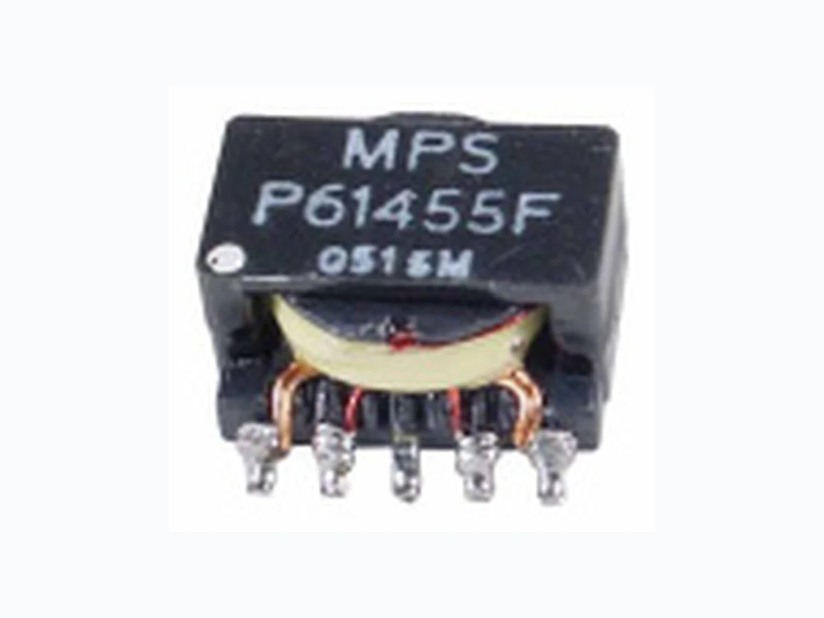
P61455F MPSIND
Document overview
- PDF pages: 1
Technical content
Page 1

FLYBACK TRANSFORMER
- RoHS compliant
- For DC-DC switch-mode flyback topology
- Switching frequency to 600KHz
- 10 Watts power hndling capability
- ER11/5 platform
- Minimum interwinding breakdown voltage of 1500Vrms
| ELECTRICAL SPECIFICATION @ 25°C | ||||||||
| Part Number | OCL | Leakage Inductance | DCR | Ratio | Hi-Pot | |||
| (µH ±5%) | (µH typ.) | (W typ.) | (±2%) | (mA max.) | ||||
| @100KHz 0.1Vrms | @100KHz 0.1Vrms | 1-5 | 7-10 | 6-9 | 2-4 | @10KHz 1Vrms | @ 1500Vrms 2 sec. | |
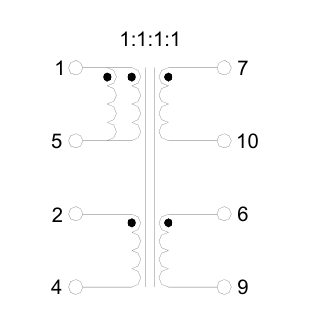
| P61455F | 4.0 | 0.13 | .013 | .030 | .026 | .044 | 1:1:1:1 | 0.5 |
- Other turns ratios can be developed on request. Please contact MPS Engineering Team for further information.
Mechanical
Schematic
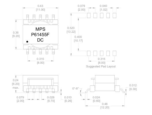
Dimensions
Unless otherwise specified, all tolerances are: .XX ± 0.010” & .XXX ± 0.003” Inches [mm]
P61455F-B
Product performance is limited to specified parameter. Data is subject to change without prior notice.
0515TA
Phone: (310)533-1455
2463 208th, Ste. 205
http://www.mpsind.com
Fax: (310)533-1853
Torrance, CA 90501
Email: sales@mpsind.com