

 Download PDF
P613P MPSIND
Document overview
- PDF pages: 1
Technical content
Page 1

FLYBACK TRANSFORMERS
P613P SERIES
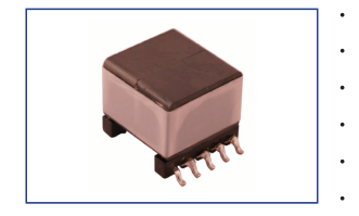
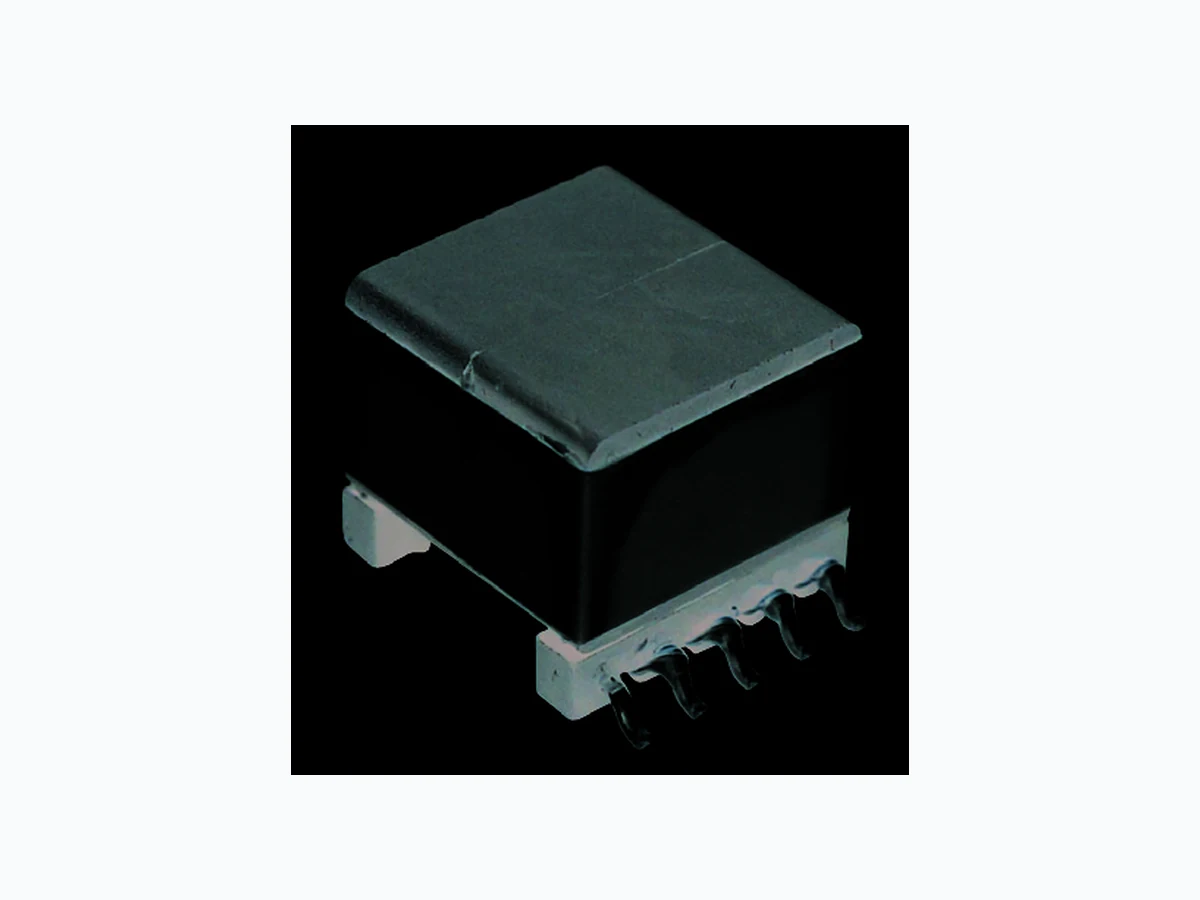
Flyback transformers for 13 Watt and 25 Watt PoE applications
Operating Frequency 250KHz
Isolation 1500Vrms, 60 seconds (Pri, Aux to Sec)
Operating Temperature -40ºC to +125ºC
RoHS Compliant Product
Custom Design Available
| ELECTRICAL PARAMETERS @ 25°C | ||||||||||
|---|---|---|---|---|---|---|---|---|---|---|
| Part Number P613P- | Power (W) | Pri OCL (μH) ±10% | DCR (mΩ MAX) | Pri L L (μH MAX) | Turns Ratio ±5% | Output Sec V / A | Schematic | |||
| Pri | Sec | Aux | Pri:Sec | Pri:Aux | ||||||
| 33A | 13 | 127 | 0.255 | 0.024 | 0.31 | 1.25 | 1 : 0.116 | 1 : 0.50 | 3.3 / 4 | A |
| 50A | 13 | 127 | 0.222 | 0.039 | 0.348 | 0.95 | 1 : 0.250 | 1 : 0.50 | 5.0 / 2.6 | A |
| 12A | 13 | 127 | 0.200 | 0.065 | 0.308 | 0.65 | 1 : 0.500 | 1 : 0.50 | 12 / 1.08 | A |
| 19A | 13 | 127 | 0.290 | 0.066 | 0.355 | 0.80 | 1 : 0.567 | 1 : 0.50 | 19.5 / 0.67 | A |
| 24A | 13 | 127 | 0.255 | 0.067 | 0.315 | 0.60 | 1 : 0.667 | 1 : 0.50 | 24 / 0.54 | A |
| 33B | 25 | 37 | 0.089 | 0.0046 | 0.096 | 0.75 | 1 : 0.150 | 1 : 0.60 | 3.3 / 7.5 | B |
| 50B | 25 | 37 | 0.089 | 0.0062 | 0.074 | 0.75 | 1 : 0.200 | 1 : 0.50 | 5 / 5 | B |
Note: 1. Primary OCL measured @ 250KHz 0.7Vrms 2. Primary Leakage L measured @ 250KHz 0.7Vrms with all Sec shorted 3. DCR measured with windings in parallel 4. Hi-pot: 1500Vrms, 1mA, 60s (Pri, Aux to Sec); 1800Vrms, 1mA, 5s (Pri, Aux, Core to Sec); 500Vrms, 1mA, 5s (between Pri, Aux, and Core)
Product performance is limited to specified parameters. Data is subject to change without prior notice.
Tel: 310-325-1043 Fax: 310-325-1044
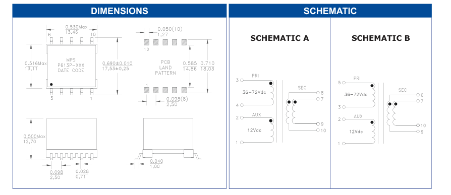
Dimensions Unless otherwise specified, all tolerances are: inch: .XX : ±0.010 .XXX : ±0.005 mm: X,X : ±0,254 X,XX : ±0,13
www.mpsind.com sales@mpsind.com