
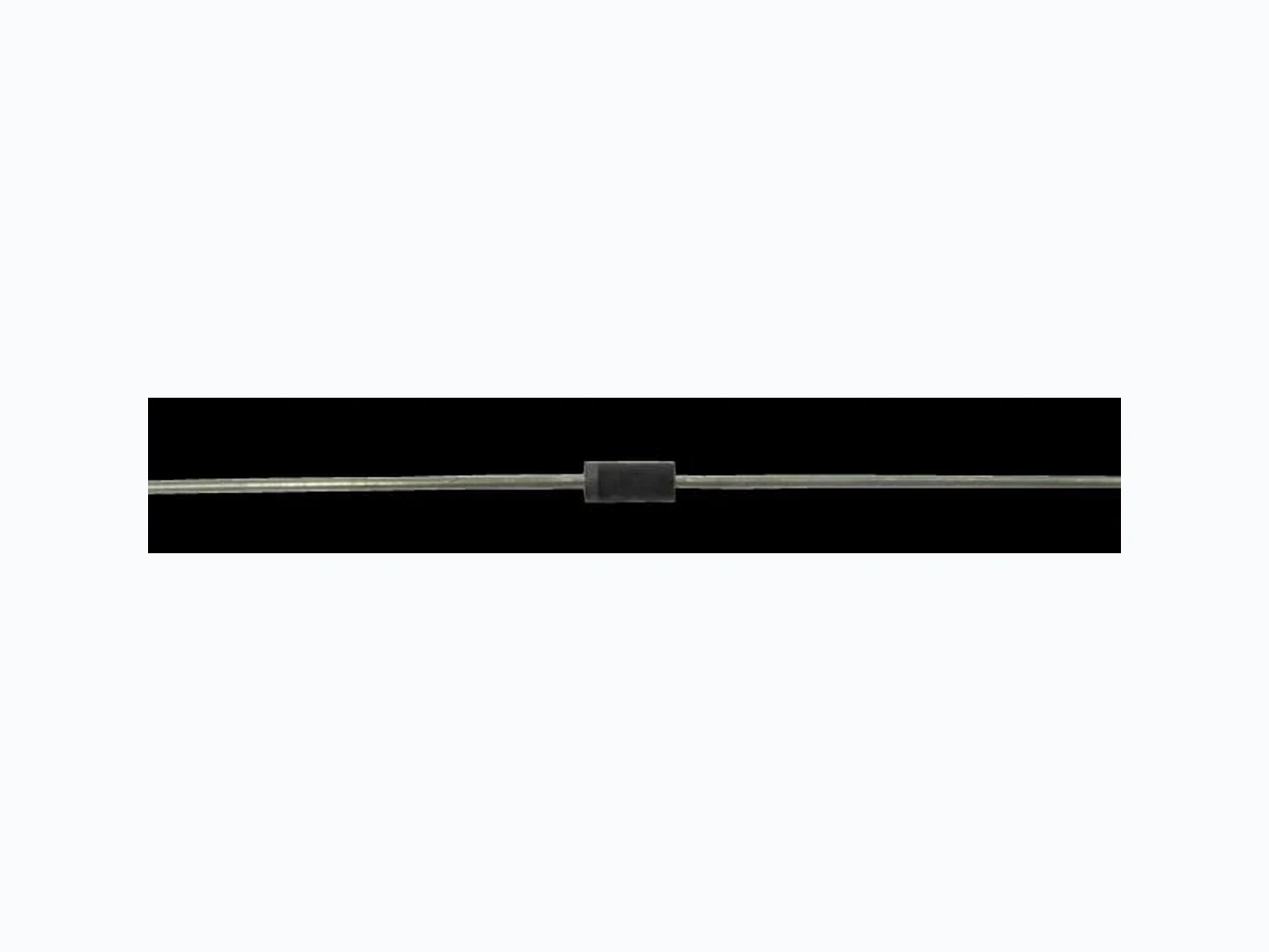
P5KE5.0 ETC2
Document overview
- Manufacturer or author: Provided By www.digicamel.com(FREE DATASHEET DOWNLOAD SITE)
- PDF pages: 4
Technical content
Features
Breakdown Voltages (VBR) from 5.0 to 170V 500W peak pulse power capability with a 10/1000μs waveform, repetitive rate (duty cycle):0.01% Fast Response Time Low incremental surge resistance Excellent clamping capability Available in uni-directional and bi-directional High temperature soldering guaranteed: 265℃ /10 seconds, 0.375” (9.5mm) lead length, 5lbs. (2.3kg) tension Application Use in sensitive electronics protection against voltage transients induced by inductive load switching and lighting on ICS, MOSFE, signal lines of sensor units for consumer, computer, industrial, automotive and telecommunication Mechanical Data Case: Void-free transfer molded thermosetting epoxy body meeting UL94V-O Terminals: Tin-Lead or ROHS Compliant annealed matte-Tin plating readily solderable per MIL-STD-750, Method 2026 Marking: Body marked with part number Polarity: Band denotes cathode. Bidirectional not marked Weight: 0.3g(Approximately) CASE: DO-204AL (DO-41) Dimensions in inches and (millimeters) 打印无效
P5KE5.0 thru P5KE170CA Document Number: P5KE5.0 thru P5KE170CA www.smsemi.com Feb.29,2012 2 Part Number Breakdown Voltage VBR @ IBR Rated Stand Off Voltage Maximum Standby current ID @ VWM Maximum Peak Pulse Current Maximum Clamping Voltage VC @ IPP Maximum Temperature Coefficient of V(BR) MIN MAX VBR(V) IBR(mA) VWM(V) ID(µA) IPP (A) VC(V) α v(BR) (%/℃) P5KE5.0 P5KE5.0A P5KE6.0 P5KE6.0A 6.40 6.40 6.67 6.67 7.30 7.00 8.15 7.37 5.0 5.0 6.0 6.0 600 600 600 600 52.0 54.3 43.9 48.5 9.6 9.2 11.4 10.3 .057 .057 .059 .059 P5KE6.5 P5KE6.5A P5KE7.0 P5KE7.0A 7.22 7.22 7.78 7.78 8.82 7.98 9.51 8.60 6.5 6.5 7.0 7.0 400 400 150 150 40.7 44.7 37.8 41.7 12.3 11.2 13.3 12.0 .061 .061 .065 .065 P5KE7.5 P5KE7.5A P5KE8.0 P5KE8.0A 8.33 8.33 8.89 8.89 10.20 9.21 10.90 9.83 7.5 7.5 8.0 8.0 35.0 38.8 33.3 36.7 14.3 12.9 15.0 13.6 .067 .067 .070 .070 P5KE8.5 P5KE8.5A P5KE9.0 P5KE9.0A 9.44 9.44 10.00 10.00 11.50 10.40 12.20 11.10 8.5 8.5 9.0 9.0 31.4 34.7 29.5 32.5 15.9 14.4 16.9 15.4 .073 .073 .076 .076 P5KE10 P5KE10A P5KE11 P5KE11A 11.10 11.10 12.20 12.20 13.60 12.30 14.90 13.50 10.0 10.0 11.0 11.0 26.6 29.4 24.9 27.4 18.8 17.0 20.1 18.2 .078 .078 .081 .081 P5KE12 P5KE12A P5KE13 P5KE13A 13.30 13.30 14.40 14.40 16.30 14.70 17.60 15.90 12.0 12.0 13.0 13.0 22.7 25.1 21.0 23.2 22.0 19.9 23.8 21.5 .082 .082 .084 .084 P5KE14 P5KE14A P5KE15 P5KE15A 15.60 15.60 16.70 16.70 19.10 17.20 20.40 18.50 14.0 14.0 15.0 15.0 19.4 21.5 18.8 20.6 25.8 23.2 26.9 24.4 .086 .086 .087 .087 P5KE16 P5KE16A P5KE17 P5KE17A 17.80 17.80 18.90 18.90 21.80 19.70 23.10 20.90 16.0 16.0 17.0 17.0 17.6 19.2 16.4 18.1 28.8 26.0 30.5 27.6 .088 .088 .090 .090 P5KE18 P5KE18A P5KE20 P5KE20A 20.00 20.00 22.20 22.20 24.40 22.10 27.10 24.50 18.0 18.0 20.0 20.0 15.5 17.2 13.9 15.4 32.2 29.2 35.8 32.4 .092 .092 .093 .093 P5KE22 P5KE22A P5KE24 P5KE24A 24.40 24.40 26.70 26.70 29.80 26.90 32.60 29.50 22.0 22.0 24.0 24.0 12.7 14.1 11.6 12.8 39.4 35.5 43.0 38.9 .094 .094 .096 .096 P5KE26 P5KE26A P5KE28 P5KE28A 28.90 28.90 31.10 31.10 35.30 31.90 38.00 34.40 26.0 26.0 28.0 28.0 10.7 11.9 9.9 11.0 46.6 42.1 50.0 45.4 .097 .097 .098 .098 P5KE30 P5KE30A P5KE33 P5KE33A 33.30 33.30 36.70 36.70 40.70 36.80 44.90 40.60 30.0 30.0 33.0 33.0 9.3 10.3 8.5 9.4 53.5 48.4 59.0 53.3 .099 .099 .100 .100 P5KE36 P5KE36A P5KE40 P5KE40A 40.0 40.0 44.4 44.40 48.9 44.2 54.3 49.1 36.0 36.0 40.0 40.0 7.8 8.6 7.0 7.8 64.3 58.1 71.4 64.5 .101 .101 .101 .101 打印无效
P5KE5.0 thru P5KE170CA Document Number: P5KE5.0 thru P5KE170CA www.smsemi.com Feb.29,2012 3 Part Number Breakdown Voltage VBR @ IBR Rated Stand Off Voltage Maximum Standby current ID @ VWM Maximum Peak Pulse Current Maximum Clamping Voltage VC @ IPP Maximum Temperature Coefficient of VBR MIN MAX VBR(V) IBR(mA) VWM(V) ID(µA) IPP (A) VC(V) %/℃ P5KE43 P5KE43A P5KE45 P5KE45A 47.8 47.8 50.0 50.0 58.4 52.8 61.1 55.3 43.0 43.0 45.0 45.0 6.5 7.2 6.2 6.9 76.7 69.4 80.3 72.7 .102 .102 .102 .102 P5KE48 P5KE48A P5KE51 P5KE51A 53.3 53.3 56.7 56.7 65.1 58.9 69.3 62.7 48.0 48.0 51.0 51.0 5.8 6.5 5.5 6.1 85.5 77.4 91.1 82.4 .103 .103 .103 .103 P5KE54 P5KE54A P5KE58 P5KE58A 60.0 60.0 64.4 64.4 73.3 66.3 78.7 71.2 54.0 54.0 58.0 58.0 5.2 5.7 4.9 5.3 96.3 87.1 103.0 93.6 .104 .104 .104 .104 P5KE60 P5KE60A P5KE64 P5KE64A 66.7 66.7 71.1 71.1 81.5 73.7 86.9 78.6 60.0 60.0 64.0 64.0 4.7 5.2 4.4 4.9 107.0 96.8 114.0 103.0 .104 .104 .105 .105 P5KE70 P5KE70A P5KE75 P5KE75A 77.8 77.8 83.3 83.3 95.1 86.0 102.0 92.1 70.0 70.0 75.0 75.0 4.0 4.4 3.7 4.1 125.0 113.0 134.0 121.0 .105 .105 .105 .105 P5KE78 P5KE78A P5KE85 P5KE85A 86.7 86.7 94.4 94.4 106.0 95.8 115.0 104.0 78.0 78.0 85.0 85.0 3.6 4.0 3.3 3.6 139.0 126.0 151.0 137.0 .106 .106 .106 .106 P5KE90 P5KE90A P5KE100 P5KE100A 100.0 100.0 111.0 111.0 122.0 111.0 136.0 123.0 90.0 90.0 100.0 100.0 3.1 3.4 2.8 3.1 160.0 146.0 179.0 162.0 .107 .107 .107 .107 P5KE110 P5KE110A P5KE120 P5KE120A 122.0 122.0 133.0 133.0 149.0 135.0 163.0 147.0 110.0 110.0 120.0 120.0 2.6 2.8 2.3 2.0 196.0 177.0 214.0 193.0 .107 .107 .107 .107 P5KE130 P5KE130A P5KE150 P5KE150A 144.0 144.0 167.0 167.0 176.0 159.0 204.0 185.0 130.0 130.0 150.0 150.0 2.2 2.4 1.9 2.1 231.0 209.0 268.0 243.0 .108 .108 .108 .108 P5KE160 P5KE160A P5KE170 P5KE170A 178.0 178.0 189.0 189.0 218.0 197.0 231.0 209.0 160.0 160.0 170.0 170.0 1.7 1.9 1.6 1.8 287.0 259.0 304.0 275.0 .108 .108 .108 .108 1. For bi-directional construction, indicate a C or CA suffix after part number, i.e. P5KE170C or P5KE170CA 打印无效
P5KE5.0 thru P5KE170CA Document Number: P5KE5.0 thru P5KE170CA www.smsemi.com Feb.29,2012 4 Characteristic Curve Fig.3 Derating Curve Fig. 1 Peak Pulse Power vs. Pulse Time Fig.2 Pulse Waveform for Exponential Surge PPP - Peak Pulse Power (kW) 100 1.0 0.1 0.1 1.0 10 102 103 104 tw-Pulse Width (µs) Fig.4 Typical Capacitance vs. Breakdown Voltage (Unipolar) 0 1.0 2.0 3.0 t-Time (ms) tr=10µs Peak Value IPP Half Value IPP 10/1000µs Waveform as defined by R.E.A. 150 100 IPP - Peak Pulse Current - % IPP 1 10 102 103 VBR – Breakdown Voltage (V) 100 PPP-Peak Pulse Power or continuous Average Power in Percent of 25 ℃ (%) Peak Pulse Power (Single pulse). Average Power Measured at Zero Bias Measured at Stand-off Voltage 104 103 102 C J– Junction Capacitance (pF) Impulse Exponential Decay 1.0 0.5 IPP IPP tW tW tW=0.71p tp Half Sine Square Wave Current Waveforms tW 0 50 100 150 200 Lead or Ambient Temperature (℃) Fig.5 Max. Non-Repetitive Forward Surge Current Uni-Directional Only 1 10 100 Number of Cycles at 60HZ 100 Peak Forward Surge Current (A) TJ=TJ Max. 8.3ms Single Half Sine-Wave 打印无效