
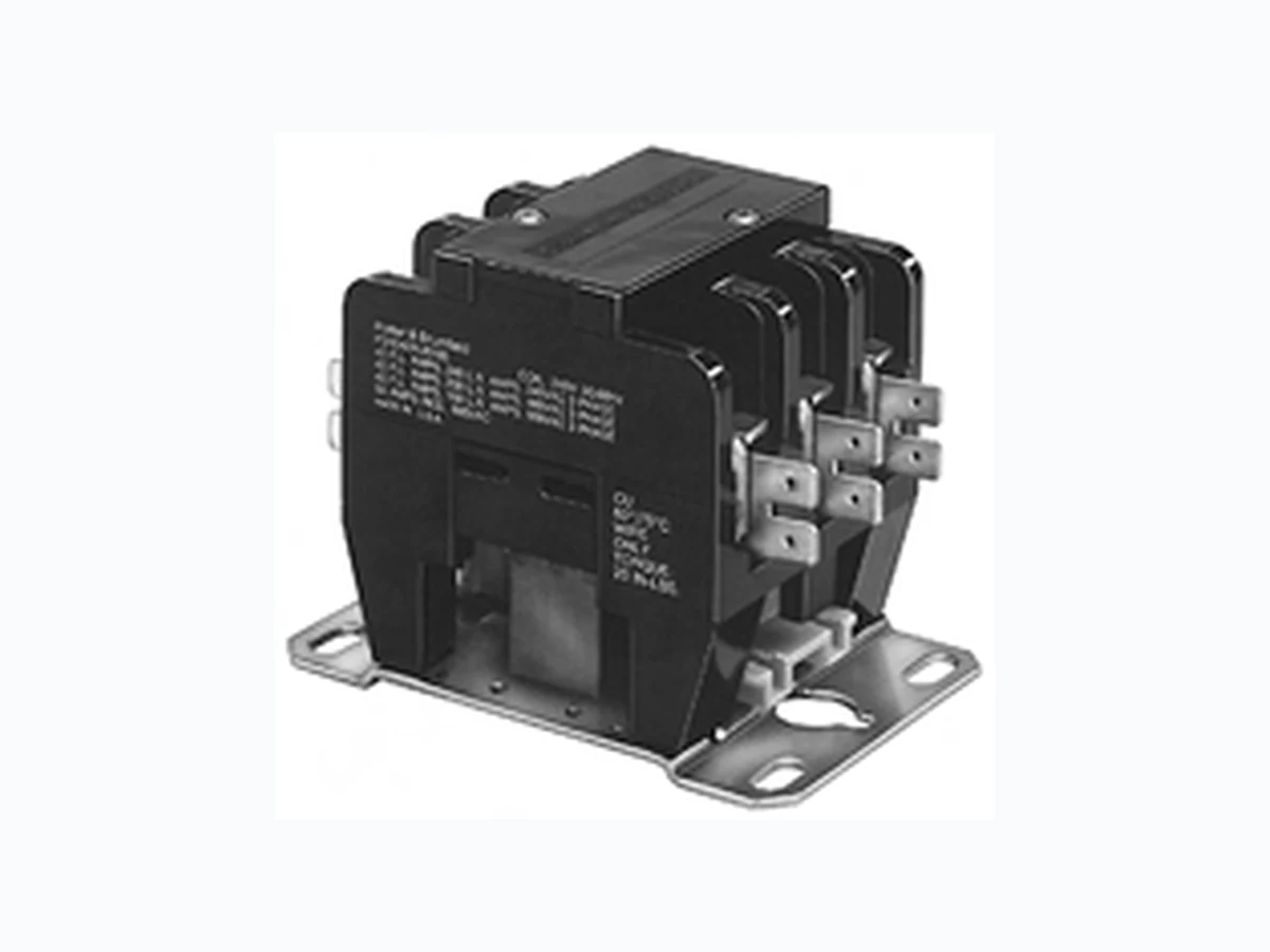
P31 MACOM
Document overview
- Manufacturer or author: Provided By www.digicamel.com(FREE DATASHEET DOWNLOAD SITE)
- PDF pages: 2
Technical content
Features
- 3 phase and single phase switching.
- Integral dual QC terminals.
- Class “B” coil insulation.
- Variety of main terminals.
- Applications include HVAC industrial control.
- Direct activated DC coils. Contact Data @ 25°C Main Contacts: Arrangements: 3 Form X (3PST -NO-DM) and 4 Form X (4PST -NO-DM). Ratings: See Main Contact Ratings Table. Material: Silver-cadmium oxide. Initial Breakdown Voltage:2,200V rms minimum between all elements and between all elements to ground. Expected Life: 200,000 operations at motor load. 500,000 operations, mechanical. Minimum Contact Data: 3A @ 120VAC. Initial Dielectric Strength Initial Breakdown Voltage:2,200V rms minimum between all elements and between all elements and ground. Main Contact Ratings @ 25°C, 60 Hz. AC (Per Pole) Coil Data @ 25°C Voltage: 12 and 24V DC. See Coil Data table. Power: 8W. Duty Cycle: Continuous. Insulation: Class B. Initial Insulation Resistance: 100 megohms minimum. Coil Data @ +25°C *Applicable for vertical or horizontal mounting, but not for upside-down mounting. Note: Coil suppression is recommended for all units. Operate Data @ 25°C Must-Operate Voltage:See Coil Data Table. Environmental Data T emperature Range:–55°C to +65°C. Mechanical Data Mounting: Universal mounting bracket. See Outline Drawings. T ermination: Contacts: Dual .250” (6.35mm) quick connect with or without binder head screw or box lug. Coil: Dual .250” (6.35mm) quick connect. Weight: 18 oz. (510g) approximately. P31/P41 series Definite Purpose Magnetic Contactor 16 to 40 Amp Full Load 20 to 50 Amp Resistive File E25575 File LR15734 P31C 150 25 125 25 100 25 35 P31E 240 40 200 40 160 40 50 P41B 120 20 100 20 80 20 25 P41C 150 25 125 25 100 25 35 @ 240VAC @ 480VAC @ 600VAC LRA FLA LRA FLA LRA FLA RES Our authorized distributors are more likely to maintain the following items in stock for immediate delivery. None at present. P31 P41 DFO 12DC 21 9 571 DHO 24DC 84 18 286 DC Nominal Nominal Resistance Must CoilCode Voltage in Ohms Operate Current ±1 0 % Voltage (mA)
Ordering Information
T ypical Part No.B P41 C 47 D HO 1 03 1. T ype: P31 = 3 Pole P41 = 4 Pole 2. Contact Rating C = 25 Amp E = 40 Amp (40A rating only offered on P31) 3. Contact Arrangement: 42 = 3 Form X (3PST -NO-DM) 47 = 4 Form X (4PST -NO-DM) P41 only 4. Coil Input: D = Direct Current (Direct Operated) 5. Coil Voltage: FO = 12VDC, with coil cover HO = 24VDC, with coil cover 6. Coil T erminal Location And Marking (See T erminal Location and Marking Diagram): 1 = Dual .250” (6.35mm) quick connect 7 . Contact T erminals (See Contact T erminal Options Diagram): 03 = Dual .250” (6.35mm) quick connect turned up per Figure 03 (25 amps, Max.) 05 = #10-32 binder head screw with dual .250” (6.35mm) quick connect per Figure 05 08 = Aluminum box lug (for #4-#14 copper wire) with dual .250” (6.35mm) quick connect per Figure 08 Users should thoroughly review the technical data before selecting a product part number. It is recommended that users also seek out the pertinent approvals files of the agencies/laboratories and review them to ensure the product meets the requirements for a given application.
P&B Dimensions are shown for reference purposes only. Dimensions are in inches over (millimeters) unless otherwise specified. Catalog 1308242 Issued 3-03 (PDF Rev. 1-06) Specifications and availability subject to change. www.tycoelectronics.com Technical support: Refer to inside back cover. 2.725 MAX. (69.22) 2.870 MAX. (72.90) 1.500 ± .010 (38.10 ± .25) 2.000 ± .010 (50.80 ± .25) 2.550 MAX. (64.77) .210 ± .010 (5.33 ± .25) .250 ± .005 (6.35 ± .13) 1.000 ± .010 (25.40 ± .25) 2.415 MAX. (2.67 ± .13)
10 PLACES
3.800 MAX. (96.52) 3.250 ± .010 (82.55 ± .25) 3.125 ± .010 (79.38 ± .25) .062 ± .005 (1.57 ± .13) COIL TERMINALS T1 T2 T3 L1 L2 L3 P31 P41 2.725 MAX. (69.22) 2.730 MAX. (69.34).250 ± .005 (6.35 ± .13) 1.500 ± .010 (38.10 ± .25) 2.000 ± .010 (50.80 ± .25) 2.550 MAX. (64.77) .210 ± .010 (5.33 ± .25) 1.000 ± .010 (25.40 ± .25) 2.630 MAX. (66.80) .105 ± .005 R. (2.67 ± .13) 3.800 MAX. (96.52) 3.250 ± .010 (82.55 ± .25) 3.125 ± .010 (79.38 ± .25) .210 ± .010 (5.33 ± .25) COIL TERMINALS T1 T2 T3 T4 L1 L2 L3 L4 Top View Top View .210 ± .010 (5.33 ± .25) LOAD SIDE LINE SIDE LOAD SIDE LINE SIDE #10-32 UNF-2B Tapped Hole .250” (6.35mm) Quick Connect Turned Up #10-32 UNF-2A X .375” (9.525mm) Binder Head Screw Screw With #12 Binder Head Screw With Captive Pressure Plate Box Lug Connector Figure 02 Figure 03 Figure 05 Figure 06 Figure 07 Figure 08 Outline Dimensions Contact T erminal Options