

 Download PDF
P192 MPSIND
Document overview
- PDF pages: 1
Technical content
Page 1
POWER FACTOR

CORRECTION INDUCTORS
P192 SERIES
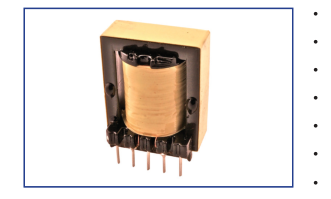
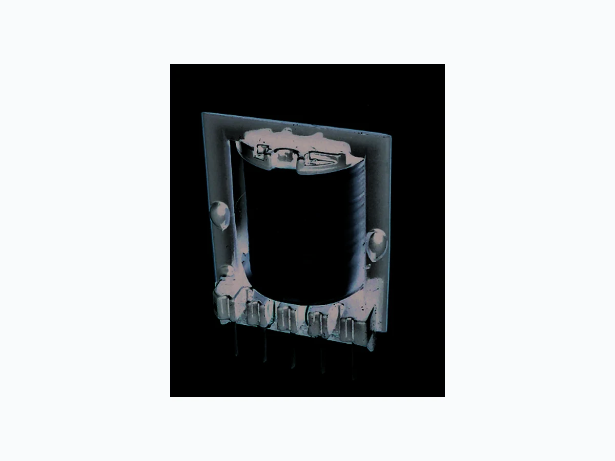
PCB mounted PFC inductor with Aux winding
Ultra low audio noise design
Ultra low heat dissipation design
Switching Frequency: >45KHz
Input: 85Vac - 265Vac, 43Hz - 63Hz
Operating Temperature: -40°C to +100°C
RoHS compliant product
| ELECTRICAL PARAMETERS @ 25°C | ||||||
|---|---|---|---|---|---|---|
| Part Numb P192- | er L (3-4) (Pri) (μH ±10%) | Idc (A) | Rdc (3-4) (Ω MAX) | Rdc (9-10) (Aux) (Ω MAX) | Turns Ratio Pri:Aux (±2%) | Dimension |
| 501-2 | 500 | 2.5 | 0.20 | 0.18 | 5 : 1 | A |
| 401-3 | 400 | 3.0 | 0.20 | 0.18 | 5 : 1 | A |
| 301-4 | 300 | 4.0 | 0.20 | 0.18 | 5 : 1 | A |
| 601-2 | 600 | 2.5 | 0.20 | 0.18 | 5 : 1 | B |
| 501-3 | 500 | 3.0 | 0.15 | 0.25 | 5 : 1 | B |
| 401-4 | 400 | 4.0 | 0.15 | 0.25 | 5 : 1 | B |
| 301-5 | 300 | 5.5 | 0.15 | 0.30 | 5 : 1 | B |
Note: 1. Inductance test @ 100KHz, 0.1Vrms 2. Idc: 10% roll off max from initial inductance value 3. Hipot: 1500Vrms, 5S, 1 mA, Pri to Aux
Product performance is limited to specified parameters. Data is subject to change without prior notice.
Tel: 310-325-1043 Fax: 310-325-1044
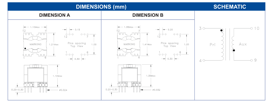
Dimensions Unless otherwise specified, all tolerances are: inch: .XX : ±0.015 .XXX : ±0.004 mm: X,X : ±0,38 X,XX : ±0,10
www.mpsind.com sales@mpsind.com