


 Download PDF
P191 MPSIND
Document overview
- PDF pages: 2
Technical content
Page 1
PASSIVE POWER FACTOR
CORRECTION INDUCTORS
P191 SERIES
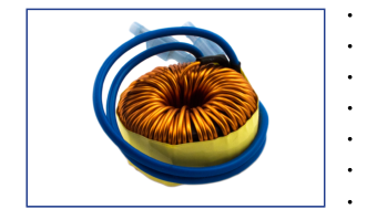

Design for power factor correction with high flux density material
20% to 50% smaller than traditional designs
Switching Frequency: 32KHz Min.
AC Line Voltage: 265Vac Max.
High Frequency 200 kHz – 700 kHz
Operating Temperature: -40°C to +130°C
Custom Design Available
| ELECTRICAL PARAMETERS @ 25°C | ||||||||
|---|---|---|---|---|---|---|---|---|
| Part Number P191- | L (μH ±15%) | R DC (Ω MAX) | I DC (A) | DIM A Max (mm) | DIM B Max (mm) | DIM C Nom (mm) | DIM D Nom (mm) | DIM E Nom (mm) |
| 301-1 | 300 | 0.50 | 1.0 | 21.0 | 11.0 | 9.0 | 18.0 | 0.40 |
| 501-1 | 500 | 0.65 | 1.0 | 21.0 | 11.0 | 9.0 | 18.0 | 0.40 |
| 751-1 | 750 | 0.90 | 1.0 | 23.0 | 12.5 | 10.0 | 20.0 | 0.40 |
| 102-1 | 1000 | 1.20 | 1.0 | 25.0 | 11.0 | 9.0 | 22.5 | 0.40 |
| 152-1 | 1500 | 1.20 | 1.0 | 27.5 | 12.5 | 10.5 | 25.0 | 0.40 |
| 202-1 | 2000 | 2.00 | 1.0 | 29.0 | 13.5 | 11.0 | 26.0 | 0.40 |
| 301-2 | 300 | 0.32 | 2.0 | 26.0 | 12.0 | 10.0 | 23.0 | 0.60 |
| 501-2 | 500 | 0.40 | 2.0 | 29.0 | 14.0 | 11.0 | 26.0 | 0.60 |
| 751-2 | 750 | 0.60 | 2.0 | 31.0 | 17.0 | 13.0 | 28.0 | 0.60 |
| 102-2 | 1000 | 0.80 | 2.0 | 32.0 | 18.0 | 14.0 | 29.0 | 0.60 |
| 152-2 | 1500 | 0.85 | 2.0 | 34.0 | 19.0 | 15.5 | 30.0 | 0.60 |
| 202-2 | 2000 | 0.95 | 2.0 | 34.0 | 19.0 | 15.5 | 30.0 | 0.60 |
| 301-3 | 300 | 0.20 | 3.0 | 30.0 | 15.0 | 11.5 | 26.5 | 0.80 |
| 501-3 | 500 | 0.30 | 3.0 | 31.0 | 16.5 | 12.5 | 27.5 | 0.80 |
| 751-3 | 750 | 0.32 | 3.0 | 34.0 | 18.0 | 15.5 | 31.0 | 0.80 |
| 102-3 | 1000 | 0.40 | 3.0 | 36.0 | 20.0 | 16.0 | 32.0 | 0.80 |
| 152-3 | 1500 | 0.43 | 3.0 | 43.0 | 21.0 | 16.0 | 39.0 | 0.80 |
| 301-5 | 300 | 0.10 | 5.0 | 35.0 | 20.0 | 16.0 | 31.5 | 1.00 |
| 501-5 | 500 | 0.15 | 5.0 | 42.0 | 17.0 | 15.0 | 37.5 | 1.00 |
| 751-5 | 750 | 0.18 | 5.0 | 47.0 | 21.0 | 18.0 | 43.5 | 1.00 |
| 102-5 | 1000 | 0.20 | 5.0 | 49.0 | 23.0 | 19.0 | 45.0 | 1.00 |
| 152-5 | 1500 | 0.26 | 5.0 | 55.0 | 25.0 | 20.0 | 51.5 | 1.00 |
| 301-7 | 300 | 0.06 | 7.0 | 45.0 | 23.0 | 18.0 | 39.0 | 1.30 |
| 501-7 | 500 | 0.10 | 7.0 | 51.0 | 26.0 | 20.0 | 46.0 | 1.30 |
| 751-7 | 750 | 0.13 | 7.0 | 57.0 | 27.0 | 21.0 | 52.5 | 1.30 |
| 102-7 | 1000 | 0.18 | 7.0 | 57.0 | 27.0 | 21.0 | 52.5 | 1.30 |
Product performance is limited to specified parameters. Data is subject to change without prior notice.
Tel: 310-325-1043
www.mpsind.com
Fax: 310-325-1044
sales@mpsind.com
Page 2
PASSIVE POWER FACTOR

CORRECTION INDUCTORS
P191 SERIES
| ELECTRICAL PARAMETERS @25°C | |||||||
|---|---|---|---|---|---|---|---|
| Part Number P191- | L (μH ± | R DC 15%) (Ω MAX) | I DC (A) | DIM DI A Max B M (mm) (m | M DIM ax C Nom m) (mm) | DIM D Nom (mm) | DIM E Nom (mm) |
| 301-10 | 30 | 0 0.05 | 10.0 | 53.0 27 | .0 21.0 | 47.0 | 1.73 |
| 501-10 | 50 | 0 0.06 | 10.0 | 63.0 31 | .0 24.0 | 55.0 | 1.73 |
| 751-10 | 75 | 0 0.08 | 10.0 | 73.0 32 | .0 26.0 | 68.0 | 1.73 |
| 102-10 | 10 | 00 0.09 | 10.0 | 77.0 36 | .0 28.0 | 70.0 | 1.73 |
NOTES:
- Inductance test @ 10KHz, 0.1VRMS
- IDC: 10% roll off Typ (20% Max.) from initial inductance value
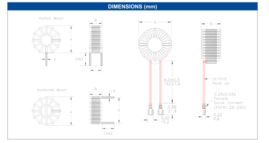
- Add -V for Vertical Mount, -H for Horizontal Mount, -W for Hook Up wire
- Extended length hook up wire with Fast-On available on request
Product performance is limited to specified parameters. Data is subject to change without prior notice.
Tel: 310-325-1043 Fax: 310-325-1044
Dimensions Unless otherwise specified, all tolerances are: inch: .XX : ±0.015 .XXX : ±0.004 mm: X,X : ±0,38 X,XX : ±0,10
www.mpsind.com sales@mpsind.com