
DATASHEET SEARCH SITE
Document overview
- Manufacturer or author: Provided By www.digicamel.com(FREE DATASHEET DOWNLOAD SITE)
- PDF pages: 27
Technical content
Datasheet sections
GPS/GLONASS/GALILEO/SBAS RECEIVERS NV08C-CSM v.3.x, v.4.x Datasheet Version 2.6 NVS Technologies AG Letzaustrasse 2, 9462 Montlingen Switzerland Tel +41 71 760 07 36 Fax +41 71 760 07 38 www.nvs-gnss.com
TITLE: NV08C-CSM DATASHEET V2.6 ENG, February 18, 2014 Page 2 of 27 CONFIDENTIAL. The information contained herein is the exclusiv e property of NVS Technologies AG and shall not be disclosed, distributed or reproduced in whole or in part without prior written permission of NVS Technologies AG.
Revision History
Revision ID Date Description
1.0 November 1, 2010 First version for distribution
1.1 December 27, 2010 General editing
2.3 January 17, 2012 General editing
2.4 March 12, 2012 General editing
2.5 January 22, 2014 General editing for HW release 4.1
2.6 February 18, 2014 Chapter Packaging information added
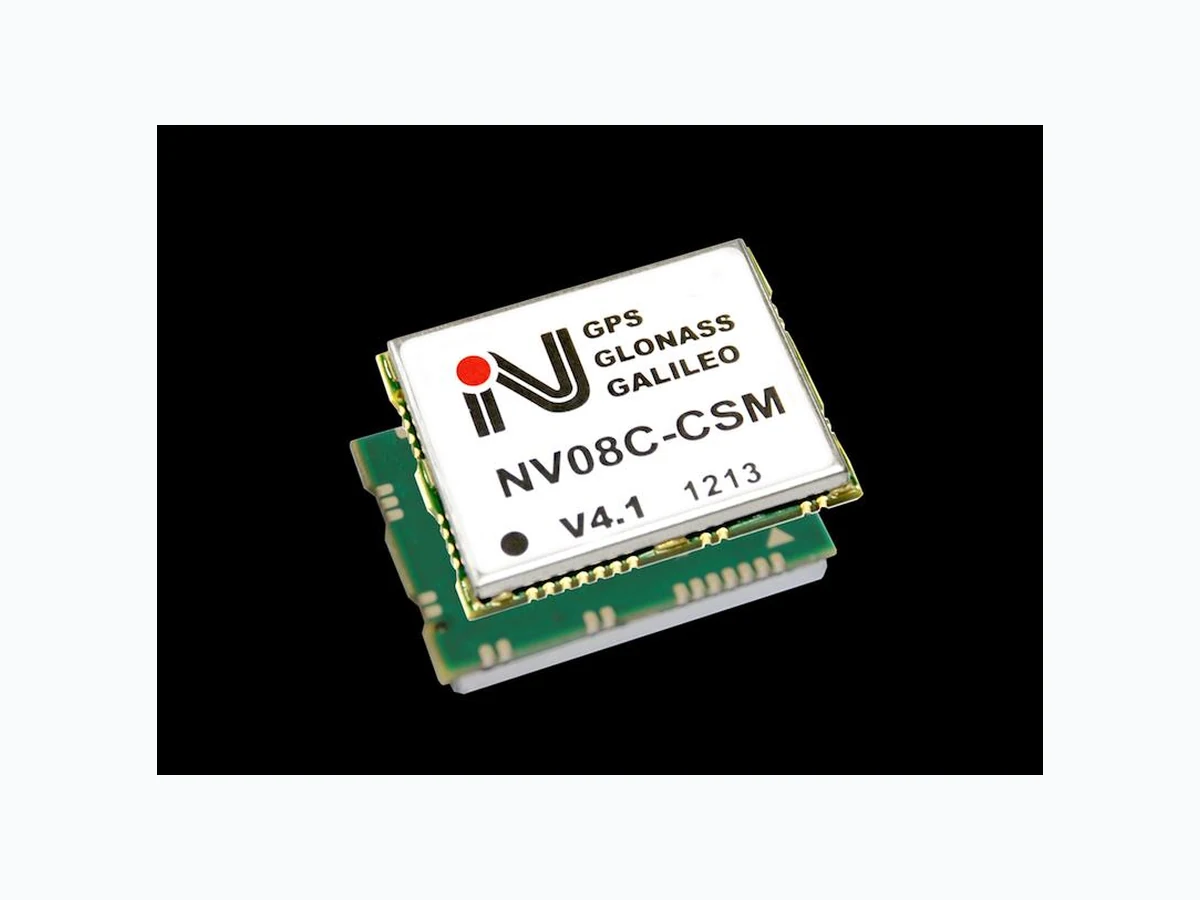
TITLE: NV08C-CSM DATASHEET V2.6 ENG, February 18, 2014 Page 4 of 27 CONFIDENTIAL. The information contained herein is the exclusiv e property of NVS Technologies AG and shall not be disclosed, distributed or reproduced in whole or in part without prior written permission of NVS Technologies AG. 1. Overview 1.1. Introduction The NV08C -CSM is a fully integ rated multi -constellation satellite navigation receiver. The NV08C -CSM’s key feature is its full compatibility with GPS, GLONASS and future global navigation satellite systems (GNSS) GALILEO, as well as Satellite Based Augmentation Systems (SBAS), EGNOS, W AAS and MSAS. The NV08C-CSM device is specifically designed for use in LBS and M2M applications, demanding low cost, low power consumption, small form factor and uncompromised performance. Applications: Fleet management/Telematics and anti-theft systems In-car and personal navigation devices Asset and personal tracking Surveillance and security systems LTE, WiMAX, Wi-Fi & cellular base station time synchronization The NV08C-CSM offers high sensitivity and high performance acquisition and tracking, low pow er consumption and assisted GPS/GLONASS/GALILEO (A -GNSS) functionality. Tracking satellites from multiple GNSS constellations ensures much higher availability of navigation signals when compared to single constellation alternatives, providing increased performance, accuracy and reliability to devices used in urban and industrial environments. It features two RF channels (GPS and GLONASS) and 3 -stage filtration for better noise immunity. As well, a variety of interfaces, flexible power supply options, and a supply voltage for an active antenna are provided. This very compact and fully featured GNSS receiver can be integrated on a low cost 2 or 4 layer PCB with minimum additional passive components. Evaluations Tools: An evaluation /development kit (NV08 C-EVK-CSM) is available to help developers quickly familiarise themselves with the NV08C -CSM’s features and functionalities. It is a flexible tool that allows users to evaluate the NV08C -CSM’s various modes of operation , as well as to override default configurations/settings and interfaces. The NV08C-EVK-CSM can be used with navigation systems to obtain current position (latitude, longitude and elevation), velocity and time , utilising all available Global N avigation Satellite Systems (GNSS), including GPS, GLONASS, GALILEO and SBAS signals, at any location on earth and at any time. Please visit http://nvs-gnss.com/products/evk/item/4-evk-csm.html for additional information.
TITLE: NV08C-CSM DATASHEET V2.6 ENG, February 18, 2014 Page 5 of 27 CONFIDENTIAL. The information contained herein is the exclusiv e property of NVS Technologies AG and shall not be disclosed, distributed or reproduced in whole or in part without prior written permission of NVS Technologies AG. Block diagram in Fig. 1. describes main internal blocks and interfaces of NV08C-CSM module. RF Supply LDO 1.2V BB core 1.8..3.3V User I/O 3.0..5.5V RF Supply Ext Reset 2.8V RF NV08C-CSM Vbat, 2.2..5.5V (optional) Baseband (NV08CD) SRAM ROM ARM7TDMI GPS/ GALILEO/ GLONASS Engine Backup RAMRTC Interfaces OTP RF Front-End TCXO RF GLONASS RF GPS/ GALILEO SPI SPI RTC XTAL UART A SPI/ GPIO3...7 TWI (I2C compatible) PPS & TimeMark Antenna Input 3.0..5.5V Digital Supply Power supervisor BB Supply DC/DC RESET GPS/GLONASS Diplexer SAW GLO SAW GPS SAW Filter SPI FLASH UART B LDO VANT, 2.65V GPIO0/ ANTFLAG RF I/O Supply LDO 2.8V RF I/O Fig. 1. NV08C-CSM Block Diagram 1.2. Navigation Features Parameter Description Supported GNSS signals L1 GPS/SBAS C/A L1 GLONASS СТ L1 GALILEO OS Data+Pilot Number of channels 32 channels each capable to receive any supported signal Time to first fix Cold star: 25 s (average) Warm start: 25 s (average) Hot start: 3 s (average) Sensitivity Cold star: – 143 dBm With A-GNSS: – 160 dBm Tracking mode: – 160 dBm Accuracy 1 Autonomous mode: <1.5 m Differential mode SBAS: <1 m Differential mode DGNSS: <1 m Height: <2 m Velocity: 0.05 m/s Assisted GNSS Supported 1PPS time accuracy 15 ns accuracy (rms), 38.5ns granularity (1/26 MHz) Update rate Up to 10Hz Limitations Velocity: less than 500 m/s Acceleration: less than 5 g Height: less than 50,000 m
1 RMS, 24hr static, SV @ –135 dBm
reproduced in whole or in part without prior written permission of NVS Technologies AG. automatically block the supply voltage to the RF input pin. protection will not operate. high channel separation and additional out-of-band interference attenuation. The parameters of the NV08C-CSM’s RF inputs are as shown in Table 1. Table 1. RF Input Parameters Note – Table 1 shows estimated values. The actual values may differ as a result of device qualification. to digital to be processed by the digital baseband IC. Typically both input channels are enabled to simultaneously receive all available navigation signals. However to save power, one of two channels may be disabled via software (“GPS Only” mode). a 26 MHz frequency generator (TCXO) with high temperature stability (±0.5 ppm).
TITLE: NV08C-CSM DATASHEET V2.6 ENG, February 18, 2014 Page 7 of 27 CONFIDENTIAL. The information contained herein is the exclusiv e property of NVS Technologies AG and shall not be disclosed, distributed or reproduced in whole or in part without prior written permission of NVS Technologies AG. Two UART (4,800 to 230,400 bit/s) 1PPS output/external synchronization pulse (input) 8 GPIO One SPI* One TWI (I2C compatible)* * requires a non-standard firmware load Supported protocols: IEC61162-1 (NMEA 0183) BINR (proprietary) RTCM v.2.x (messages #1, #31) Data update/output rate: 1, 2, 5, 10 Hz 1.6. Electrical Parameters The NV08C-CSM device requires the following power supply voltages: Digital I/O supply 1.8 to 3.3 V Digital and RF supply 3.0 to 5.5 V Backup memory and RTC clock 2.2 to 5.5 V The maximum power consumption is as follows: Continuous tracking mode: - GPS only 120 mW* - GNSS 180 mW* Sleep mode: - 100 µA* (All power supplies must be provided) Backup mode: - 4 µA @ 2.2 to 5.5 V (only RTC and Backup RAM supply) * average value. The Sleep Mode allows minimizing power consumption of NV08C device without turning off of all power supplies. NV08C devices are sleeping in thin mode (no signal tracking and navigation supported) . Refer to chapter 3.3. Sleep Mode for additional details. The Backup Mode is supported by an on-chip real-time clock and static RAM, in order to safe-keep true time and other parameters, while the main power is turned off. This feature allows the receiver’s start-up time (prior to receiving first valid navigation data) to be much shorter . To use the Backup Mode backup voltage must be provided to the VBAT pin (see chapters below).
reproduced in whole or in part without prior written permission of NVS Technologies AG. on customer’s PCB (plus test pads used exclusively in NV08C-CSM production). Fig. 2. Drawing and dimensions of the NV08C-CSM module (mm). Top view. Note – Test pads located on the bottom side of the module must remain unconnected on user’s PCB. CSM’s list of pins, along with their signal name, pin number, pin type and description. Table 2. Signal Type Definitions
reproduced in whole or in part without prior written permission of NVS Technologies AG. Table 3. List of Pins
1 GPIO2 I/O RESERVED, [TimeMark* (external sync pulse), GPIO*, TWI clock*]
2 GPIO1 I/O 1PPS output [TWI data*, GPIO*]
4 GPIO5 I/O Configuration pin [SPI A data MOSI* output (master)/ input (slave),
5 GPIO7 I/O Configuration pin [ SPI A Clock*, GPIO*]
6 GPIO3 I/O Configuration pin [ SPI A CS1*, GPIO*]
7 GPIO4 I/O Configuration pin [ SPI A data MISO* output (slave)/ input (master),
20 GPIO0 O
35 GPIO6 I/O Configuration pin [ GPIO*]
30 RX2 I Input UART B
31 TX2 O Output UART B
32 TX1 O Output UART A
33 RX1 I Input UART A
8 VIN_A PWR I Power supply for RF chain (LDO A)
21 SLEEP_FLAG O
Low power consumption mode flag.
23 VBAT PWR I BB battery supply
26 VIN_D PWR I Power supply for digital chain (LDO D)
28 VCCIO PWR I Power supply for IO’s
- These GPIO pin settings can be re-allocated by FW Patch (see 3.5. FW update).
reproduced in whole or in part without prior written permission of NVS Technologies AG. maximum ratings might cause permanent damage to the device. Table 4. Absolute Maximum Ratings Recommended operating conditions guarantee correct device operation. As long as the device is used within these ranges, electrical DC and AC characteristics are guaranteed. Table 5. Operating Ambient Temperature Table 6. Power Supply Voltage Table 7. Antenna Power Supply
1 Minimum current for the built-in active antenna detector
2 Maximum active antenna current
reproduced in whole or in part without prior written permission of NVS Technologies AG. Table 8. Input Voltage for GPIO7 – GPIO0 Table 9. Input Voltage for #RES (RESET) Table 10. Refer to Table 11 for resistor values (BB I/O cells). Table 10. I/O State after RESET
reproduced in whole or in part without prior written permission of NVS Technologies AG. Table 11. Pull-up and Pull-down Resistors Table 12. DC Characteristics Table 13. Current Consumptions
- Without active antenna current
- BRAM access rate less than 1M/s
- Load dependent, maximum current 4mA per digital IO
- RF portion switched off, module in power saving mode
TITLE: NV08C-CSM DATASHEET V2.6 ENG, February 18, 2014 Page 13 of 27 CONFIDENTIAL. The information contained herein is the exclusiv e property of NVS Technologies AG and shall not be disclosed, distributed or reproduced in whole or in part without prior written permission of NVS Technologies AG. 2.4. Hardware Integration Guide 2.4.1. Power Supply 2.4.1.1. Wiring NV08C-CSM to an External Power Supply Fig. 3 Provides the NV08C-CSM’s power connection diagram LDO D LDO AIN EN OUT IN EN OUT RF FE VRF I/O (2.8V) VRF (2.8V) BB Vbat (1.2V) Vcore (1.2V) VRF I/O (2.8V) VCCIO VBAT VIN_D VIN_A NV08C-CSM LDO_SHDN DC/DCIN OUT LDOIN OUT Fig. 3. NV08C-CSM Power Connection Diagram Four supply inputs for maximum system integration flexibility: Note – Supply voltages shown above are nominal values. Please refer to Table 6 for maximum upper and lower limits. The RF front-end is powered by the integrated LDO A and LDO D low-dropout linear regulators. The LDO A provides a clean analogue voltage supply to the RF section, and the LDO D provides a regulated voltage supply to the digital circuitry. The input power supply for the LDO A and LDO D (VIN_A and VIN_D) has a voltage range of 3.0 to 5.5V . The digital baseband (BB) uses three types of voltages: 1.2V as the core voltage (supplied by integrated DC/DC converter), IO voltage (VССIO, 1.8…3.3V) and a backup supply 1.2V for a Real -Time Clock and backup RAM (supplied by integrated LDO). The Backup power option (VBAT, 2.2…5.5V) must be powered for “hot start” and “warm start” functions. If not required VBAT must be connected to VIN_D. In User systems power may be provided to the NV08C-CSM in a number of different ways depending on specific design requirements and voltage suppl y availability . Some of the most common cases are described in the following sections.
reproduced in whole or in part without prior written permission of NVS Technologies AG. The external power supply V_IN must be connected to the VIN_A, VIN_D, VCCIO and VBAT pins as follows. Table 14. External Power Supply Voltage Range system’s IO voltage supply must be connected to VCCIO instead of V_IN. Table 15. External Power Supply Voltage Range
reproduced in whole or in part without prior written permission of NVS Technologies AG. power-on (warm and hot starts). provided by the User’s system. Table 16. Voltages of External Power Supply 1 For when VССIO connected to V_IN. 2 For when VССIO connected to V_IO. or by using inductive isolation. As an option power supply inputs may be equipped with capacitors as shown in the Table 17. Table 17. Power Supply Capacitors (optional)
reproduced in whole or in part without prior written permission of NVS Technologies AG. consumption via VCCIO is typically lower than the consumption of the RF, front end and baseband core. Table 18. Average Power Consumption of the NV08C-CSM in Time-to-Time-Fix Mode required the 1PPS output can be set to operate only when a valid position fix is available. $POUTC and BINR 72h message (generated within 20 ms after the 1PPS pulse). automatically blocked by short-circuit protection.
TITLE: NV08C-CSM DATASHEET V2.6 ENG, February 18, 2014 Page 17 of 27 CONFIDENTIAL. The information contained herein is the exclusiv e property of NVS Technologies AG and shall not be disclosed, distributed or reproduced in whole or in part without prior written permission of NVS Technologies AG. It is very important to choose a proper antenna. An active antenna with too much LNA gain and wide passband may reduce the quality of signal reception due to possible in-band and out -of-band interference. As well an active antenna with too little gain or with high cable attenuation may decrease the receiver’s sensitivity. Recommended active antenna parameters are as follows: GPS/GLONASS L1, bandwidth 35 MHz @ fc = 1590 MHz Gain including cable attenuation 20-30 dB Antenna noise figure <2 dB Out-of-band signal attenuation: at least 35dB @ fc ± 70 MHz. If the active antenna requires a supply voltage other than 2.65 V, an external antenna power supply can be applied as shown in Fig. 7. NV08C-CSM RF_IN RF_IN L1 0402 47nH VANT (3...12) V RF C1 0201 22pF LDO OUT IN EN SLEEP_FLAG VIN C2 0201 22pF NV08C-CSM RF_IN RF_IN L1 0402 47nH VANT (3...12) V RF C1 0201 22pF SLEEP_FLAG C2 0201 22pF Fig. 7. Connection Options for an external active antenna with an external power source Note – If an external power source is used , the built-in current detector and short circuit protection will not operate.
reproduced in whole or in part without prior written permission of NVS Technologies AG. two-wire interface (I2C compatible)* and GPIO interfaces. IO interfaces in NV08C-CSM are connected to external devices via 8 pins (GPIO7 – GPIO0). Table 19. Default Configuration of pins P7 – P0 synchronization input by FW Patch. Table 20. Configuration Settings
TITLE: NV08C-CSM DATASHEET V2.6 ENG, February 18, 2014 Page 19 of 27 CONFIDENTIAL. The information contained herein is the exclusiv e property of NVS Technologies AG and shall not be disclosed, distributed or reproduced in whole or in part without prior written permission of NVS Technologies AG. GPIO (I/O number) Function PIO value Description GPIO5 = 0 GPIO4 = 1 GPIO3 = 1 UART A – 19200 NMEA (GGA/1, RMC/1, GSV/1, GSA/1, RZD/1, GBS/10*) UART B – 57600 BINR GPIO5 = 1 GPIO4 = 0 GPIO3 = 0 UART A – 38400 NMEA (GGA/1, RMC/1, GSV/1, GSA/1, RZD/1, GBS/10*) UART B – 38400 BINR GPIO5 = 1 GPIO4 = 0 GPIO3 = 1 UART A – 38400 NMEA (GNS/1, RMC/1, GSA/1, GBS/10, GSV/10, DTM/30*) UART B – 4800 RТСМ GPIO5 = 1 GPIO4 = 1 GPIO3 = 0 UART A – 4800 NMEA (GNS/1, RMC/1, GSA/1, GBS/10, GSV/10, DTM/30*) UART B – 4800 RТСМ GPIO5 = 1 GPIO4 = 1 GPIO3 = 1 UART A – 57600 NMEA (GGA/1, RMC/1, GSV/1, GSA/1, RZD/1, GBS/10*) UART B – 57600 BINR * - default NMEA messages and time interval Note – By default the NMEA output is enabled (GNS/1s, RMC/1s, GSA/1s, GBS/10s, GSV/10s, DTM/30s messages) and the BINR output is disabled . To enable the BINR output a query message must be sent (see Protocol Specification). 2.4.6. Backup Power Supply VBAT If an independent VBAT voltage is applied , the NV08C-CSM module can store (in its BRAM) navigation parameters (almanac, ephemeris, last calculated coordinates etc.), as well as user defined settings (ports and receiver configuration settings). When navigation parameters are stored , the module is able to provide warm or hot start s (depending on its switch-off time and available navigation data). The user defined settings mode is defined by the GPIO7’s signal level (“1” – saved, “0” – not saved). By default the GPIO7 is pulled-up (“1”). If no VBAT voltage is applied to the module , all data saved in the BRAM will be erased when the module is powered off.
TITLE: NV08C-CSM DATASHEET V2.6 ENG, February 18, 2014 Page 20 of 27 CONFIDENTIAL. The information contained herein is the exclusiv e property of NVS Technologies AG and shall not be disclosed, distributed or reproduced in whole or in part without prior written permission of NVS Technologies AG. 3. Software and Protocols Reference 3.1. Data Protocol and Configuration The NV08C-CSM can interface to an external host-processor using the following protocols: BINR (proprietary binary protocol) NMEA 0183 RTCM v2.x (messages #1, #31) Note – See description of communication messages in the Protocol Specification document. By default, the module’s interfaces are configured as follows: UART A: Protocol NMEA, 115,200 bps UART B: Protocol BINR, 115,200 bps Note – Both ports can be configured to receive differential correctional data in RTCM format . Even in this configuration, it is still possible to control the module by adding NMEA -commands to the RTCM stream, since the NV08C-CSM’s SW is able to sort out data types. In order to use this option the port must first be activated by a $PORZA message to accept the RTCM data, then the NMEA message output stream can be defined by a $PORZB message. (Refer to the Protocol Specification document for $PORZA and $PORZB messages description.) Other NV08C-CSM default settings: navigation mode: GPS and GLONASS SBAS data: accounted automatically RAIM: automatic Assisted data: accounted automatically navigation data update rate: 1 Hz NMEA messages: GSA, RMC, GGA, GSV, GBS Standard settings can be changed by using the following means: pre-set configuration codes to assign certain specific GPIO inputs (refer to Table 20 GPIO7 – GPIO3 settings) NMEA/BINR protocol commands via UART А/В ports 3.2. Low Power Battery Mode The NV08C-CSM has a sophisticated system to reduce its power consumption. The supported power conservation methods are as follows: automatic clock gating of unused subsystems (such as the fast search function, unused correlation channels, and interface blocks) option to completely turn-off the power to one of the two analogue channels 3.3. Sleep Mode If navigation function is not required power consumption can be minimized by switching the NV08C - CSM device to Sleep mode. A Host system can activate the Sleep mode by sending the
TITLE: NV08C-CSM DATASHEET V2.6 ENG, February 18, 2014 Page 21 of 27 CONFIDENTIAL. The information contained herein is the exclusiv e property of NVS Technologies AG and shall not be disclosed, distributed or reproduced in whole or in part without prior written permission of NVS Technologies AG. $POPWR,1111*66<CR><LF> NMEA command. When NV08C -CSM enters the Sleep Mode SLEEP_FLAG pin goes to LOW state, Both RF-chains and TCXO are turned off and BB ASIC consumes minimal power. Note: The time int erval required for NV08C-CSM device to enter Sleep mode depends on the communication baud rate since NMEA commands should be received and decoded. After commands decoding a minimum of 10 ms is required for the device to safely enter Sleep mode. The NV08C-CSM device wakes up when the Host System sends any command via UART port. Note: The NV08C -CSM device is sensitive to the falling edge of UART RX signals. A minimum of 10 ms after detecting a falling edge is required to switch the device from IDLE to normal operation mode, otherwise the first sent command cannot be properly decoded. Therefore a timeout is required prior to sending of the next control command by the Host System. 3.4. Assisted GNSS The NV08C-CSM supports the use of external assisted data functions for applications that require quick- navigation on power-up. Assisted data is provided by the User’s system via wireless means such as GSM or CDMA, or by the Internet, and loaded onto the module via the BINR protocol. Assisted data comes in a compact format (binary data file) and is ready for download on supported sites. 3.5. FW update To download Patch Code (FW) via a UART interface (Fig. 8) the following command must be sent to the NV08C-CSM: - for NMEA protocol: $POPRL,R*2F\\r\\n - for BINR protocol: 0х10 0х01 0х52 0х45 0х4С 0x4F 0x41 0x44 0x5F 0x52 0x10 0x03 By receiving th e command the NV08C-CSM shifts into programming mode and starts the output of character 0x43 (in ASCII – character "C") to UART TX. In response the User's system must download Patch Code in the form of sequence of bytes ( provided as a binary file) by means of X-modem-CRC protocol. As soon as the binary file is completely downloaded the module stores the Patch Code in its non-volatile memory and restarts. NVS Technologies can support application specific requirements. Contact NVS’ Technical S upport for customisation of standard functionalities. The PatchWriter (Firmware downloading tool) and the latest revision of the Firmware Patch (FW) are available at www.nvs-gnss.com. NV08C-CSM TX RX External Device RX TX UART A / UART B Fig. 8. Connecting the NV08C-CSM to an external device to download Patch Code (FW)
TITLE: NV08C-CSM DATASHEET V2.6 ENG, February 18, 2014 Page 22 of 27 CONFIDENTIAL. The information contained herein is the exclusiv e property of NVS Technologies AG and shall not be disclosed, distributed or reproduced in whole or in part without prior written permission of NVS Technologies AG. FW updating via Patch downloads can be performed for an unlimited number of times (within the FLASH memory specification – typically up to 100K writing cycles). First the old FW Patch is erased from memory then the new FW Patch is stored to memory . Any FW Patch version corresponding to the MaskROM version can be downloaded to the NV08C-CSM. (For example - the newer version of the Patch can be downgraded by downloading an older version.) However if a Patch version being downloaded doesn’t correspond to the module MaskROM version, the Patch will not be stored in the FLASH memory. official FW releases (recommended for all users). FW 01.xx supposes a customization of official FW version for specific user demands. might lead to unrecoverable device malfunction. official FW releases (recommended for all users). FW 03.xx supposes a customi zation of official FW version for specific user demands. might lead to unrecoverable device malfunction. Caution – Storing of the Patch to the FLASH memory will only begin when transmission of the Patch to the module is fully completed (this will require a few seconds ). During th is process the NV08C-CSM must not be powered -off and RESET must not be applied. Turning off or resetting while doing a Patch download might lead to a malfunction of the NV08C-CSM and recovery can only be done by the factory. 3.6. Dead Reckoning Option The NV08C-CSM features a Dead Reckoning function which provides seamless navigation even when satellite signals are partially blocked or completely unavailable (example: tree canopy, urban canyons, covered parking, tunnels, mountains etc.). The NV08C-CSM’s Dead Reckoning algorithm is intended for automotive applications that provide two wheel-pulse signals from a single-axle. Note – the User’s system must match the signal levels to the NV08C-CSM’s GPIO inputs. Please contact NVS’ Technical Support to obtain Dead Reckoning FW option support.
TITLE: NV08C-CSM DATASHEET V2.6 ENG, February 18, 2014 Page 23 of 27 CONFIDENTIAL. The information contained herein is the exclusiv e property of NVS Technologies AG and shall not be disclosed, distributed or reproduced in whole or in part without prior written permission of NVS Technologies AG. Appendix 1. NV08C-CSM Outline drawing and Footprint
TITLE: NV08C-CSM DATASHEET V2.6 ENG, February 18, 2014 Page 24 of 27 CONFIDENTIAL. The information contained herein is the exclusiv e property of NVS Technologies AG and shall not be disclosed, distributed or reproduced in whole or in part without prior written permission of NVS Technologies AG. Recommended Land Pattern (5:1)
TITLE: NV08C-CSM DATASHEET V2.6 ENG, February 18, 2014 Page 25 of 27 CONFIDENTIAL. The information contained herein is the exclusiv e property of NVS Technologies AG and shall not be disclosed, distributed or reproduced in whole or in part without prior written permission of NVS Technologies AG. Test Pads Layout (5:1)
TITLE: NV08C-CSM DATASHEET V2.6 ENG, February 18, 2014 Page 26 of 27 CONFIDENTIAL. The information contained herein is the exclusiv e property of NVS Technologies AG and shall not be disclosed, distributed or reproduced in whole or in part without prior written permission of NVS Technologies AG. Appendix 2. NV08C-CSM Recommended Solder Reflow Profile
TITLE: NV08C-CSM DATASHEET V2.6 ENG, February 18, 2014 Page 27 of 27 CONFIDENTIAL. The information contained herein is the exclusiv e property of NVS Technologies AG and shall not be disclosed, distributed or reproduced in whole or in part without prior written permission of NVS Technologies AG. Appendix 3. Packaging Information Device quantity is 50 pieces per JEDEC tray (10 JEDEC trays maximum per box). Top view of the tray is shown in the picture below.