
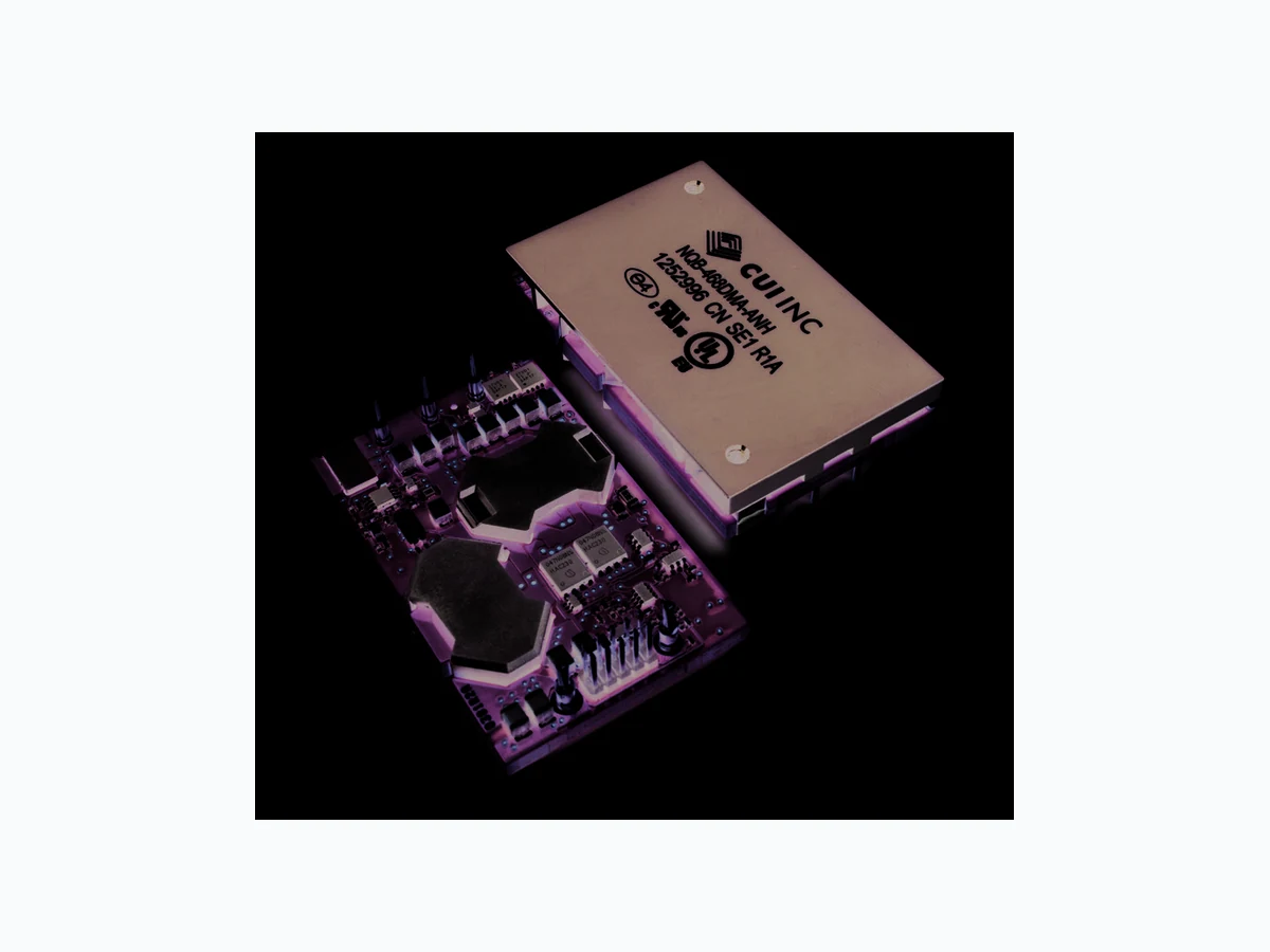
NQB-420DWA-AN CUI
Document overview
- Manufacturer or author: Provided By www.digicamel.com(FREE DATASHEET DOWNLOAD SITE)
- PDF pages: 36
Technical content
cui.com date 02/20/2013 page 1 of 36 SERIES: NQB-D │ DESCRIPTION: FULLY REGULATED ADVANCED BUS CONVERTERS
FEATURES
- quarter-brick with digital PMBus interface 57.9 x 36.8 x 11.3 mm (2.28 x 1.45 x 0.445 in)
- industry standard 5-pins for intermediate bus architectures
- industry-leading power density for telecom and datacom 127~141W / sq. in
- high efficiency, typ. 96.4% at half load,
12 Vout
- fully regulated advanced bus converter from 36~75Vin
- 2,250 Vdc input to output isolation
- fast feed forward regulation to manage line transients
- optional baseplate for high temperature
applications
- droop load sharing with 10% current share accuracy
- PMBus Revision 1.2 compliant
- 2.9 million hours MTBF
- ISO 9001/14001 certified supplier
- Ericsson BMR453 & BMR456 compatible MODEL input voltage output voltage output current output wattage (Vdc) (Vdc) max (A) max (W) NQB-420DWA-AN 36~75 12 35 420 NQB-468DMA-AN 40~60 12 39 468 NQB-415DWB-AN 36~75 12.45 35 415 NQB-462DMB-AN 40~60 12.45 39 462 GENERAL CHARACTERISTICS
- configurable soft start/stop
- precision delay and ramp-up
- voltage margining
- voltage/current/temperature monitoring
- configurable output voltage
- configurable fault response
- power good
cui.com date 02/20/2013 │ page 2 of 36 CUI Inc │ SERIES: NQB-D │ DESCRIPTION: FULLY REGULATED ADVANCED BUS CONVERTERS Nominal Output Voltage: A = 12.0 V B = 12.45 V C = 9.6 V D = 9.0 V E = 5.0 V PART NUMBER KEY NQB- XXX D X X - X X X X - XXX -ES X Input Voltage Range: W = wide (36~75 V) M = medium (40~60 V) Firmware Configuration: 000~ZZZ Base Number Design Output Power: 1~999 Example part number: NQB-420DWA-AN-001
420 W output power, digital pins
wide input voltage range, 12.0 V output 5.33 mm pins, negative enable logic firmware revision 001 Digital Interface Load Sharing Function: D = Vout droop Pin Description: S = SMT Enable Logic Sense: N = negative logic P = positive logic Heatsink Option: "blank" = open frame H = heatsink flat L = heatsink lateral fins T = heatsink transverse fins G = heatsink with GND pin Engineering Sample: ES Engineering Phase: A~Z Packaging: 20 converters(through hole pin)/tray, PE foam dissipative 20 converters(surface mount pin)/tray, Antistatic PPE
CONTENTS
Electrical Specification:
cui.com date 02/20/2013 │ page 3 of 36 CUI Inc │ SERIES: NQB-D │ DESCRIPTION: FULLY REGULATED ADVANCED BUS CONVERTERS General Information Reliability The failure rate (λ) and mean time between failures (MTBF= 1/ λ) is calculated at max output power and an operating ambient temperature (TA) of +40°C. CUI Power Modules uses Telcordia SR-332 Issue 2 Method 1 to calculate the mean steady-state failure rate and standard deviation (σ). Telcordia SR-332 Issue 2 also provides techniques to estimate the upper confidence levels of failure rates based on the mean and standard deviation. Mean steady-state failure rate, λ Std. deviation, σ h/seruliaFn9.06h/seruliaFn124 MTBF (mean value) for the NQB series = 2.9 Mh. MTBF at 90% confidence level = 2.4 Mh Compatibility with RoHS requirements The products are compatible with the relevant clauses and requirements of the RoHS directive 2011/65/EU and have a maximum concentration value of 0.1% by weight in homogeneous materials for lead, mercury, hexavalent chromium, PBB and PBDE and of 0.01% by weight in homogeneous materials for cadmium. Exemptions in the RoHS directive utilized in CUI Power Modules products are found in the Statement of Compliance document. Safety Specification Reliability CUI Power Modules DC/DC converters and DC/DC regulators are designed in accordance with the safety standards IEC 60950 1, EN 60950 1 and UL 60950 1 Safety of Information Technology Equipment. IEC/EN/UL 60950 1 contains requirements to prevent injury or damage due to the following hazards:
- Electrical shock
- Energy hazards
- Fire
- Mechanical and heat hazards
- Radiation hazards
- Chemical hazards On-board DC/DC converters and DC/DC regulators are defined as component power supplies. As components they cannot fully comply with the provisions of any safety requirements without “conditions of acceptability”. Clearance between conductors and between conductive parts of the component power supply and conductors on the board in the final product must meet the applicable safety requirements. Certain conditions of acceptability apply for component power supplies with limited stand-off (see Mechanical Information for further information). It is the responsibility of the installer to ensure that the final product housing these components complies with the requirements of all applicable safety standards and regulations for the final product. Component power supplies for general use should comply with the requirements in IEC/EN/UL 60950 1 Safety of Information Technology Equipment. Product related standards, e.g. IEEE 802.3af Power over Ethernet, and ETS 300132 2 Power interface at the input to telecom equipment, operated by direct current (dc) are based on IEC/EN/UL 60950 1 with regards to safety. CUI Power Modules DC/DC converters and DC/DC regulators are UL 60950 1 recognized and certified in accordance with EN 60950 1. The flammability rating for all construction parts of the products meet requirements for V 0 class material according to IEC 60695 11 10, Fire hazard testing, test flames – 50 W horizontal and vertical flame test methods. Isolated DC/DC converters Galvanic isolation between input and output is verified in an electric strength test and the isolation voltage (Viso) meets the voltage strength requirement for basic insulation according to IEC/EN/UL 60950-1. It is recommended to use a slow blow fuse at the input of each DC/DC converter. If an input filter is used in the circuit the fuse should be placed in front of the input filter. In the rare event of a component problem that imposes a short circuit on the input source, this fuse will provide the following functions:
- Isolate the fault from the input power source so as not to affect the operation of other parts of the system
- Protect the distribution wiring from excessive current and power loss thus preventing hazardous overheating The DC/DC converter output is considered as safety extra low voltage (SELV) if one of the following conditions is met:
- The input source has double or reinforced insulation from the AC mains according to IEC/EN/ UL 60950-1
- The input source has basic or supplementary insulation from the AC mains and the input of the DC/DC converter is maximum 60 Vdc and connected to protective earth according to IEC/EN/UL 60950-1
- The input source has basic or supplementary insulation from the AC mains and the DC/DC converter output is connected to protective earth according to IEC/EN/UL 60950-1 Non - isolated DC/DC regulators The DC/DC regulator output is SELV if the input source meets the requirements for SELV circuits according to IEC/ EN/UL 60950-1.
cui.com date 02/20/2013 │ page 4 of 36 CUI Inc │ SERIES: NQB-D │ DESCRIPTION: FULLY REGULATED ADVANCED BUS CONVERTERS Absolute Maximum Ratings parameter conditions/description min typ max units operating temperature (TP1) see thermal consideration section -40 +125 °C storage temperature (TS) -55 +125 °C input voltage (VI) -0.5 +80 +65* V isolation voltage (Viso) input to output test voltage, see note 1 2250 Vdc input voltage transient (Vtr) according to ETSI EN 300 132-2 and Telcordia GR- 1089-CORE +100 +80* V remote control pin voltage (VRC) see operating information section -0.3 18 V SALERT, CTRL, SCL, SDA, SA0, SA1 (V Logic I/O) -0.3 3.6 V Stress in excess of Absolute Maximum Ratings may cause permanent damage. Absolute Maximum Ratings, sometimes referred to as no destruction limits, are normally tested with one parameter at a time exceeding the limits of Output data or Electrical Characteristics. If exposed to stress above these limits, function and performance may degrade in an unspecified manner. Note 1: Isolation voltage (input/output to base-plate) max 750 Vdc. * Applies for the narrow input version VI= 40-60 V Fundamental Circuit Diagram -IN +IN +OUT -OUT Driver Driver Control RC isolation Auxillary Supply RC
cui.com date 02/20/2013 │ page 5 of 36 CUI Inc │ SERIES: NQB-D │ DESCRIPTION: FULLY REGULATED ADVANCED BUS CONVERTERS Functional Description TP1, TP3 = -40 to +90ºC, VI = 36 to 75 V, sense pins connected to output pins unless otherwise specified under Conditions. Typical values given at: TP1, TP3 = +25°C, VI= 53 V, max IO , unless otherwise specified under Conditions Configuration File: 190 10-CDA 102 0314/001 parameter conditions/description min typ max units PMBus monitoring accuracy input voltage (VIN_READ) -2 ±0.2 2 % output voltage (VOUT_READ) VI = 53V -1.0 ±0.1 1.0 % output current (IOUT_READ) VI = 53V, 50-100% of max IO VI = 53V, 10% of max IO -0.6 ±0.15 6 0.6 A temperature (TEMP_READ) -5 ±3.5 5 ºC fault protection characteristics input under voltage lockout (UVLO) factory default setpoint accuracy hysteresis: factory default hysteresis: configurable via PMBus of threshold range, note 1 delay 300 V V V μs output voltage - under voltage protection (VOUT_UV_FAULT_ LIMIT) factory default configurable via PMBus, note 1 fault response time 200 V V μs output voltage - over voltage protection (VOUT_OV_FAULT_ LIMIT) factory default configurable via PMBus, note 1 fault response time VOUT 15.6 200 V V μs over current protection (OCP) setpoint accuracy (IO) IOUT_OC_FAULT_LIMIT factory default IOUT_OC_FAULT_LIMIT, configurable via PMBus, note 1 fault response time 200 100 A A μs over temperature protection (OTP) OTP_FAULT_LIMIT, factory default OTP_FAULT_LIMIT, configurable via PMBus, note 1 hysteresis, factory default hysteresis, configurable via PMBus, note 1 fault response time -50 125 300 125 125 ºC ºC ºC ºC μs logic input/output characteristics logic input low (VIL) CTRL, SA0, SA1, PG, SCL, SDA 1.1 V logic input high (VIH) CTRL, SA0, SA1, PG, SCL, SDA 2.1 V logic output low (VOL) CTRL, PG, SALERT, SCL, SDA IOL = 6 mA 0.25 V logic output high (VOH) CTRL, PG, SALERT, SCL, SDA IOH = -6 mA 2.7 V bus free time T(BUF) note 2 1.3 μs Note 1: See Operating Information section. 2: PMBus timing parameters according to PMBus spec.
cui.com date 02/20/2013 │ page 6 of 36 CUI Inc │ SERIES: NQB-D │ DESCRIPTION: FULLY REGULATED ADVANCED BUS CONVERTERS Electrical Specification
12.0 V, 35 A, 420 W
TP1, TP3 = -40 to +90ºC, VI = 36 to 75 V, sense pins connected to output pins unless otherwise specified under Conditions. Typical values given at: TP1, TP3 = +25°C, VI = 53 V, max IO, unless otherwise specified under Conditions. Additional Cout = 3.5 mF, Configuration File: 19010-CDA 102 0314/001 parameter conditions/description min typ max units input voltage range (VI) 36 75 V turn-off input voltage (VIoff) decreasing input voltage 32 33 34 V turn-on input voltage (VIon) increasing input voltage 34 35 36 V internal input capacitance (CI) 18 μF output power (PO) 0 420 W efficiency (η) 50% of max IO max IO 50% of max IO, VI = 48 V max IO, VI = 48 V 96.2 95.5 96.4 95.5 power dissipation (Pd) max IO 19.8 29.5 W input idling power (Pli) IO = 0 A, VI = 53 V 3.3 W input standby power (PRC) VI = 53 V (turned off with RC) 0.4 W default switching frequency (fs) 0-100% of max IO 133 140 147 kHz output voltage initial setting and accuracy (VOi) TP1 = +25°C, VI = 53 V, IO = 35 A 11.88 12.0 12.12 V output adjust range (VO) see operating information 4.0 13.2 V output voltage tolerance band (VO) 0-100% of max IO 11.76 12.24 V line regulation (VO) max IO 21 55 mV load regulation (VO) VI = 53 V, 0-100% of max IO 6 40 mV load transient voltage deviation (Vtr) VI = 53 V, load step 25-75-25% of max IO, di/dt = 1 A/μs ±0.4 V load transient recovery time (ttr) VI = 53 V, load step 25-75-25% of max IO, di/dt =
1 A/μs 150 µs
ramp-up time (tr) - (from 10−90% of VOi) 10-100% of max IO, TP1, TP3 = 25ºC, VI = 53 V 8 ms start-up time (ts) - (from VI connection to 90% of VOi) 10-100% of max IO, TP1, TP3 = 25ºC, VI = 53 V 24 ms VI shut-down fall time (tf) - (from VI off to 10% of VO) max IO IO = 0 A, CO = 0 mF 3.6 ms s RC start-up time (tRC) max IO 12 ms RC shut-down fall time (tRC) - (from RC off to 10% of VO) max IO IO = 0 A, CO = 0 mF 5.1 ms s output current (IO) 0 35 A current limit threshold (Ilim) VO = 10.8 V, TP1, TP3 < max TP1, TP3 37 41 44 A short circuit current (Isc) TP1, TP3 = 25ºC, see Note 1 12 A recommended capacitive load (Cout) TP1, TP3 = 25ºC, see Note 2 0.1 3.5 6 mF output ripple & noise (VOac) See ripple & noise section, max IO , see Note 3 60 150 mVp-p over voltage protection (OVP) TP1, TP3 = 25°C, VI = 53 V, 10-100% of max IO 15.6 V remote control (RC) sink current (note 4), see operating information trigger level, decreasing RC-voltage trigger level, increasing RC-voltage 2.6 2.9 0.7 mA V V Note 1: OCP in hic-up mode 2: Low ESR-value 3: Cout = 100 µF, external capacitance 4: Sink current drawn by external device connected to the RC pin. Minimum sink current required guaranteeing activated RC function.
cui.com date 02/20/2013 │ page 7 of 36 CUI Inc │ SERIES: NQB-D │ DESCRIPTION: FULLY REGULATED ADVANCED BUS CONVERTERS Typical Characteristics
12.0 V, 35 A / 420 W
noitapissiD rewoP ycneiciffE 100 05 10 15 20 25 30 35 [A] [%] 36 V 48 V 53 V 75 V 05 10 15 20 25 30 35 [A] [W] 36 V 48 V 53 V 75 V Efficiency vs. load current and input voltage at TP1, TP3 = +25□C Dissipated power vs. load current and input voltage at TP1, TP3 = +25°C Output Characteristics Current Limit Characteristics 11.8 11.9 12.0 12.1 12.2 05 10 15 20 25 30 35 [A] [V] 36 V 48 V 53 V 75 V 3.0 5.0 7.0 9.0 11.0 13.0 35 37 39 41 43 45 [A] [V] 36 V 48 V 53 V 75 V Output voltage vs. load current at TP1, TP3 = +25°C Output voltage vs. load current at IO > max IO , TP1, TP3 = +25°C
cui.com date 02/20/2013 │ page 8 of 36 CUI Inc │ SERIES: NQB-D │ DESCRIPTION: FULLY REGULATED ADVANCED BUS CONVERTERS Typical Characteristics Start-up enabled by connecting VI at: TP1, TP3 = +25°C, VI = 53 V, IO = 35 A resistive load. Top trace: output voltage (5 V/div.). Bottom trace: input voltage (50 V/div.). Time scale: (10 ms/div.). Shut-down enabled by disconnecting VI at: TP1, TP3 = +25°C, VI = 53 V, IO =35 A resistive load. Top trace: output voltage (5 V/div.). Bottom trace: input voltage (50 V/div.). Time scale: (2 ms/div.). esnopseR tneisnarT daoL tuptuO esioN & elppiR tuptuO Output voltage ripple at: TP1, TP3 = +25°C, VI = 53 V, IO = 35 A resistive load. Trace: output voltage (50 mV/div.). Time scale: (2 µs/div.). Output voltage response to load current step-change (8.75-26.25-8.75 A) at: TP1, TP3 =+25°C, VI = 53 V, CO = 3.5 mF. Top trace: output voltage (0.5 V/div.). Bottom trace: output current (20 A/div.). Time scale: (0.5 ms/div.). esnopseR tneisnarT egatloV tupnI Output voltage response to input voltage transient at: TP1, TP3 = +25°C, VI = 36-75 V, IO = 17 A resistive load, CO = 3.5 mF Top trace: output voltage (2 V/div.). Bottom trace: input voltage (20 V/div.). Time scale: (0.5 ms/div.).
cui.com date 02/20/2013 │ page 9 of 36 CUI Inc │ SERIES: NQB-D │ DESCRIPTION: FULLY REGULATED ADVANCED BUS CONVERTERS Typical Characteristics Output Current Derating – Open frame 02 04 06 08 0 100 [°C] [A] 3.0 m/s 2.0 m/s 1.5 m/s 1.0 m/s 0.5 m/s Nat. Conv. Available load current vs. ambient air temperature and airflow at VI = 53 V. See Thermal Consideration section. Output Current Derating – Base plate Thermal Resistance – Base plate 02 04 06 08 01 00 [°C] [A] 3.0 m/s 2.0 m/s 1.5 m/s 1.0 m/s 0.5 m/s Nat. Conv. [°C/W] Available load current vs. ambient air temperature and airflow at VI = 53 V. See Thermal Consideration section. Thermal resistance vs. airspeed measured at the converter. Tested in wind tunnel with airflow and test conditions as per the Thermal consideration section. VI = 53 V. Output Current Derating – Base plate + Heat sink Output Current Derating – Cold wall sealed box 02 04 06 08 01 00 [°C] [A] 3.0 m/s 2.0 m/s 1.5 m/s 1.0 m/s 0.5 m/s Nat. Conv. 02 04 06 08 01 00 [°C] A Tamb 85°C Available load current vs. ambient air temperature and airflow at VI = 53 V. See Thermal Consideration section. Tested with Plate Fin Transverse heatsink, height 0.23 In, P0114 Thermal Pad. Available load current vs. base plate temperature at 85ºC ambient. VI = 53 V. See Thermal Consideration section.
cui.com date 02/20/2013 │ page 10 of 36 CUI Inc │ SERIES: NQB-D │ DESCRIPTION: FULLY REGULATED ADVANCED BUS CONVERTERS Electrical Specification
12.0 V, 39 A / 468 W
TP1, TP3 = -40 to +90ºC, VI = 40 to 60 V, sense pins connected to output pins unless otherwise specified under Conditions. Typical values given at: TP1, TP3 = +25°C, VI = 53 V, max IO, unless otherwise specified under Conditions. Additional Cout = 3.9 mF, Configuration File: 19010-CDA 102 0314/002 Note 1: OCP in hic-up mode 2: Low ESR-value 3: Cout = 100 µF, external capacitance 4: Sink current drawn by external device connected to the RC pin. Minimum sink current required guaranteeing activated RC function. parameter conditions/description min typ max units input voltage range (VI) 40 60 V turn-off input voltage (VIoff) decreasing input voltage 36 37 38 V turn-on input voltage (VIon) increasing input voltage 38 39 40 V internal input capacitance (CI) 18 μF output power (PO) 0 468 W efficiency (η) 50% of max IO max IO 50% of max IO, VI = 48 V max IO, VI = 48 V 96.7 95.7 96.8 95.6 power dissipation (Pd) max IO 21.2 30.5 W input idling power (Pli) IO = 0 A, VI = 53 V 2.8 W input standby power (PRC) VI = 53 V (turned off with RC) 0.4 W default switching frequency (fs) 0-100% of max IO 133 140 147 kHz output voltage initial setting and accuracy (VOi) TP1 = +25°C, VI = 53 V, IO = 39 A 11.88 12.0 12.12 V output adjust range (VO) see operating information 4.0 13.2 V output voltage tolerance band (VO) 0-100% of max IO 11.76 12.24 V line regulation (VO) max IO 31 60 mV load regulation (VO) VI = 53 V, 1-100% of max IO 5 25 mV load transient voltage deviation (Vtr) VI = 53 V, load step 25-75-25% of max IO, di/dt = 1 A/μs ±0.4 V load transient recovery time (ttr) VI = 53 V, load step 25-75-25% of max IO, di/dt = ramp-up time (tr) - (from 10−90% of VOi) 10-100% of max IO, TP1 = 25ºC, VI = 53 V 8 ms start-up time (ts) - (from VI connection to 90% of VOi) 10-100% of max IO, TP1 = 25ºC, VI = 53 V 24 ms VI shut-down fall time (tf) - (from VI off to 10% of VO) max IO IO = 0 A, CO = 0 mF ms s RC start-up time (tRC) max IO 12 ms RC shut-down fall time (tRC) - (from RC off to 10% of VO) max IO IO = 0 A, CO = 0 mF 4.5 ms s output current (IO) 0 39 A current limit threshold (Ilim) VO = 10.8 V, TP1, TP3 < max TP1, TP3 41 44 47 A short circuit current (Isc) TP1 = 25ºC, see Note 1 14 A recommended capacitive load (Cout) TP1 = 25ºC, see Note 2 0.1 3.9 6 mF output ripple & noise (VOac) See ripple & noise section, max IO , see Note 3 50 110 mVp-p over voltage protection (OVP) TP1, TP3 = 25°C, VI = 53 V, 10-100% of max IO 15.6 V remote control (RC) sink current (note 4), see operating information trigger level, decreasing RC-voltage trigger level, increasing RC-voltage 2.6 2.9 0.7 mA V V
cui.com date 02/20/2013 │ page 11 of 36 CUI Inc │ SERIES: NQB-D │ DESCRIPTION: FULLY REGULATED ADVANCED BUS CONVERTERS Typical Characteristics noitapissiD rewoP ycneiciffE 100 05 10 15 20 25 30 35 40 [A] [%] 40 V 48 V 53 V 60 V 05 10 15 20 25 30 35 40 [A] [W] 40 V 48 V 53 V 60 V Efficiency vs. load current and input voltage at TP1, TP3 = +25□C Dissipated power vs. load current and input voltage at TP1, TP3 = +25°C Output Characteristics Current Limit Characteristics 11.8 11.9 12.0 12.1 12.2 05 10 15 20 25 30 35 40 [A] [V] 40 V 48 V 53 V 60 V 3.0 5.0 7.0 9.0 11.0 13.0 39 41 43 45 47 [A] [V] 40 V 48 V 53 V 60 V Output voltage vs. load current at TP1, TP3 = +25°C Output voltage vs. load current at IO > max IO , TP1, TP3 = +25°C
cui.com date 02/20/2013 │ page 12 of 36 CUI Inc │ SERIES: NQB-D │ DESCRIPTION: FULLY REGULATED ADVANCED BUS CONVERTERS Typical Characteristics Start-up enabled by connecting VI at: TP1, TP3 = +25°C, VI = 53 V, IO = 39 A resistive load. Top trace: output voltage (5 V/div.). Bottom trace: input voltage (50 V/div.). Time scale: (10 ms/div.). Shut-down enabled by disconnecting VI at: TP1, TP3 = +25°C, VI = 53 V, IO =39 A resistive load. Top trace: output voltage (5 V/div.). Bottom trace: input voltage (50 V/div.). Time scale: (2 ms/div.). esnopseR tneisnarT daoL tuptuO esioN & elppiR tuptuO Output voltage ripple at: TP1, TP3 = +25°C, VI = 53 V, IO = 39 A resistive load. Trace: output voltage (50 mV/div.). Time scale: (2 µs/div.). Output voltage response to load current step-change (9.75-29.25-9.75 A) at: TP1, TP3 =+25°C, VI = 53 V, CO = 3.9 mF. Top trace: output voltage (0.5 V/div.). Bottom trace: output current (20 A/div.). Time scale: (0.5 ms/div.). esnopseR tneisnarT egatloV tupnI Output voltage response to input voltage transient at: TP1, TP3 = +25°C, VI = 40-60 V, IO = 19,5 A resistive load, CO = 3.9 mF Top trace: output voltage (2 V/div.). Bottom trace: input voltage (20 V/div.). Time scale: (0.5 ms/div.).
cui.com date 02/20/2013 │ page 13 of 36 CUI Inc │ SERIES: NQB-D │ DESCRIPTION: FULLY REGULATED ADVANCED BUS CONVERTERS Typical Characteristics Output Current Derating – Open frame 02 04 06 08 01 00 [°C] [A] 3.0 m/s 2.0 m/s 1.5 m/s 1.0 m/s 0.5 m/s Nat. Conv. Available load current vs. ambient air temperature and airflow at VI = 53 V. See Thermal Consideration section. Output Current Derating – Base plate Thermal Resistance – Base plate 02 04 06 08 01 00 [°C] [A] 3.0 m/s 2.0 m/s 1.5 m/s 1.0 m/s 0.5 m/s Nat. Conv. [°C/W] Available load current vs. ambient air temperature and airflow at VI = 53 V. See Thermal Consideration section. Thermal resistance vs. airspeed measured at the converter. Tested in wind tunnel with airflow and test conditions as per the Thermal consideration section. VI = 53 V. Output Current Derating – Base Plate + Heat sink Output Current Derating – Cold wall sealed box 02 04 06 08 01 00 [°C] [A] 3.0 m/s 2.0 m/s 1.5 m/s 1.0 m/s 0.5 m/s Nat. Conv. 02 04 06 08 01 00 [°C] A Tamb 85°C Available load current vs. ambient air temperature and airflow at VI = 53 V. See Thermal Consideration section. Tested with Plate Fin Transverse heatsink, height 0.23 In, P0114 Thermal Pad. Available load current vs. base plate temperature at 85ºC ambient. VI = 53 V. See Thermal Consideration section.
cui.com date 02/20/2013 │ page 14 of 36 CUI Inc │ SERIES: NQB-D │ DESCRIPTION: FULLY REGULATED ADVANCED BUS CONVERTERS Electrical Specification
12.45 V, 35 A / 415 W
TP1, TP3 = -40 to +90ºC, VI = 36 to 75 V, sense pins connected to output pins unless otherwise specified under Conditions. Typical values given at: TP1, TP3 = +25°C, VI = 53 V, max IO, unless otherwise specified under Conditions. Additional Cout = 3.9 mF, Configuration File: 19010-CDA 102 0314/014 Note 1: OCP in hic-up mode 2: Low ESR-value 3: Cout = 100 µF, external capacitance 4: Sink current drawn by external device connected to the RC pin. Minimum sink current required guaranteeing activated RC function. parameter conditions/description min typ max units input voltage range (VI) 36 75 V turn-off input voltage (VIoff) decreasing input voltage 32 33 34 V turn-on input voltage (VIon) increasing input voltage 34 35 36 V internal input capacitance (CI) 18 μF output power (PO) 0 415 W efficiency (η) 50% of max IO max IO 50% of max IO, VI = 48 V max IO, VI = 48 V 96.2 95.5 96.4 95.5 power dissipation (Pd) max IO 19.5 29.5 W input idling power (Pli) IO = 0 A, VI = 53 V 3.2 W input standby power (PRC) VI = 53 V (turned off with RC) 0.4 W default switching frequency (fs) 0-100% of max IO 133 140 147 kHz output voltage initial setting and accuracy (VOi) TP1 = 25°C, VI = 53 V, IO = 0 A 12.415 12.45 12.485 V output adjust range (VO) see operating information 4.0 13.2 V output voltage tolerance band (VO) 0-100% of max IO 11.5 12.7 V line regulation (VO) max IO 20 55 mV load regulation (VO) VI = 53 V, 0-100% of max IO 500 600 700 mV load transient voltage deviation (Vtr) VI = 53 V, load step 25-75-25% of max IO, di/dt = 1 A/μs ±0.4 V load transient recovery time (ttr) VI = 53 V, load step 25-75-25% of max IO, di/dt = ramp-up time (tr) - (from 10−90% of VOi) 10-100% of max IO, TP1, TP3 = 25ºC, VI = 53 V 23 ms start-up time (ts) - (from VI connection to 90% of VOi) 10-100% of max IO, TP1, TP3 = 25ºC, VI = 53 V 39 ms VI shut-down fall time (tf) - (from VI off to 10% of VO) max IO IO = 0 A, CO = 0 mF 3.6 ms s RC start-up time (tRC) max IO 27 ms RC shut-down fall time (tRC) - (from RC off to 10% of VO) max IO IO = 0 A, CO = 0 mF 5.1 ms s output current (IO) 0 35 A current limit threshold (Ilim) VO = 10.8 V, TP1, TP3 < max TP1, TP3 37 41 44 A short circuit current (Isc) TP1, TP3 = 25ºC, see Note 1 12 A recommended capacitive load (Cout) TP1, TP3 = 25ºC, see Note 2 0.1 3.5 6 mF output ripple & noise (VOac) See ripple & noise section, max IO , see Note 3 60 150 mVp-p over voltage protection (OVP) TP1, TP3 = 25°C, VI = 53 V, 10-100% of max IO 15.6 V remote control (RC) sink current (note 4), see operating information trigger level, decreasing RC-voltage trigger level, increasing RC-voltage 2.6 2.9 0.7 mA V V
cui.com date 02/20/2013 │ page 15 of 36 CUI Inc │ SERIES: NQB-D │ DESCRIPTION: FULLY REGULATED ADVANCED BUS CONVERTERS Typical Characteristics
12.45 V, 63 A / 747 W, two products in parallel
noitapissiD rewoP ycneiciffE 100 01 02 03 04 05 06 0[ A] [%] 36 V 48 V 53 V 75 V 01 02 03 04 05 06 0[ A] [W] 36 V 48 V 53 V 75 V Efficiency vs. load current and input voltage at TP1, TP3 = +25□C Dissipated power vs. load current and input voltage at TP1, TP3 = +25°C Output Characteristics Current Limit Characteristics 11.8 11.9 12.0 12.1 12.2 12.3 12.4 12.5 01 02 03 04 05 06 0[ A] [V] 36 V 48 V 53 V 75 V 3.0 5.0 7.0 9.0 11.0 13.0 63 65 67 69 71 73 75 77 79 81 83 [A] [V] 36 V 48 V 53 V 75 V Output voltage vs. load current at TP1, TP3 = +25°C Output voltage vs. load current at IO > max IO , TP1, TP3 = +25°C Start-up Output Load Transient Response Start-up enabled by connecting VI at: TP1, TP3 = +25°C, VI = 53 V, IO = 63 A resistive load. Top trace: output voltage (5 V/div.). Bottom trace: input voltage (50 V/div.). Time scale: (10 ms/div.). Output voltage response to load current step-change (15.8-47.3-15.8 A) at: TP1, TP3 =+25°C, VI = 53 V, CO = 3.5 mF. Top trace: output voltage (0.5 V/div.). Bottom trace: output current (20 A/div.). Time scale: (0.5 ms/div.).
cui.com date 02/20/2013 │ page 16 of 36 CUI Inc │ SERIES: NQB-D │ DESCRIPTION: FULLY REGULATED ADVANCED BUS CONVERTERS Typical Characteristics Output Current Derating – Open frame 02 04 06 08 01 00 [°C] [A] 3.0 m/s 2.0 m/s 1.5 m/s 1.0 m/s 0.5 m/s Nat. Conv. Available load current vs. ambient air temperature and airflow at VI = 53 V. See Thermal Consideration section. Output Current Derating – Base plate Thermal Resistance – Base plate 02 04 06 08 01 00 [°C] [A] 3.0 m/s 2.0 m/s 1.5 m/s 1.0 m/s 0.5 m/s Nat. Conv. [°C/W] Available load current vs. ambient air temperature and airflow at VI = 53 V. See Thermal Consideration section. Thermal resistance vs. airspeed measured at the converter. Tested in wind tunnel with airflow and test conditions as per the Thermal consideration section. VI = 53 V. Output Current Derating – Base plate + Heat sink Output Current Derating – Cold wall sealed box 02 04 06 08 0 100 [°C] [A] 3.0 m/s 2.0 m/s 1.5 m/s 1.0 m/s 0.5 m/s Nat. Conv. 02 04 06 08 01 00 [°C] A Tamb 85°C Available load current vs. ambient air temperature and airflow at VI = 53 V. See Thermal Consideration section. Tested with Plate Fin Transverse heatsink, height 0.23 In, P0114 Thermal Pad. Available load current vs. base plate temperature at 85ºC ambient. VI = 53 V. See Thermal Consideration section.
cui.com date 02/20/2013 │ page 17 of 36 CUI Inc │ SERIES: NQB-D │ DESCRIPTION: FULLY REGULATED ADVANCED BUS CONVERTERS Electrical Specification
12.45 V, 39 A / 462 W
TP1, TP3 = -40 to +90ºC, VI = 40 to 60 V, sense pins connected to output pins unless otherwise specified under Conditions. Typical values given at: TP1, TP3 = +25°C, VI = 53 V, max IO, unless otherwise specified under Conditions. Additional Cout = 3.9 mF, Configuration File: 19010-CDA 102 0314/017 Note 1: OCP in hic-up mode 2: Low ESR-value 3: Cout = 100 µF, external capacitance 4: Sink current drawn by external device connected to the RC pin. Minimum sink current required guaranteeing activated RC function. parameter conditions/description min typ max units input voltage range (VI) 40 60 V turn-off input voltage (VIoff) decreasing input voltage 36 37 38 V turn-on input voltage (VIon) increasing input voltage 38 39 40 V internal input capacitance (CI) 18 μF output power (PO) 0 462 W efficiency (η) 50% of max IO max IO 50% of max IO, VI = 48 V max IO, VI = 48 V 96.7 95.7 96.8 95.6 power dissipation (Pd) max IO 21.0 30.5 W input idling power (Pli) IO = 0 A, VI = 53 V 2.8 W input standby power (PRC) VI = 53 V (turned off with RC) 0.4 W default switching frequency (fs) 0-100% of max IO 133 140 147 kHz output voltage initial setting and accuracy (VOi) TP1 = 25°C, VI = 53 V, IO = 0 A 12.415 12.45 12.485 V output adjust range (VO) see operating information 4.0 13.2 V output voltage tolerance band (VO) 0-100% of max IO 11.5 12.7 V line regulation (VO) max IO 31 60 mV load regulation (VO) VI = 53 V, 0-100% of max IO 500 600 700 mV load transient voltage deviation (Vtr) VI = 53 V, load step 25-75-25% of max IO, di/dt = 1 A/μs ±0.4 V load transient recovery time (ttr) VI = 53 V, load step 25-75-25% of max IO, di/dt = ramp-up time (tr) - (from 10−90% of VOi) 10-100% of max IO, TP1 = 25ºC, VI = 53 V 23 ms start-up time (ts) - (from VI connection to 90% of VOi) 10-100% of max IO, TP1 = 25ºC, VI = 53 V 39 ms VI shut-down fall time (tf) - (from VI off to 10% of VO) max IO IO = 0 A, CO = 0 mF ms s RC start-up time (tRC) max IO 27 ms RC shut-down fall time (tRC) - (from RC off to 10% of VO) max IO IO = 0 A, CO = 0 mF 4.5 ms s output current (IO) 0 39 A current limit threshold (Ilim) VO = 10.8 V, TP1, TP3 < max TP1, TP3 41 44 47 A short circuit current (Isc) TP1 = 25ºC, see Note 1 14 A recommended capacitive load (Cout) TP1 = 25ºC, see Note 2 0.1 3.9 6 mF output ripple & noise (VOac) See ripple & noise section, max IO , see Note 3 50 110 mVp-p over voltage protection (OVP) TP1, TP3 = 25°C, VI = 53 V, 10-100% of max IO 15.6 V remote control (RC) sink current (note 4), see operating information trigger level, decreasing RC-voltage trigger level, increasing RC-voltage 2.6 2.9 0.7 mA V V
cui.com date 02/20/2013 │ page 18 of 36 CUI Inc │ SERIES: NQB-D │ DESCRIPTION: FULLY REGULATED ADVANCED BUS CONVERTERS Typical Characteristics
12.45 V, 70 A / 830 W, two products in parallel
noitapissiD rewoP ycneiciffE 100 01 02 03 04 05 06 07 0[ A] [%] 40 V 48 V 53 V 60 V 01 02 03 04 05 06 07 0 [A] [W] 40 V 48 V 53 V 60 V Efficiency vs. load current and input voltage at TP1, TP3 = +25□C Dissipated power vs. load current and input voltage at TP1, TP3 = +25°C Output Characteristics Current Limit Characteristics 11.8 11.9 12.0 12.1 12.2 12.3 12.4 12.5 01 02 03 04 05 06 07 0[ A] [V] 40 V 48 V 53 V 60 V 3.0 5.0 7.0 9.0 11.0 13.0 70 75 80 85 90 [A] [V] 40 V 48 V 53 V 60 V Output voltage vs. load current at TP1, TP3 = +25°C Output voltage vs. load current at IO > max IO , TP1, TP3 = +25°C Start-up Output Load Transient Response Start-up enabled by connecting VI at: TP1, TP3 = +25°C, VI = 53 V, IO = 70 A resistive load. Top trace: output voltage (5 V/div.). Bottom trace: input voltage (50 V/div.). Time scale: (10 ms/div.). Output voltage response to load current step-change (17.5-52.5-17.5 A) at: TP1, TP3 =+25°C, VI = 53 V, CO = 3.9 mF Top trace: output voltage (0.5 V/div.). Bottom trace: output current (20 A/div.). Time scale: (0.5 ms/div.).
cui.com date 02/20/2013 │ page 19 of 36 CUI Inc │ SERIES: NQB-D │ DESCRIPTION: FULLY REGULATED ADVANCED BUS CONVERTERS Typical Characteristics Output Current Derating – Open frame 02 04 06 08 0 100 [°C] [A] 3.0 m/s 2.0 m/s 1.5 m/s 1.0 m/s 0.5 m/s Nat. Conv. Available load current vs. ambient air temperature and airflow at VI = 53 V. See Thermal Consideration section. Output Current Derating – Base plate Thermal Resistance – Base plate 02 04 06 08 01 00 [°C] [A] 3.0 m/s 2.0 m/s 1.5 m/s 1.0 m/s 0.5 m/s Nat. Conv. [°C/W] Available load current vs. ambient air temperature and airflow at VI = 53 V. See Thermal Consideration section. Thermal resistance vs. airspeed measured at the converter. Tested in wind tunnel with airflow and test conditions as per the Thermal consideration section. VI = 53 V. Output Current Derating – Base Plate + Heat sink Output Current Derating – Cold wall sealed box 02 04 06 08 01 00 [°C] [A] 3.0 m/s 2.0 m/s 1.5 m/s 1.0 m/s 0.5 m/s Nat. Conv. 02 04 06 08 01 00 [°C] A Tamb 85°C Available load current vs. ambient air temperature and airflow at VI = 53 V. See Thermal Consideration section. Tested with Plate Fin Transverse heatsink, height 0.23 In, P0114 Thermal Pad. Available load current vs. base plate temperature at 85ºC ambient. VI = 53 V. See Thermal Consideration section.
cui.com date 02/20/2013 │ page 20 of 36 CUI Inc │ SERIES: NQB-D │ DESCRIPTION: FULLY REGULATED ADVANCED BUS CONVERTERS EMC Specification Conducted EMI Input terminal value (typ) Conducted EMI measured according to EN55022, CISPR 22 and FCC part 15J (see test set-up). The fundamental switching frequency is 140 kHz for NQB at VI = 53 V, max IO. EMI without filter Suggested external input filter in order to meet class B in EN 55022, CISPR 22 and FCC part 15J. Optional external filter for class B C1 C2 C3 R Module Filter components: C1 = 1 μF C2 = 1 μF+220 μF C3 = 1 μF+220 μF C4,C5 = 2.2 nF L1 = 810 μH L2 = 810 μH EMI with filter Test set-up The radiated EMI performance of the product will depend on the PWB layout and ground layer design. It is also important to consider the stand-off of the product. If a ground layer is used, it should be connected to the output of the product and the equipment ground or chassis. A ground layer will increase the stray capacitance in the PWB and improve the high frequency EMC performance. Layout recommendations Output ripple and noise measured according to figure below. Output ripple and noise Output ripple and noise test setup
cui.com date 02/20/2013 │ page 21 of 36 CUI Inc │ SERIES: NQB-D │ DESCRIPTION: FULLY REGULATED ADVANCED BUS CONVERTERS Operating information This product is equipped with a PMBus interface. The product incorporates a wide range of readable and configurable power management features that are simple to implement with a minimum of external components. Additionally, the product includes protection features that continuously safeguard the load from damage due to unexpected system faults. A fault is also shown as an alert on the SALERT pin. The following product parameters can continuously be monitored by a host: Input voltage, output voltage/current, duty cycle and internal temperature. The product is delivered with a default configuration suitable for a wide range operation in terms of input voltage, output voltage, and load. The configuration is stored in an internal Non-Volatile Memory (NVM). All power management functions can be reconfigured using the PMBus interface. Please contact your local CUI Power Modules representative for design support of custom configurations or appropriate SW tools for design and down-load of your own configurations. Power Management Overview The NQB consists of two different product families designed for two different input voltage ranges, 36 to 75 Vdc and 40 to 60 Vdc, see ordering information. The input voltage range 36 to 75 Vdc meets the requirements of the European Telecom Standard ETS 300 132-2 for normal input voltage range in –48 and –60 Vdc systems, -40.5 to -57.0 V and –50.0 to -72 V respectively. At input voltages exceeding 75 V, the power loss will be higher than at normal input voltage and TP1 must be limited to absolute max +125°C. The absolute maximum continuous input voltage is 80 Vdc. The input voltage range 40 to 60 Vdc meets the requirements for normal input voltage range in -48 V systems, -40.5 to -57.0 V. At input voltages exceeding
60 V, the power loss will be higher than at normal input
voltage and TP1 must be limited to absolute max +125°C. The absolute maximum continuous input voltage is 65 Vdc. Input Voltage The product monitors the input voltage and will turn on and turn off at predetermined levels. The minimum hysteresis between turn on and turn off input voltage is 2 V. The turn on and turn off levels of the product can be reconfigured using the PMBus interface Turn-off Input Voltage The products are fitted with a configurable remote control function. The primary remote control is referenced to the primary negative input connection (-In). The RC function allows the converter to be turned on/off by an external device like a semiconductor or mechanical switch. The RC pin has an internal pull up resistor. The remote control functions can also be configured using the PMBus. Remote Control (RC) The device should be capable of sinking 0.7 mA. When the RC pin is left open, the voltage generated on the RC pin is max 6 V. The standard product is provided with “negative logic” remote control and will be off until the RC pin is connected to the -In. To turn on the product the voltage between RC pin and -In should be less than 1 V. To turn off the product the RC pin should be left open for a minimum of time 150 µs, the same time requirement applies when the product shall turn on. In situations where it is desired to have the product to power up automatically without the need for control signals or a switch, the RC pin can be wired directly to –In or disabled via the 0xE3 command. The logic option for the primary remote control is configured via 0xE3 command using the PMBus. The CTRL-pin can be configured as remote control via the PMBus interface. In the default configuration the CTRL- pin is disabled and floating. The output can be configured to internal pull-up to 3.3 V using the MFR_MULTI_PIN_ CONFIG (0xF9) PMBus command. The CTRL-pin can be left open when not used. The logic options for the secondary remote control can be positive or negative logic. The logic option for the secondary remote control is configured via ON_OFF_CONFIG (0x02) command using the PMBus interface, see also MFR_MULTI_PIN_CONFIG section. Remote Control (secondary side) The impedance of both the input source and the load will interact with the impedance of the product. It is important that the input source has low characteristic impedance. Minimum recommended external input capacitance is 100 µF. The performance in some applications can be enhanced by addition of external capacitance as described under External Decoupling Capacitors. Input and Output Impedance When powering loads with significant dynamic current requirements, the voltage regulation at the point of load can be improved by addition of decoupling capacitors at the load. The most effective technique is to locate low ESR ceramic and electrolytic capacitors as close to the load as possible, using several parallel capacitors to lower the effective ESR. The ceramic capacitors will handle high- frequency dynamic load changes while the electrolytic capacitors are used to handle low frequency dynamic load changes. Ceramic capacitors will also reduce any high frequency noise at the load. It is equally important to use low resistance and low inductance PWB layouts and cabling. External decoupling capacitors will become part of the product’s control loop. The control loop is optimized for a wide range of external capacitance and the maximum recommended value that could be used without any additional analysis is found in the electrical specification. The ESR of the capacitors is a very important parameter. Stable operation is guaranteed with a verified ESR value of External Decoupling Capacitors
cui.com date 02/20/2013 │ page 22 of 36 CUI Inc │ SERIES: NQB-D │ DESCRIPTION: FULLY REGULATED ADVANCED BUS CONVERTERS >10 mΩ across the output connections. For further information please contact your local CUI Power Modules representative. The NQB, DLS products are variants that can be connected in parallel. The products have a pre-configured voltage droop: The stated output voltage set point is at no load. The output voltage will decrease when the load current is increased. The voltage will droop 0.6 V while load reaches max load. This feature allows the products to be connected in parallel and share the current with 10% accuracy. Up to 90% of max output current can be used from each product. When running DLS-products in parallel command (0xF9) must be set according to MFR_MULTI_PIN_CONFIG. To prevent unnecessary current stress, changes of the output voltage must be done with the output disabled. This must be considered for all commands that affect the output voltage. Parallel Operation (Droop Load Share, DLS) Voltage regulation DLS products 11.6 11.8 12.0 12.2 12.4 12.6 12.8 01 02 03 04 05 06 07 0 Output Current [A] Output Voltage [V] Module 1 Module 2 Module 1+2 The NQB products have a feed forward function implemented that can handle sudden input voltage changes. The output voltage will be regulated during an input transient and will typically stay within 10% when an input transient is applied. Feed Forward Capability The product provides a PMBus digital interface that enables the user to configure many aspects of the device operation as well as monitor the input and output parameters. Please contact your local CUI Power Modules representative for appropriate SW tools to down-load new configurations. PMBus configuration and support The output voltage of the product can be reconfigured using the PMBus interface. Output Voltage Adjust using PMBus These controls allow the output voltage to be momentarily adjusted, either up or down, by a nominal 10%. This provides a convenient method for dynamically testing the operation of the load circuit over its supply margin or range. It can also be used to verify the function of supply voltage supervisors. The margin up and down levels of the product can be re- configured using the PMBus interface. Margin Up/Down Controls The default rise time of the ramp up is 10 ms. When starting by applying input voltage the control circuit boot- up time adds an additional 15 ms delay. The soft-start power up of the product can be reconfigured using the PMBus interface. The DLS variants have a pre-configured ramp up time of 25 ms. Soft-start Power Up The product has remote sense that can be used to compensate for voltage drops between the output and the point of load. The sense traces should be located close to the PWB ground layer to reduce noise susceptibility. The remote sense circuitry will compensate for up to 10% voltage drop between output pins and the point of load. If the remote sense is not needed +Sense should be connected to +Out and -Sense should be connected to -Out. To be able to use remote sense the converter must be equipped with a Communication interface. Remote Sense The products are protected from thermal overload by an internal temperature shutdown protection. When TP1 as defined in thermal consideration section is exceeded the product will shut down. The product will make continuous attempts to start up (non-latching mode) and resume normal operation automatically when the temperature has dropped below the temperature threshold set in the command OT_WARN_LIMIT (0x51); the hysteresis is defined in general electrical specification. The OTP and hysteresis of the product can be re-configured using the PMBus interface. The product has also an under temperature protection. The OTP and UTP fault limit and fault response can be configured via the PMBus. Note: using the fault response “continue without interruption” may cause permanent damage to the product Temperature Protection (OTP, UTP) The product includes over voltage limiting circuitry for protection of the load. The default OVP limit is 30% above the nominal output voltage. If the output voltage exceeds the OVP limit, the product can respond in different ways. The default response from an over voltage fault is to immediately shut down. The device will continuously check for the presence of the fault condition, and when the fault condition no longer exists the device will be re-enabled. The OVP fault level and fault response can be re- configured using the PMBus interface. Over Voltage Protection (OVP)
cui.com date 02/20/2013 │ page 23 of 36 CUI Inc │ SERIES: NQB-D │ DESCRIPTION: FULLY REGULATED ADVANCED BUS CONVERTERS The product includes current limiting circuitry for protection at continuous overload. The default setting for the product is hic-up mode if the maximum output current is exceeded and the output voltage is below 0.3×Vout, set in command IOUT_OC_LV_FAULT_LIMIT (0x48). Above the trip voltage value in command 0x48 the product will continue operate while maintaining the output current at the value set by IOUT_OC_FAULT_LIMIT (0x46). The load distribution should be designed for the maximum output short circuit current specified. Droop Load Share variants (DLS) will enter hic-up mode, with a trip voltage, 0.04×Vout, set in command IOUT_ OC_LV_FAULT_LIMIT (0x48). Above the trip voltage in command (0x48) the product will continue operate while maintaining the output current at the value set by IOUT_ OC_FAULT_LIMIT (0x46). The over current protection of the product can be reconfigured using the PMBus interface. Over Current Protection (OCP) The input of the product can be protected from high input voltage and low input voltage. The over/under-voltage fault level and fault response can be configured via the PMBus interface. Input Over/Under voltage protection The product has a Pre-bias start up functionality and will not sink current during start up if a Pre-bias source is present at the output terminals. If the Pre-bias voltage is lower than the target value set in VOUT_COMMAND (0x21), the product will ramp up to the target value. If the Pre-bias voltage is higher than the target value set in VOUT_COMMAND (0x21), the product will ramp down to the target value and in this case sink current for a limited of time set in the command TOFF_MAX_WARN_LIMIT (0x66). Pre-bias Start-up Capability The product provides Power Good (PG) flag in the Status Word register that indicates the output voltage is within a specified tolerance of its target level and no fault condition exists. If specified in section Connections, the product also provides a PG signal output. The Power Good signal is by default configured as active low, Push-pull and can be re-configured via the PMBus interface. The Power Good output can be configured as Push-pull or “High Z when active” to permit AND’ing of parallel devices. It is not recommended to use Push-pull when paralleling PG-pins, see MFR_MULTI_PIN_CONFIG. Power Good This product does not support synchronization, tracking or external reference. Synchronization, Tracking and External reference The switching frequency is set to 140 kHz as default but this can be reconfigured via the PMBus interface. The product is optimized at this frequency but can run at lower and higher frequency, (125-150 kHz). The electrical performance can be affected if the switching frequency is changed. Switching frequency adjust using PMBus The MFR_MULTI_PIN_CONFIG (0xF9) command enables or disables different functions inside the product. This command can be configured according to the table for different functions. MFR_MULTI_PIN_CONFIG Bit 7:6 00 = Stand alone 01 = Slave (N/A) 10 = DLS 11 = Master (N/A) 1 1 1 1 1 1 0 0 0 0 0 0 0 0 0 0 0 0 0 0 0 0 0 0 Bit 5 Power Good High Z when active 0 0 0 0 1 1 0 0 0 0 1 1 Bit 4 Tracking enable (N/A) 0 0 0 0 0 0 0 0 0 0 0 0 Bit 3 External reference (N/A) 0 0 0 0 0 0 0 0 0 0 0 0 Bit 2 Power Good Enable 0 0 1 1 1 1 0 0 1 1 1 1 Bit 1 Reserved 1 1 1 1 1 1 0 0 0 0 0 0 Bit 0 Secondary Remote Control Pull up/down resistor enable 1) 0 1 0 1 0 1 0 1 0 1 0 1 1) When not used with PMBus, the CTRL input can be internally pulled up or down depending on if it is active high or low. When active low it will be pulled up and vice versa DLS, PMBus Control (0x82) DLS, Sec RC w/ pull up/down (0x83) DLS, Power Good Push-pull, PMBus Control (0x86) DLS, Power Good Push-pull, Sec RC w/ pull up/down (0x87) DLS, Power Good High Z when active, PMBus Control (0xA6) DLS, Power Good High Z when active, Sec RC w/ pull up/down (0xA7) Stand alone, PMBus Control (0x00) Stand alone, Sec RC w/ pull up/down (0x01) Stand alone, Power Good Push-pull, PMBus Control (0x04) Stand alone, Power Good Push-pull, Sec RC w/ pull up/down (0x05) Stand alone, Power Good High Z when active, PMBus Control (0x24) Stand alone, Power Good High Z when active, Sec RC w/ pull up/down (0x25) The MFR_MULTI_PIN_CONFIG can be reconfigured using the PMBus interface. Default configuration is set to Power Good Push-Pull (0x04) for stand alone variants and DLS Power Good Push-Pull (0x86) for Droop Load Share variants. This product has two data storage set: Default data (CUI factory) and User data. The User data set’s priority is higher than the Default data. The User data area is empty while shipped to customer. After boot-up, if the controller found no data stored in User data area, it will load Default data instead. Customer can change the RAM data and store the changes into flash memory by PMBUS Store_User_All, next power cycle will load the User data into RAM for execute. Store_Default_All is write protected to ensure the factory settings is always available for recovery. User customized settings
cui.com date 02/20/2013 │ page 24 of 36 CUI Inc │ SERIES: NQB-D │ DESCRIPTION: FULLY REGULATED ADVANCED BUS CONVERTERS The NQB products are designed to be fully regulated within the plotted area. Operating outside this area is not recommended. Output Voltage Regulation 12.0 12.2 12.4 12.6 12.8 13.0 13.2 13.4 35 45 55 65 75 Vin [V] Vout [V] Vin range: 36-75Vdc 12.0 12.2 12.4 12.6 12.8 13.0 13.2 13.4 35 40 45 50 55 60 65 Vin [V] Vout [V] Vin range:40-60Vdc Thermal Consideration The product is designed to operate in different thermal environments and sufficient cooling must be provided to ensure reliable operation. For products mounted on a PWB without a heat sink attached, cooling is achieved mainly by conduction, from the pins to the host board, and convection, which is dependant on the airflow across the product. Increased airflow enhances the cooling of the product. The Output Current Derating graph found in the output section for each model provides the available output current vs. ambient air temperature and air velocity at VI =53 V. The product is tested on a 254 x 254 mm, 35 µm (1 oz), 16-layer test board mounted vertically in a wind tunnel with a cross-section of 608 x 203 mm. General For products with base plate used in a sealed box/cold wall application, cooling is achieved mainly by conduction through the cold wall. The Output Current Derating graphs are found in the output section for each model. The product is tested in a sealed box test set up with ambient temperatures 85, 55 and 25°C. The product operating temperature is used to monitor the temperature of the product, and proper thermal conditions can be verified by measuring the temperature at positions P1, P2, P3 and P4. The temperature at these positions (TP1, TP2, TP3, TP4) should not exceed the maximum temperatures in the table below. The number of measurement points may vary with different thermal design and topology. Temperatures above maximum TP1, measured at the reference point P1 (TP3 / P3 for base plate versions) are not allowed and may cause permanent damage. Definition of product operating temperature Position Description Max temperature P1 PWB (reference point, open frame) TP1=125º C P2 Opto-coupler TP2=105º C P3 PWB (reference point for base-plate version) TP3=125º C P4 Primary MOSFET TP4=125º C
cui.com date 02/20/2013 │ page 25 of 36 CUI Inc │ SERIES: NQB-D │ DESCRIPTION: FULLY REGULATED ADVANCED BUS CONVERTERS Top view Bottom view For products with base plate the maximum allowed ambient temperature can be calculated by using the thermal resistance. 1. The power loss is calculated by using the formula ((1/η) - 1) × output power = power losses (Pd). η = efficiency of product. E.g. 95 % = 0.95 2. Find the thermal resistance (Rth) in the Thermal Resistance graph found in the Output section for each model. Note that the thermal resistance can be significantly reduced if a heat sink is mounted on the top of the base plate. Calculate the temperature increase (ΔT). ΔT = Rth x Pd 3. Max allowed ambient temperature is: Max TP1 - ΔT. E.g. NQB-468 at 2m/s: 3. 125 °C - 69.0°C = max ambient temperature is 56°C The actual temperature will be dependent on several factors such as the PWB size, number of layers and direction of airflow. Ambient Temperature Calculation (Best air flow direction is from positive to negative pins.) Connections (Top view) Pin Designation Function 1 +In Positive Input
2 RC Remote Control
3 Case Case to GND (optional)
6 S+ Positive Remote Sense
7 S- Negative Remote Sense
8 SA0 Address pin 0
9 SA1 Address pin 1
10 SCL PMBus Clock
11 SDA PMBus Data
12 PG Power Good output
13 DGND PMBus ground
14 SALERT PMBus alert signal
15 CTRL PMBus remote control
cui.com date 02/20/2013 │ page 26 of 36 CUI Inc │ SERIES: NQB-D │ DESCRIPTION: FULLY REGULATED ADVANCED BUS CONVERTERS This product provides a PMBus digital interface that enables the user to configure many aspects of the device operation as well as to monitor the input and output voltages, output current and device temperature. The product can be used with any standard two-wire I2C or SMBus host device. In addition, the product is compatible with PMBus version 1.2 and includes an SALERT line to help mitigate bandwidth limitations related to continuous fault monitoring. The product supports 100 kHz and 400 kHz bus clock frequency only. The PMBus signals, SCL, SDA and SALERT require passive pull-up resistors as stated in the SMBus Specification. Pull-up resistors are required to guarantee the rise time as follows: Eq. 7 where Rp is the pull-up resistor value and Cp is the bus load. The maximum allowed bus load is 400 pF. The pull- up resistor should be tied to an external supply between 2.7 to 5.5 V, which should be present prior to or during power-up. If the proper power supply is not available, voltage dividers may be applied. Note that in this case, the resistance in the equation above corresponds to parallel connection of the resistors forming the voltage divider. It is recommended to always use PEC (Packet Error Check) when communicating via PMBus. For these products it is a requirement to use PEC when using Send Byte to the device, for example command “RESTORE_DEFAULT_ALL”. Monitoring via PMBus PMBus Interface A system controller (host device) can monitor a wide variety of parameters through the PMBus interface. The controller can monitor fault conditions by monitoring the SALERT pin, which will be asserted when any number of pre-configured fault or warning conditions occur. The system controller can also continuously monitor any number of power conversion parameters including but not limited to the following:
- Input voltage
- Output voltage
- Output current
- Internal junction temperature
- Switching frequency (Monitors the set value not actual frequency)
- Duty cycle usCR pP 1≤=τ Software Tools for Design and Production For these products CUI provides software for configuring and monitoring via the PMBus interface. For more information please contact your local CUI sales representative. PMBus Addressing The following figure and table show recommended resistor values with min and max voltage range for hard-wiring PMBus addresses (series E12, 1% tolerance resistors suggested): Schematic of connection of address resistors. 0 10 1 22 2 33 3 47 4 68 5 100 6 150 7 220 RSA0/RSA1 [kΩ]SA0/SA1 Index The SA0 and SA1 pins can be configured with a resistor to GND according to the following equation. PMBus Address = 8 x (SA0value) + (SA1 value) If the calculated PMBus address is 0, 11 or 12, PMBus address 127 is assigned instead. From a system point of view, the user shall also be aware of further limitations of the addresses as stated in the PMBus Specification. It is not recommended to keep the SA0 and SA1 pins left open. I2C/SMBus - Timing Setup and hold times timing diagram The setup time, tset, is the time data, SDA, must be stable before the rising edge of the clock signal, SCL. The hold time thold, is the time data, SDA, must be stable after the rising edge of the clock signal, SCL. If these times are violated incorrect data may be captured or meta-stability may occur and the bus communication may fail. When configuring the product, all standard SMBus protocols must be followed, including clock stretching. Additionally, a bus-free time delay between every SMBus transmission (between every stop & start condition) must occur. Refer to the SMBus specification, for SMBus electrical and timing
cui.com date 02/20/2013 │ page 27 of 36 CUI Inc │ SERIES: NQB-D │ DESCRIPTION: FULLY REGULATED ADVANCED BUS CONVERTERS requirements. Note that an additional delay of 5 ms has to be inserted in case of storing the RAM content into the internal non-volatile memory. PMBus Commands The products are PMBus compliant. The following table lists the implemented PMBus read commands. For more detailed information see PMBus Power System Management Protocol Specification; Part I – General Requirements, Transport and Electrical Interface and PMBus Power System Management Protocol; Part II – Command Language. Designation CmdP rot Standard PMBus Commands Control Commands oN h10 NOITAREPO oN h20 GIFNOC_FFO_NO oN h01 TCETORP_ETIRW Output Commands oN h02 EDOM_TUOV oN h12 DNAMMOC_TUOV oN h22 MIRT_TUOV seY h32 TESFFO_LAC_TUOV oN h42 XAM_TUOV oN h52 HGIH_NIGRAM_TUOV oN h62 WOL_NIGRAM_TUOV VOUT_TRANSITION_RATE 27h No seY h92 POOL_ELACS_TUOV VOUT_SCALE_MONITOR 2Ah Yes oN h23 YTUD_XAM FREQUENCY_SWITCH 33h No oN h53 NO_NIV oN h63 FFO_NIV seY h83 NIAG_LAC_TUOI seY h93 TESFFO_LAC_TUOI Fault Commands VOUT_OV_FAULT_LIMIT 40h No VOUT_OV_FAULT_RESPONSE 41h No VOUT_OV_WARN_LIMIT 42h No VOUT_UV_WARN_LIMIT 43h No VOUT_UV_FAULT_LIMIT 44h No VOUT_UV_FAULT_RESPONSE 45h No IOUT_OC_FAULT_LIMIT 46h No Designation CmdP rot IOUT_OC_FAULT_RESPONSE 47h No IOUT_OC_LV_FAULT_LIMIT 48h No IOUT_OC_WARN_LIMIT 4Ah No oN hF4 TIMIL_TLUAF_TO OT_FAULT_RESPONSE 50h No oN h15 TIMIL_NRAW_TO oN h25 TIMIL_NRAW_TU oN h35 TIMIL_TLUAF_TU UT_FAULT_RESPONSE 54h No oN h55 TIMIL_TLUAF_VO_NIV VIN_OV_FAULT_RESPONSE 56h No oN h75 TIMIL_NRAW_VO_NIV oN h85 TIMIL_NRAW_VU_NIV oN h95 TIMIL_TLUAF_VU_NIV VIN_UV_FAULT_RESPONSE 5Ah No oN hE5 NO_DOOG_REWOP oN hF5 FFO_DOOG_REWOP Time setting Commands oN h06 YALED_NOT oN h16 ESIR_NOT TON_MAX_FAULT_LIMIT 62h No TON_MAX_FAULT_RESPONSE 63h No oN h46 YALED_FFOT oN h56 LLAF_FFOT TOFF_MAX_WARN_LIMIT 66h No Status Commands (Read Only) oN h30 STLUAF_RAELC oN h87 SETYB_SUTATS oN h97 DROW_SUTATS oN hA7 TUOV_SUTATS oN hB7 TUOI_SUTATS oN hC7 TUPNI_SUTATS STATUS_TEMPERATURE 7Dh No STATUS_CML 7Eh No oN hF7 REHTO_SUTATS Monitior Commands (Read Only) oN h88 NIV_DAER oN hB8 TUOV_DAER oN hC8 TUOI_DAER READ_TEMPERATURE_1 8Dh No READ_TEMPERATURE_2 8Eh No oN h49 ELCYC_YTUD_DAER
cui.com date 02/20/2013 │ page 28 of 36 CUI Inc │ SERIES: NQB-D │ DESCRIPTION: FULLY REGULATED ADVANCED BUS CONVERTERS Designation CmdP rot oN h59 YCNEUQERF_DAER Configuration and Control Commands R1K%$7$'5(68 Identification Commands (Read Only) oN h89 NOISIVER_SUBMP seY h99 DI_RFM seY hA9 LEDOM_RFM seY hB9 NOISIVER_RFM seY hC9 NOITACOL_RFM seY hD9 ETAD_RFM seY hE9 LAIRES_RFM Supervisory Commands STORE_DEFAULT_ALL 11h Yes RESTORE_DEFAULT_ALL 12h No oN h51 LLA_RESU_EROTS oN h61 LLA_RESU_EROTSER oN h91 YTILIBAPAC Product Specific Commands MFR_POWER_GOOD_POLARITY D0h No MFR_VIN_SCALE_MONITOR D3h Yes MFR_SELECT_TEMP_SENSOR DCh No seY hDD TESFFO_NIV_RFM MFR_VOUT_OFFSET_MONITOR DEh Yes MFR_TEMP_OFFSET_INT E1h No MFR_REMOTE_TEMP_CAL E2h No oN h3E LRTC_ETOMER_RFM MFR_DEAD_BAND_DELAY E5h Yes seY h7E FFEOC_PMET_RFM oN h0F FFUB_GUBED_RFM MFR_SETUP_PASSWORD F1h No MFR_DISABLE_SECURITY_ONCE F2h No MFR_DEAD_BAND_IOUT_THRESHOLD F3h Yes MFR_SECURITY_BIT_MASK F4h Yes seY h5F NRUT_YRAMIRP_RFM MFR_SECONDARY_TURN F6h Yes MFR_ILIM_SOFTSTART F8h No MFR_MULTI_PIN_CONFIG F9h No MFR_DEAD_BAND_VIN_THRESHOLD FAh Yes MFR_DEAD_BAND_VIN_IOUT_HYS FBh Yes oN hEF TRATSER_RFM Note: 1. Cmd, is short for Command. 2. Prot, is short for commands that are protected with security mask.
cui.com date 02/20/2013 │ page 29 of 36 CUI Inc │ SERIES: NQB-D │ DESCRIPTION: FULLY REGULATED ADVANCED BUS CONVERTERS Mechanical Information - Hole Mount, Open Frame Version
cui.com date 02/20/2013 │ page 30 of 36 CUI Inc │ SERIES: NQB-D │ DESCRIPTION: FULLY REGULATED ADVANCED BUS CONVERTERS Mechanical Information - Hole Mount, Base Plate Version
cui.com date 02/20/2013 │ page 31 of 36 CUI Inc │ SERIES: NQB-D │ DESCRIPTION: FULLY REGULATED ADVANCED BUS CONVERTERS Mechanical Information - Surface Mount Version
cui.com date 02/20/2013 │ page 32 of 36 CUI Inc │ SERIES: NQB-D │ DESCRIPTION: FULLY REGULATED ADVANCED BUS CONVERTERS Soldering Information - Surface Mounting Minimum Pin Temperature Recommendations The surface mount product is intended for forced convection or vapor phase reflow soldering in SnPb and Pb-free processes. The reflow profile should be optimised to avoid excessive heating of the product. It is recommended to have a sufficiently extended preheat time to ensure an even temperature across the host PWB and it is also recommended to minimize the time in reflow. A no-clean flux is recommended to avoid entrapment of cleaning fluids in cavities inside the product or between the product and the host board, since cleaning residues may affect long time reliability and isolation voltage. Average ramp-up (TPRODUCT)3 °C/s max3 °C/s max Typical solder melting (liquidus) temperature T1 83°CL 221°C Minimum reflow time above TL 60 s6 0 s Minimum pin temperatureT 210°CPIN 235°C Peak product temperatureT 225°CPRODUCT 260°C Average ramp-down (TPRODUCT)6 °C/s max6 °C/s max Maximum time 25°C to peak 6 minutes 8 minutes TPRODUCT maximum TPIN minimum Time niP profile Product profile TL Time in reflow Time in preheat / soak zone Time 25°C to peak Temperature General reflow process specifications SnPb eutectic Pb-free Pin number 5 chosen as reference location for the minimum pin temperature recommendation since this will likely be the coolest solder joint during the reflow process. SnPb solder processes For SnPb solder processes, a pin temperature (TPIN) in excess of the solder melting temperature, (TL, 183°C for Sn63Pb37) for more than 60 seconds and a peak temperature of 220°C is recommended to ensure a reliable solder joint. For dry packed products only: depending on the type of solder paste and flux system used on the host board, up to a recommended maximum temperature of 245°C could be used, if the products are kept in a controlled environment (dry pack handling and storage) prior to assembly. Lead-free (Pb-free) solder processes For Pb-free solder processes, a pin temperature (TPIN) in excess of the solder melting temperature (TL, 217 to 221°C for SnAgCu solder alloys) for more than 60 seconds and a peak temperature of 245°C on all solder joints is recommended to ensure a reliable solder joint. Maximum Product Temperature Requirements Top of the product PWB near pin 2 is chosen as reference location for the maximum (peak) allowed product temperature (TPRODUCT) since this will likely be the warmest part of the product during the reflow process. SnPb solder processes For SnPb solder processes, the product is qualified for MSL 1 according to IPC/JEDEC standard J STD 020C. During reflow TPRODUCT must not exceed 225 °C at any time. Pb-free solder processes For Pb-free solder processes, the product is qualified for MSL 3 according to IPC/JEDEC standard J-STD-020C. During reflow TPRODUCT must not exceed 260 °C at any time. Dry Pack Information Products intended for Pb-free reflow soldering processes are delivered in standard moisture barrier bags according to IPC/JEDEC standard J STD 033 (Handling, packing, shipping and use of moisture/reflow sensitivity surface mount devices). Using products in high temperature Pb-free soldering processes requires dry pack storage and handling. In case the products have been stored in an uncontrolled environment and no longer can be considered dry, the modules must be baked according to J STD 033. Thermocoupler Attachment Top of PWB near pin 2 for measurement of maximum product temperature, TPRODUCT Pin 5 for measurement of minimum pin (solder joint ) temperature, TPIN
cui.com date 02/20/2013 │ page 33 of 36 CUI Inc │ SERIES: NQB-D │ DESCRIPTION: FULLY REGULATED ADVANCED BUS CONVERTERS Soldering Information - Hole Mounting The hole mounted product is intended for plated through hole mounting by wave or manual soldering. The pin temperature is specified to maximum to 270°C for maximum 10 seconds. A maximum preheat rate of 4°C/s and maximum preheat temperature of 150°C is suggested. When soldering by hand, care should be taken to avoid direct contact between the hot soldering iron tip and the pins for more than a few seconds in order to prevent overheating. A no-clean flux is recommended to avoid entrapment of cleaning fluids in cavities inside the product or between the product and the host board. The cleaning residues may affect long time reliability and isolation voltage. Delivery Package Information The products are delivered in antistatic injection molded trays (Jedec design guide 4.10D standard) and in antistatic trays. Tray Specifications –S MD Material Antistatic PPE Surface resistance 105 < Ohm/square < 10 Bakability The trays can be baked at maximum 125°C for 48 hours Tray thickness 14.50m m0 .571 [i nch] Box capacity 20 products (2 full trays/box) Tray weight 125g empty, 574g full tray JEDEC standard tray for 2x5 = 10 products. All dimensions in mm [inch] Note: pick up positions refer to center of pocket. See mechanical drawing for exact location on product.
cui.com date 02/20/2013 │ page 34 of 36 CUI Inc │ SERIES: NQB-D │ DESCRIPTION: FULLY REGULATED ADVANCED BUS CONVERTERS resistance Bakability The trays are not bakeable Tray capacity 20 converters/tray Box capacity 20 products (1 full tray/box) Weight Product –O pen frame 1100 g full tray, 140g empty tray Product –B ase plate option 1480 g full tray, 140 g empty tray Material PE Foam Surface 105 < Ohm/square < 1012 Tray Specifications - TH
cui.com date 02/20/2013 │ page 35 of 36 CUI Inc │ SERIES: NQB-D │ DESCRIPTION: FULLY REGULATED ADVANCED BUS CONVERTERS Product Qualification Specification Characteristics External visual inspection IPC-A-610 Change of temperature (Temperature cycling) IEC 60068-2-14 Na Temperature range Number of cycles Dwell/transfer time -40 to 100°C 500 15 min/0-1 min Cold (in operation) IEC 60068-2-1 Ad Temperature T Duration A -45°C 72 h Damp heat IEC 60068-2-67 Cy Temperature Humidity Duration 85°C 85 % RH 1000 hours Dry heat IEC 60068-2-2B d Temperature Duration 125°C 1000 h Electrostatic discharge susceptibility IEC 61340-3-1, JESD 22-A114 IEC 61340-3-2, JESD 22-A115 Human body model (HBM) Machine Model (MM) Class 2, 2000 V Class 3, 200 V Immersion in cleaning solventsI EC 60068-2-45 XA, method 2 Water Glycol ether Isopropyl alcohol 55°C 35°C 35°C Mechanical shockI EC 60068-2-27 Ea Peak acceleration Duration 100 g 6 ms Moisture reflow sensitivity J-STD-020C1 Level 1 (SnPb-eutectic) Level 3 (Pb Free) 225°C 260°C Operational life test MIL-STD-202G, method 108AD uration 1000 h Resistance to soldering heat IEC 60068-2-20 Tb, method 1A2 Solder temperature Duration 270°C 10-13 s Robustness of terminations IEC 60068-2-21 Test Ua1 IEC 60068-2-21 Test Ue1 Through hole mount products Surface mount products All leads All leads Solderability IEC 60068-2-58 test Td 1 IEC 60068-2-20 test Ta Preconditioning Temperature, SnPb Eutectic Temperature, Pb-free Preconditioning Temperature, SnPb Eutectic Temperature, Pb-free 150°C dry bake 16 h 215°C 235°C Steam ageing 235°C 245°C Vibration, broad band randomI EC 60068-2-64 Fh, method 1 Frequency Spectral density Duration 10 to 500 Hz 0.07 g2 10 min in each direction /Hz Notes: 1. Only for products intended for reflow soldering (surface mount products) 2. Only for products intended for wave soldering (plated through hole products)
CUI Inc │ SERIES: NQB-D │ DESCRIPTION: FULLY REGULATED ADVANCED BUS CONVERTERS date 02/20/2013 │ page 36 of 36 Novum is a trademark of CUI. PMBus is a trademark of SMIF, Inc. All other trademarks are the property of their respective owners. CUI offers a two (2) year limited warranty. Complete warranty information is listed on our website. CUI reserves the right to make changes to the product at any time without notice. Information provided by CUI is believed to be accurate and reliable. However, no responsibility is assumed by CUI for its use, nor for any infringements of patents or other rights of third parties which may result from its use. CUI products are not authorized or warranted for use as critical components in equipment that requires an extremely high level of reliability. A critical component is any component of a life support device or system whose failure to perform can be reasonably expected to cause the failure of the life support device or system, or to affect its safety or effectiveness. Headquarters 20050 SW 112th Ave. Tualatin, OR 97062 800.275.4899 Fax 503.612.2383 cui.com techsupport@cui.com rev. description date 1.0 initial release 02/20/2013 The revision history provided is for informational purposes only and is believed to be accurate.