

 Download PDF
DATASHEET SEARCH SITE
Document overview
- PDF pages: 4
Technical content
Page 1
NPH Series
Solid State Low
Pressure Sensors
Applications
- Process control, P-to-I converters
- Pneumatic control systems
- HVAC controls
- Biomedical: Infusion pumps, sphygmomanometers, respirators
- Aerospace: Altimeters, barometers, cabin pressure sensors
- Computer peripherals
Amphenol
Advanced Sensors
Features
- Solid state, high reliability
- Standard TO-8 package suitable for PC board mount
- Low cost , small size
- Available in gauge, absolute, and differential pressure versions
- Media compatible with non-corrosive gases and dry air
- Thermal accuracy FSO 0.5% typical
- Overpressure capability to five times maximum rated pressure
- Three standard ranges: 0 to 10 inH2O (0 to 25 mbar), 0 to 1 psi (0 to 0.06 bar), and 0 to 5 psi (0 to 0.34 bar)
- Nonlinearity 0.05% FSO typical
- Standard 3/16 in OD pressure port
- Ceramic substrate with temperature compensation resistors
Page 2
NPH Series Specifications
Description
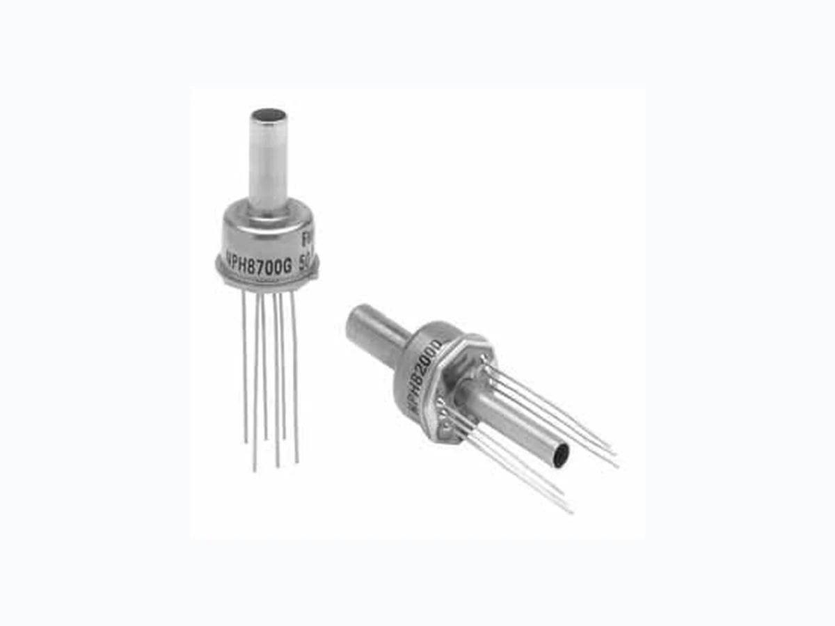
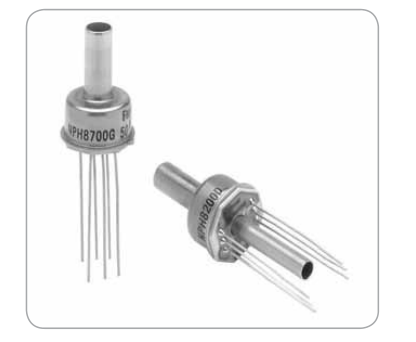
An integrated circuit silicon sensor chip is housed in a standard TO-8 electrical package that is printed circuit board mountable.
The latest techniques in micromachining have been used to ion-implant piezoresistive strain gauges into a wheatstone bridge configuration that is integrally formed on a micromachined silicon diaphragm.
As with all NovaSensor silicon sensors, the NPH Series employs SenStable® processing technology, providing excellent output stability. Constant current excitation to the sensor produces a voltage
output that is linearly proportional to the input pressure.
The user can provide standard signal conditioning circuitry to amplify the 100 mV output signal. The sensor is compatible with most non-corrosive gases and dry air.
A laser-trimmed, thick-film resistor network on a hybrid ceramic substrate provides temperature compensation.
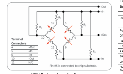
NPH Series schematic diagram
Parameter
Value Units Notes
General
Pressure Range
0 to 10 inH2O (0 to 25 mbar) 0 to 2.5 kPa
0 to 1 psi (0 to 7 bar) 0 to 7 kPa
0 to 5 psi (0 to 0.34 bar) 0 to 30 kPa
Maximum Pressure
5x
rated pressure (10)
Electrical @ 77°F (25°C) Unless Otherwise Stated
Input Excitation
1.5 mA 2 mA maximum
MΩ
Insulation Resistance
100
@ 50 VDC
Ω
Input Impedance
3200
±25%
Ω
Output Impedance
5000
±20%
Ω
Bridge Impedance
5000
±20%
Environmental
Temperature Range
Operating(9)
–40 to 257 °F
(-40°C to 125°C)
Compensated
32 to 158 °F
(0°C to 70°C)
Vibration
10 gRMS 20 to 2000Hz
Shock
100 g 11 milliseconds
cycles
Life (Dynamic Pressure
1 x 10⁶
Cycle)
Mechanical (1)
Weight
<0.2 oz (<5 g)
Media Compatibility
Non-corrosive gases and clean, dry air
Wetted Materials
Top Port
Nickel, gold plated Kovar, silicone gel, gold wire, RTV, silicon and glass.
Bottom Port
Gold plated Kovar, silicon, glass and RTV (9)
Parameter
Min. Typical Max. Min. Typical
Max. Units Notes
2.5
7 & 30
kPa
kPa
Performance Parameters(7), Compensated(1)
Offset
-8 2 8 -4 2 4 mV
Full Scale (FS) Output
2.5 kPa
25 50 90
mV 2
7 kPa
50 75 150 mV 2
30 kPa
75 100 125 mV 2
Linearity
–1.0 0.1
1.0 –0.25 0.05
0.25 %FSO 3
Hysteresis &
-0.2 0.05
0.2 -0.2 0.05
0.2 %FSO
Repeatability
Thermal
Accuracy of
-3 0.5 3 -2 0.5 2 %FSO 4
Offset
Accuracy of FSO –3
–1 3 -1.5 -0.5
1.5 %FSO 4
Thermal
–0.75 0.5
0.75 –0.5 0.2
0.5 %FSO 5
Hysteresis
Short-Term
5
5
µV/V 6, 11
Stability of Offset
Short-Term
5
5
µV/V 6, 11
Stability of FSO
- Performance with offset, thermal accuracy of offset, and thermal accuracy of FSO compensation resistors. 2. FSO with 1.5mA input excitation. 3. Best fit straight line. 4. 32°F to 158°F (0°C to 70°C) with reference to 77°F (25°C) 5. 32°F to 158°F (0°C to 70°C), by design 6. Normalized offset/bridge voltage —100 hrs, typical value, not tested in production. 7. All values measured at 77°F (25°C) and at 1.5 mA, unless otherwise noted. 8. Reduced performance outside compensation range. 9. Backside differential tube is nickel or Kovar. 10. Top side pressure. 11. Typical specifications are for reference only; absolute values may vary.
Page 3
NPH Series Specifications
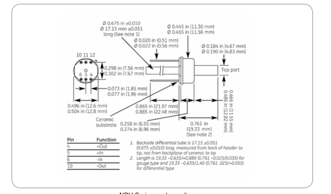
NPH Series package diagram
Ordering Information
The code number to be ordered may be specified as follows: NPH
Code
Package Configuration
8
TO-8
Pressure Range (kPa)
Code
2.5 kPa; 10 inH2O
002.5 007
7 kPa; 1 psi
030
30 kPa; 4.35 psi Code
Pressure
A
Absolute (30 kPa only)
G
Gauge
D
Differential Code
Compensation
H
Hybrid substrate
NPH - _____ - _____ - _____ - _____ Typical model number
Page 4
Amphenol
www.amphenol-sensors.com
© 2014 Amphenol Corporation. All Rights Reserved. Specifications are subject to change without notice.
Advanced Sensors
Other company names and product names used in this document are the registered trademarks or
trademarks of their respective owners.