
DATASHEET SEARCH SITE
Document overview
- Manufacturer or author: Provided By www.digicamel.com(FREE DATASHEET DOWNLOAD SITE)
- PDF pages: 8
Technical content
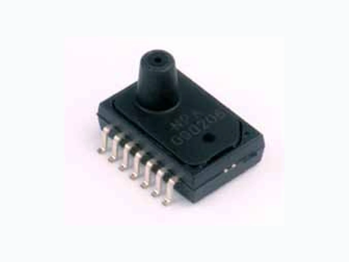
Features
- Surface Mountable
- Differential, Gauge, Absolute & Low Pressure
- 10” H2O to 30 PSI Full Scale
- Output Options: Amplified Analog, Digital Serial (14bit), Digital I2C, Uncalibrated mV
- On chip temperature sensor in digital mode
- Operating temperature range of -40 to 125°C
- Total Error Band < ±1.5% FSO
- 60 psi proof pressure on all ranges Surface-Mount Pressure Sensor Series GE Measurement & Control Solutions GE imagination at work
General NPA Specifications Parameter Value Units Notes Environmental Temperature Range Operating -40 to +125 °C -40 to +257°F Compensated 0 to 60 °C +32 to +157°F Storage -40 to +125 °C -40 to +257°F Mechanical Weight ~1 grams Media Compatibility Positive differential and gauge ports Compatible with exposed materials 1 Negative differential ports Dry gases only Notes: 1. Exposed materials are thermoset plastic, silicon, epoxy, RTV, pyrex and silicone Parameter Units Min Typ Max Notes Common Parameters Accuracy (Total Error Band) %FSO -1.5 1.5 Proof Pressure (10”H2O to 1 psi) psi 35 Proof Pressure (>1 psi to 30 psi) psi 60 Maximum Package Pressure 60 Pressure ranges 10”H2O 30psi Series Excitation Voltage Min/Max Notes NPA-100 1.5mA NPA Uncompensated, mV NPA-300 3.3V 3.135 V to 3.465 V NPA Compensated, low power amplified analog NPA-500 5.0V 4.75 V to 5.25 V NPA Compensated, amplified analog NPA-600 5.0V * 4.75 V to 5.25 V NPA Compensated, digital serial NPA-700 5.0V * 4.75 V to 5.25 V NPA Compensated, digital I2C * 3.3V optional, contact factory for more details
Parameter Units Min Typ Max Analog Performance Parameters 5 volt Excitation Offset Volts 0.44 0.5 0.56 Span Volts 4 Analog Performance Parameters 3.3 volt Excitation Offset Volts 0.46 0.5 0.54 Span Volts 2.5 Typical Analog Circuits Circuit layout same as “Ratiometric Voltage Output” Ratiometric Voltage Output - Standard NPA Absolute Voltage Output - Request Required Ratiometric Voltage Output with Over-Voltage Protection - Request Required NP A S e ns or VS S V g at e V D D S I G NP A S e ns or VS S V g at e V D D S I G V s up pl y +2 .7 to +5 .5 V Vo ut G r ou nd 0. 1µ F NP A S e ns or VS S Vg at e VD D S I G NP A S e ns or VS S Vg at e VD D S I G Vs uppl y +5 .5 to +3 0 V Vo ut G ro und 0. 1µ F MM BF 4 392 NP A S e ns or t V s up pl y +5 to +5 .5 V V o ut G r o und 0. 1µ F J 107 V S S Vg at e V D D S I G NP A S e ns or V S S Vg a e V D D S I G Pin Amplified Analog Function Notes 1 -- 2 -- 3 -- 4 -- 5 --
6 VSS Ground Supply
8 SIG Analog Out, Calibration Interface
9 VDD Supply Voltage
Output Option: Amplified Analog
Output Option: Digital Serial (14 bit) Parameter Units Min Typ Max Notes Digital Performance Resolution ADC 14bit 16383 steps Sampling Rate kHz 1 Digital Serial Output Temperature Sensor Accuracy 4°C 8bit Zacwire—Digital Output (NOM) Bridge Readings with Temperature Option Zacwire—Digital Output (NOM) Bridge Readings Digital Output Options Streaming serial output is a 14 bit number proportional to the full scale. Data Byte Bridge High Data Byte Bridge Low Start Bit Parity Bit Data Byte Data Bit (Example: Bit 2 ½ Stop Bit S P Stop S 0 0 5 4 3 2 1 0 PS 7 6 5 4 3 2 1 0 P½ Stop
2 DATA Byte Packet
3 DATA Byte Packet
Digital Bridge Output with Temperature S 0 0 5 4 3 2 1 0 P S 7 6 5 4 3 2 1 0 P½ Stop S 7 6 5 4 3 2 1 0 P½ Stop Data Byte Bridge High Data Byte Bridge Low Data Byte Temperature Pin Amplified Digital Serial Function Notes 1 -- 2 -- 3 -- 4 -- 5 --
8 SIG Digital Out, Calibration Interface
Output Option: Digital I2C Pin Digital I2C Function Notes 1 -- 2 -- 3 -- 4 -- 5 --
7 VDD Supply Voltage
8 SDA Serial Data, Calibration Interface
9 SCL Serial Clock, Calibration Interface
Digital I2C Update Mode Output Options NPA Pinout Parameter Units Min Typ Max Notes Digital Performance Resolution (ADC) bit 14 16383 steps I2C Slave Address 0x28 Sampling Rate kHz 2 I2C Bit Rate kbits/s 100 400 I2C Mode Update Temperature Accuracy (0 to 60°C) °C 2 11 bit
Output Option: Uncalibrated mV NPA Uncalibrated Performance 10 “H20 to 1 psi 5 psi to 30 psi Parameter Units Min Typ Max Notes Min Typ Max Notes Pressure Range psi 0.36 to 1 10”H2O = 0.361psi = 2.49KPa 5 to 30 Excitation mA 1.5 10 VDC Maximum 1.0 10 VDC Maximum Input Impedance Ω 5000±20% 5000 ±20% Output Impedance Ω 5000±20% 5000 ±20% Zero Offset mV ± 75 ±10 Full Scale Output mV 40 to 120 10 °H20 100 to 166 5 psi to 30 psi 75 to 135 1 psi Linearity %FSO ±0.25 BFSL ±0.25 Pressure Hysteresis %FSO ±0.20 ±0.15 Temperature Coefficient of Zero μV/ V / °C ±30 ±20 Temperature Coefficient of Resistance % /°C 0.29 0.38 Temperature Coefficient of Sensitivity %FSO/°C -0.2 -0.19 Thermal Hysteresis of Zero %FSO ±0.15 ±0.2 Position Sensitivity %FSO 0.2 N/A Pin Uncalibrated mV Function Notes 1 -- 2 --
3 VP Sensor Interface Positive Output
4 VSSP Sensor Interface Ground
11 VN Sensor Interface Negative Output
12 VDDP Sensor Interface Positive Excitation
Manifold Design (All measurements given in mm) Barbed Design Recommended tubing size of 3/32” ID, 7/32” OD, 1/16” wall thickness (All measurements given in mm) No Port Design (All measurements given in mm) Suggested PCB Land Pattern
1 Barb Port — Request Required
Package Leadframe Material: Alloy 194, NiPdAu Plated
© 2011 General Electric Company. All Rights Reserved. Specifications are subject to change without notice. GE is a registered trademark of General Electric Company. Other company or product names mentioned in this document may be trademarks or registered trademarks of their respective companies, which are not affiliated with GE. www.ge-mcs.com 920-477D Model NPA Code Description 100 mV Output, Ratiometric Uncalibrated sensor 300 Analog Amplified Output, 3.3Vdc Excitation, Calibrated sensor
500 Analog Amplified Output, 5Vdc Excitation, Calibrated sensor
600 Zacwire —Digital Serial Output, Calibrated Sensor, 2 byte
601 Zacwire —Digital Serial Output, Calibrated Sensor, 3 byte
2C - Digital output, Calibrated Sensor, 2 byte Code Port Type M 1 manifold port for Gauge and Absolute pressure types B 2 barbed ports for Gauge, Absolute and Differential pressure types** N Non ported Code Pressure Range 10W 10”H20 (2.5 KPa) 001 1 PSI (7 KPa) 005 5 PSI (35 KPa) 015 15 PSI (100 KPa) 030 30 PSI (200 KPa) Code Pressure Type G Gauge D Differential A * Absolute NPA - - Note: * Absolute pressure ranges are available in 15 PSIA and 30 PSIA only. ** 1 barbed port available upon request Contact GE for custom pressure ranges. Refer to application guide 910-289 for more information. Product is RoHS:2010 compliant.
Ordering Information
GE warrants its products against defects in material and workmanship for 12 months from the date of shipment. Products not subjected to misuse will be repaired or replaced. GE reserves the right to make changes without further notice to any products herein. GE makes no warranty, representation or guarantee regarding the suitability of its products for any particular application. GE does not assume any liability arising out of the application or use of any product or circuit and specifically disclaims, and all liability, without limitation consequential or incidental damages. The foregoing warranties are exclusive and in lieu of all other warranties, whether written, oral, implied or statutory. No implied statutory warranty or merchantability or fitness for particular purpose shall apply.