
NP500 NELLSEMI
Document overview
- Manufacturer or author: Provided By www.digicamel.com(FREE DATASHEET DOWNLOAD SITE)
- PDF pages: 7
Technical content
RoHS* COMPLIANT
FEATURES
DESCRIPTION
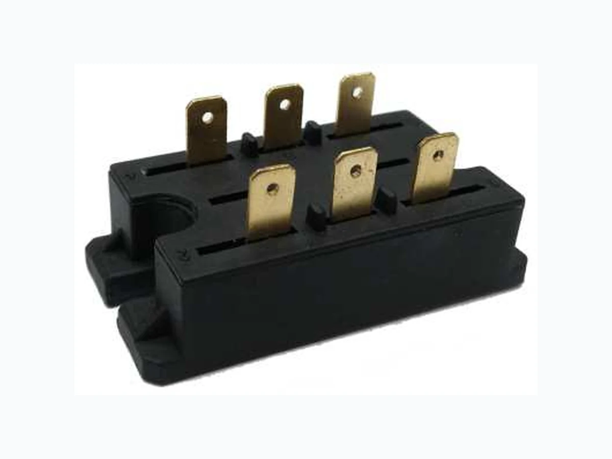
Available up to 1600 V /VRRM DRM Wide choice of circuit configurations The NP500 series of integrated power circuits consists of power thyristors and power diodes configured in a single package . With its isolating base plate , mechanical designs are greatly simplified giving advantages of cost reduction and reduced size . Simplified mechanical design and assembly MAJOR RATINGS AND CHARACTERISTICS A A 2A s 576 1510 1380 SYMBOL lO lTSM , lFSM 2l t Range PRODUCT SUMMARY lO Type Package Circuit 50A Modules - Thyristor ,Standard PACE -PAK (D-19 modified ) Single phase , hybrid bridge common cathode , UNITVALUECHARACTERISTICS www.nellsemi.com Page 1 of 7 Passivated Assembled Circuit Elements, 50A Glass passivated junctions for greater reliability Electrically isolated base plate PACE-PAK (D-19 Modified) High dynamic characteristics UL approved file E320098 Single phase , hybrid bridge doubler connection , Single phase , all SCR bridge VRRM VISOL TJ Tstg 2l √t 80°C 50 Hz 60 Hz 50 Hz 60 Hz 550 15125 400 to 1600 2500 -40 to 125 °C V V 2A √t NP500 Series RoHS RoHS Nell High Power Products Applications include power supplies , control circuits and battery chargers .
V /V , MAXIMUM REPETITIVEDRM RRM PEAK AND OFF-STATE VOLTAGE V V , MAXIMUM NON-REPETITIVERSM PEAK REVERSE VOLTAGE V l MAXIMUMRRM AT T MAXIMUMJ mA NP501 /NP501W /NP501S 400 800 1000 10 1200 1600 RoHS RoHS Nell High Power Products NP502 /NP502W /NP502S NP503 /NP503W /NP503S NP504 /NP504W /NP504S NP505 /NP505W /NP505S 500 900 1100 1300 1700 ON-STATE CONDUCTION PARAMETER SYMBOL UNITTEST CONDITIONS Maximum DC output current at case temperature IO Full bridge circuits A 80 ºC Maximum peak, one cycle non-reptitive on-state or forward current ITSM , IFSM t = 10ms t = 8.3 ms t = 10ms t = 8.3 ms t = 10ms t = 8.3 ms t = 10ms t = 8.3 ms 550 576 460 484 1510 1380 1058 2kA s A 972 ²Maximum l t for fusing 15125 V VTM VT(TO)1 rt1 mΩ 2I √t 2kA √s²Maximum l √t for fusing No voltage reapplied 100%V RRM reapplied No voltage reapplied 100%V RRM reapplied Sinusoidal half wave, initial T = T maximum J J dl/dtMaximum non -repetitive rate of rise of turned -on current Maximum forward voltage drop Maximum on-state voltage drop Low level value of on-state slope resistance Low level value of threshold voltage (16.7 % xɦx l <I<ɦx l ), T = T maximumT(AV) T(AV) J J! (16.7 % xɦy l <I<ɦx l ), T = T maximumT(AV) T (AV) J J! (I>ɦx l ), T = T maximumT(AV) J J! I =150A FM 1.03 9.61 7.01 A/µs 2I t 1.4 1.4 VALUE 0.83 2 2 .l t for time tx = l √t √t x High level value of threshold voltage VT(TO)2 (I>ɦx l ), T = T maximumT(AV) J J! rt2 lL lH Maximum latching current Maximum holding current T = 25°C anode supply = 6V, resistive load J mA 200 130 High level value of on-state slope resistance VFM 250 t = 0.1 to 10 ms, no voltage reapplied T = 125 °C from 0.67 VJ DRM l = 150A, lg = 500 mA, t < 0.5 µs, tp > 6µsTM r I =150A TM T = 25 °CJ T = 25 °CJ V V NP500 Series www.nellsemi.com Page 2 of 7
PARAMETER SYMBOL UNITTEST CONDITIONS VALUES Maximum critical rate of rise of off-state voltage dV/dt T = 125 °C, exponential to 0.67 V , gate openJ DRM V/µs 200 mAlRRM,Maximum peak reverse and off-state leakage current at V , VRRM DRM lDRM, T = 125 °C, gate open circuit J Maximum peak reverse leakage current RMS isolation voltage lRRM lISOL T = 25°CJ
50 Hz, circuit to base , all terminals shorted ,
T = 25 °C, t = 1sJ 2500 µA V TRIGGERING PARAMETER SYMBOL UNITTEST CONDITIONS VALUES PGM VGT 0.2 mA IGM A Maximum peak gate power Maximum average gate power Maximum peak positive gate current Maximum peak negative gate voltage Maximum gate voltage required to trigger Maximum gate current required to trigger Maximum gate voltage that will not trigger Maximum gate current that will not trigger PG(AV) -VGM lGT VGD lGD 2 T = -40°CJ T = 25°CJ T = 125°CJ T = -40°CJ T = 25°CJ T = 125°CJ T = 125°C, rated V appliedJ DRM Anode supply = 6V resistive load V mA V W THERMAL AND MECHANICAL SPECIFICATIONS PARAMETER SYMBOL UNITTEST CONDITIONS VALUES ºC-40 to 125 1.00 0.10 2.0 PACK -PAK (D-19 modified ) g oz. Nm K/W Maximum junction operating and storage temperature range Maximum thermal resistance , junction to case per junction Maximum thermal resistance, case to heatsink (1)Mounting torque , base to heatsink Approximate weight Case style T , TJ stg RthJC RthCS DC operation Mounting surface , smooth and greased RoHS RoHS Nell High Power Products NP500 Series www.nellsemi.com Page 3 of 7 V Note (1) A mounting compound is recommended and the torque should be checked after a period of 3 hours to allow for the spread of the compound
SCHEMATIC DIAGRAM TERMINAL POSITIONS Single phase , hybrid bridge common cathode Blank W Ssingle phase , all SCR bridge Single phase , hybrid bridge common cathode with a freewheeling diode AC1 AC2 (-) (+) AC1 AC2 (-) (+) AC1 AC2 AC1 AC2 G3 G1 AC1 AC2 G4 G2 (-) (+) AC1 AC2 (1)CODING CIRCUIT DESCRIPTION CIRCUIT CONFIGURATION CODE BASIC SERIES Single phase , hybrid bridge common cathode Single phase , hybrid bridge common cathode with a freewheeling diode single phase , all SCR bridge Blank W S NP50X NP50XW NP50XS Note (1) To complete code refer to voltage Ratings table , i.e.: For 1600V of NP50XW , complete code is NP505W . N P Ordering Information Table Device code 50 5 Nell Power semiconductors product Module type Current rating, 50 = 50A DC Circuit configuration W Blank = Single Phase , Hybrid Bridge Common Cathode W = Single Phase , Hybrid Bridge Common Cathode with a freewheeling diode S = Single Phase , all SCR Bridge -4 Voltage code 1 = 400V 2 = 800V 3 = 1000V 4 = 1200V 5 = 1600V NP500 Series www.nellsemi.com Page 4 of 7
Fig.1 Total Power Loss Total output current (A) Maximum total power loss (W) 150 125 100 0 5 10 15 20 25 30 35 40 45 50 180 ° (sine ) T = 125 °CJ Fig.2 On-state power loss characteristics 0 0 10 20 30 40 Maximum total average on-state power loss (W) Average on-state current (A) NP500 Series 180° 120° 90° 60° 30° RMS limit Conduction angle T =125°CJ per junction Fig.3 On-state power loss characteristics Maximum total average on-state power loss (W) Average on-state current (A) 0 10 20 30 50 DC 180° 120° 90° 60° 30° RMS limit Conduction period T =125°CJ per junction Fig.4 Current ratings characteristics 130 120 110 100 70 0 5 10 15 20 25 30 35 40 45 50 Fully turned -on 180 ° (Rect .) 180 ° (Sine ) Per module Maximum allowable case temperature (°C) Total output current (A) Fig.5 On-state voltage drop characteristics Fig.6 Maximum non-repetitive surge current lnstantaneous on-state current (A) 1000 100 lnstantaneous on-state voltage (V) T =25°CJ T =125°CJ Per junction Peak half sine wave on-state current (A) 550 500 450 400 350 300 250 200 150 1 10 100 Number of equal amplitude half cycle current pulses (N) Per junction At Any Rated Load Condition And With Rated V Applied Following SurgeRRM @ 60Hz 0.0083 s @ 50Hz 0.0100 s initial T = 125°CJ www.nellsemi.com Page 5 of 7
Fig.7 Maximum non-repetitive surge current Peak half sine wave on-state current (A) Pulse train duration(s) Maximum Non Repetitive Surge Current Versus Pulse Train Duration. Control Of Conduction May Not Be Maintained Initial T = 125°C, @50HzJ No Voltage Reapplied Rated V ReappliedRRM 600 0.1 10.01 500 400 300 200 100 Per junction Fig.8 Thermal lmpedance Z characteristics thJC Z - transientthJC lmpedance (K/W) 0.1 0.01 0.0001 0.001 0.01 0 .1 1 Square wave pulse duration (s) Steady state value R = 1.00 K/WthJC (DC operation ) Per junction Fig.9 Gate characteristics lnstantaneous gate voltage (V) lnstantaneous gate current (A) 100 0.1 Rectangular gate pulse a) Recommended load line for b) Recommended load line for rated di/dt : 10V, 20 Ω,t <=1µsr rated di/dt : 10V, 65 Ω, t <=1µs r (1) P = 10W, tp = 5msGM (2) P = 20W, tp = 25msGM (3) P = 50W, tp = 1msGM (4) P = 100W, tp = 1msGM VGD IGD T = -40°CJT = 125° C J T = 25°CJ (b) (a) (2) (3) Frequency Limited by P G(AV) (4)(1) 0.001 0.01 0 .1 1 10 100 www.nellsemi.com Page 6 of 7
D-19 PACK-PAK (Modified) NP500 Series RoHS RoHS Nell High Power Products All dimensions in millimeters www.nellsemi.com Page 7 of 7