
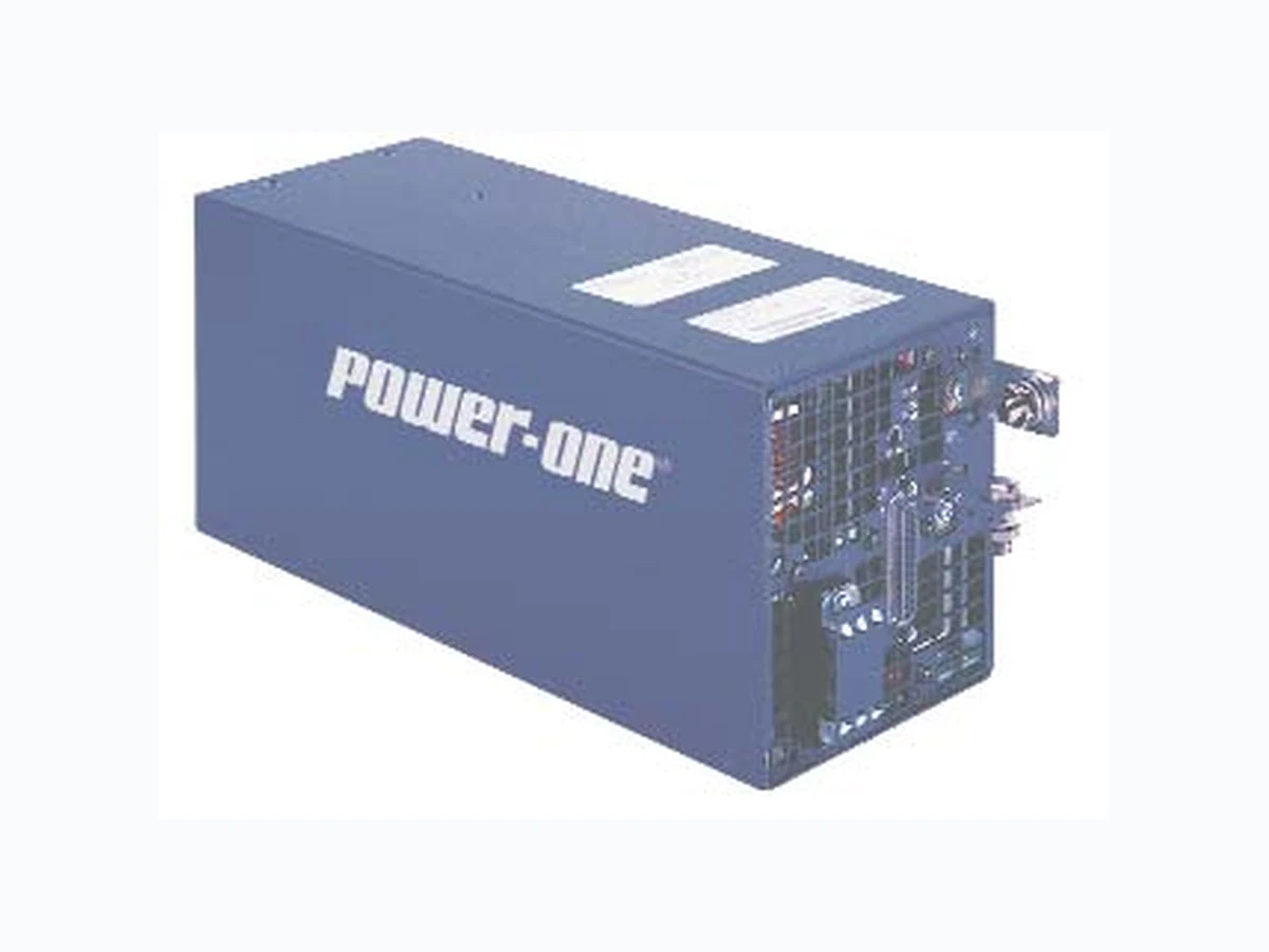
NHC3000 POWER-ONE
Document overview
- Manufacturer or author: Provided By www.digicamel.com(FREE DATASHEET DOWNLOAD SITE)
- PDF pages: 4
Technical content
Features
- Single-phase AC input
- 3U height
- Active current share
- Power Factor Correction (PFC) Meets EN61000-3-2
- Remote voltage adjust, and current monitoring
- Overtemperature, overload, and overvoltage protection
- Power supply status indicators
- Output current meter (bar graph)
- MTBF> 700,000 hours NHC3000 AC-DC Series Data Sheet JUN 03, 2004 revised to MAY 26, 2006 Page 1 of 4 www.power-one.com The NHC3000 Series of chassis-mounted power systems provides AC front-end capability to telecom, data communications and other distributed power designs. The NHC3000 can also be used for many other applications requiring bulk power. NHC3000 power supplies provide excellent protection against input voltage transients. A connector at the rear of the supply provides access to interfaces for remote sensing, remote voltage adjust, current sharing, power supply status, standby logic voltage, remote on/off, and power connections. Airflow for the NHC3000 is from the front through the rear. The output is floating with respect to the chassis and may be used as a positive or negative polarity supply.
Description
MODEL OUTPUT ADJUSTMENT MAXIMUM OUTPUT LINE LOAD RIPPLE & NOISE INITIAL SETTING VOLTAGE RANGE CURRENT REGULATION REGULATION (NOTE 1) %p-p (NOTE 2) ACCURACY NOTES: 1) With Remote Sense connected. 2) Maximum peak-to-peak noise expressed as a percentage of output voltage, 20 MHz bandwidth. Input Specifications PARAMETER CONDITIONS/DESCRIPTION MIN NOM MAX UNITS Input Voltage - AC Single-phase continuous input range. 180 264 VAC Input Frequency AC input. 47 63 Hz Hold-up Time AC turn-off to output greater than or equal to 95%. 16 ms Input Current At full rated load per module. at 230 VAC 15.0 A RMS Inrush Surge Current 30 A PK Power Factor Per EN61000-3-2 at full load. 0.99 W/VAAt half load. 0.98 Operating Frequency Switching frequency 140 kHz
PARAMETER CONDITIONS/DESCRIPTION MIN NOM MAX UNITS Efficiency Full rated load. 88 % Minimum Loads Minimum loading required to maintain regulation. 0 A Output Power Per module. 3000 Watts Overshoot / Undershoot Output voltage overshoot/undershoot at turn-on. ±3.0 % Transient Response Maximum recovery time, to within 1% of initial set point due to a 500 µs 50-100-50% load change, 1A/µs, ±3.0% max. deviation. Turn-On Delay Time AC turn-on to output >95%. 1.2 2.0 Sec Turn-on Rise Time Time required for output voltage to rise from 10% to 90%. 100 ms Interface Signals and Internal Protection PARAMETER CONDITIONS/DESCRIPTION MIN NOM MAX UNITS Overvoltage Protection Latch style overvoltage protection. 24V model 26.4 27.6 28V model 30.8 33.8 V 48V model 52.8 55.2 Overcurrent Protection Constant current limit, as a percentage of maximum rated load. 100 105 110 % Short Circuit Protection Short circuit current, as a percentage of maximum rated load. 110 % Output recovers automatically after removal of short. Overtemperature Module shuts down when internal temperature reaches an unsafe level. DC OK, Output Good (Module) Output low threshold measured at output studs. Form C contacts, ±2 ±5 ±8 % rating is 500 mA at 30 VDC. Input Power Fail Warning Relay closes >5 ms before output drops to <95%. Relay opens after 5 ms output is in regulation. Form C contacts, pull-up to +5 V through a 1 k/H9024resistor. Current Monitor Signal provides an output of 0-10V which applies over 10-100% of rated load. At 50% load: 4.5 5.5 VDC Current Share Accuracy Applies over 10-100% load as a percentage of full load. ±5 % Remote Sense Total voltage compensation for cable losses with respect to the main output. 0.5 V Auxiliary Power (Logic Power) Referenced to negative output terminal and derived from the internal 5.1 VDC. 50 mA Output Margin Margin High - Connect Margin input to Margin Ref. +5 %Margin Low - Connect Margin input to Logic Common. -5 Power Fail Signal PF drops to “0” before output drops to 95% due to loss of AC. & PF Warning Time PF goes to “1” (logic high) after +5 V is in regulation. Form C Warning Time: 5 ms contacts pull up to +5 V through a 1 k /H9024resistor. Output Voltage and Optional - Consult factory for details.. Current Programming Mechanical Specifications PARAMETER CONDITIONS/DESCRIPTION MIN NOM MAX UNITS Input Connector Terminal block. Output Connector Copper bus bar blade with single round hole for 5/16 screw. Signal Connector J1 Power-One P/N 10X0172-001, Amp 247846-4, ITT Common ZEDBL25SBA Mates with Power=One P/N 10X0105-000, Amp 202208-1, ITT Common DBA25-K87-F0 Mating Pin P/N 12X0005-000, Amp 66506-8 Visual Indicators AC-OK LED and DC-OK LED located on the connector end of the supply. Cooling Internal fan; approximately 100 CFM. Mounting See outline drawing. NHC3000 AC-DC Series Data Sheet JUN 03, 2004 revised to MAY 26, 2006 Page 2 of 4 www.power-one.com
Safety, Regulatory, and EMI Specifications PARAMETER CONDITIONS/DESCRIPTION MIN NOM MAX UNITS Agency Approvals UL 60950-1 (UL), CSA C22.2 No. 60950-1, EN60950-1 (TÜV), CE Mark, and CB Report Electromagnetic Interference FCC CFR title 47 Part 15 Sub-Part B. A Conducted & Radiated EN55022 / CISPR 22. A Class ESD Susceptibility Per EN61000-4-2, level 3, direct discharge. 8 kVPer EN61000-4-2, level 3, air discharge. 15 Radiated Susceptibility Per EN61000-4-3, level 3. 10 V/m EFT/Burst Per EN61000-4-4, level 3, @ 5 kHz. 2 kV Input Transient Protection Per EN61000-4-5, level 3. Line to Line 2 kV Conducted Susceptibility Per EN61000-4-6, level 3; 10V from 150 Hz to 80 MHz. Leakage Current Per EN60950. at 240 VAC 1.5 mA Environmental Specifications PARAMETER CONDITIONS/DESCRIPTION MIN NOM MAX UNITS Storage Temperature -40 85 °C Operating Temperature Derate linearly to 60% at 70 °C 0 50 °C Temperature Coefficient After 15-minute warmup. 0.008 %/°C Humidity, Non-Condensing 59 5 % Altitude Derate at 7°C/1000 ft above 8000 ft. 13,000 ft Shock Operating: half-sine 10 ms, 3 axis. +20 GPK Non-operating: half-sine 10 ms, 3 axis. +40 Vibration Operating: swept sine 5-2000-5 Hz, 5-32 Hz, 0.02îDA, 32-2000 Hz. 1 G PK Non-operating: random 10-2000 Hz. 6.15 Grms Acoustics Sound pressure level at 1 meter. 57 dbA Weight 12.1 lb 5.49 kg NHC3000 AC-DC Series Data Sheet JUN 03, 2004 revised to MAY 26, 2006 Page 3 of 4 www.power-one.com NUCLEAR AND MEDICAL APPLICATIONS - Power-One products are not designed, intended for use in, or authorized for use as critical components in life support systems, equipment used in hazardous environments, or nuclear control systems without the express written consent of the respective divisional president of Power-One, Inc. TECHNICAL REVISIONS - The appearance of products, including safety agency certifications pictured on labels, may change dependin g on the date manufactured. Specifications are subject to change without notice.
G HK M N R S T U V W P C 0.25" AIRFLOW DIRECTION N L Callout Inches Millimeters A 12.25 311.2 B 1.50 38.1 C 0.12 3.1 D 5.00 127.0 E 5.00 F 3.98 101.1 G 2.86 72.6 H 0.49 12.5 K 1.17 29.7 M 2.19 55.6 N 1.36 34.5 P 2.16 54.9 R Ø 0.34 Ø 8.6 S 0.80 20.3 T 0.650 16.51 U 3.700 93.98 V 0.825 21.0 W 9.425 239.4 127.0 Pin Description Pin Description
1 DC OK N/C 13 CURRENT SHARE
2 DC OK COM 14 +5V LOGIC
3 DC OK N/O 15 (-) SENSE
4 POWER FAIL PULL UP 16 (+) SENSE
5 ENABLE PULL UP 17 N/U
6 POWER FAIL 18 N/U
7 POWER FAIL RTN 19 I PROGRAM (OPTIONAL
8 REMOTE ON/OFF 20 LOGIC COM
9 REMOTE ON/OFF RTN 21 N/U
10 CURRENT MONITOR 22 N/U
11 MARGIN REF 23 N/U
12 MARGIN 24 N/U
25 RESERVED FOR OPTIONS
NHC3000 AC-DC Series Data Sheet JUN 03, 2004 revised to MAY 26, 2006 Page 4 of 4 www.power-one.com J1 Connector Pinout