
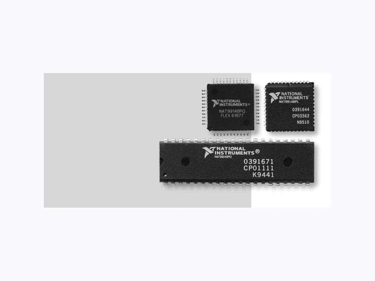
NAT9914BPL ETC1
Document overview
- Manufacturer or author: Provided By www.digicamel.com(FREE DATASHEET DOWNLOAD SITE)
- PDF pages: 10
Technical content
IEEE 488.2 Controller Chip
Description
The NAT9914 IEEE 488.2 controller chip can perform all the interface functions defined by the IEEE Standard 488.1-1987,and also meets the additional requirements and recommendations of the IEEE Standard 488.2-1987. Connected between the processor and the IEEE 488 bus, the NAT9914 provides high- level management of the IEEE 488 bus, significantly increases the throughput of driver software, and simplifies both the hardware and software design. The NAT9914 performs complete IEEE 488 Talker, Listener, and Controller functions. In addition to its numerous improvements, the NAT9914 is also completely pin compatible with the TI TMS 9914A and software compatible with the NEC µPD7210 and TI TMS9914A controller chips. IEEE 488.2 Overview The IEEE 488.2 standard removes the ambiguities of IEEE 488.1 by standardizing the way instruments and controllers operate. It defines data formats, status reporting, error handling, and common configuration commands to which all IEEE 488.2 instruments must respond in a precise manner. It also defines a set of controller requirements. With IEEE 488.2, you gain the benefits of reduced development time and cost because systems are more compatible and reliable. The NAT9914 brings the full power of IEEE 488.2 to the design engineer along with numerous other design and performance benefits, while retaining the 40-pin and 44-pin hardware configurations of the TI TMS 9914A. General The NAT9914 manages the IEEE 488 bus. You program the IEEE 488 bus by writing control words into the appropriate registers. CPU-readable status registers supply operational feedback. The NAT9914 mode determines the function of these registers. On power up or reset, the NAT9914 registers resemble those of the TMS9914A set, with additional registers that supply extra functionality and IEEE 488.2 compatibility. In this mode, the NAT9914 is completely pin compatible with the TI TMS9914A. If you enable the 7210 mode, the registers resemble those of the NEC µPD7210 set, with additional registers that supply extra functionality and IEEE 488.2 compatibility. This mode is not pin compatible with the NECµPD7210. Figure 4 shows the key components of the NAT9914. NAT9914 Pin compatible with TI TMS9914A Software compatible with NEC µPD7210 or TI TMS9914A controller chips Low power consumption Meets all IEEE 488.2 requirements Bus line monitoring Preferred implementation of requesting service Will not send messages when there are no Listeners Performs all IEEE 488.1 interface functions Programmable data transfer rate (T1 delays of 350 ns, 500 ns, 1.1 µs, and 2 µs) Automatic EOS and/or NL message detection Direct memory access (DMA) Automatically processes IEEE 488 commands and reads undefined commands TTL-compatible CMOS device Programmable clock rate
20 MHz maximum
ni.com/store
Trigger asserts when one of the trigger conditions is satisfied. Controller asserts when the NAT9914 is Controller-In-Charge. The pin contains an internal pull-up resistor of 25 kΩ to 100 kΩ . In controller applications where the CLK signal frequency is > 8 MHz, IFC* should be pulled up with a 4.7 kΩ resistor. RS0 and RS1 contain an internal pull-up resistor of 25 kΩ to 100 kΩ . RS2 does not contain an internal pull-up or pull-down resistor. Figure 4. NAT9914 Block Diagram
IEEE 488.2 Controller Chip National Instruments Tel: (512) 794-0100 • Fax: (512) 683-9300 • info@ni.com • ni.com/gpib
9914 Mode Registers
In 9914 mode, the NAT9914 registers consist of all the TI TMS9914A registers and two types of additional registers – newly defined registers and paged-in registers. The NAT9914 maps the newly defined registers into the unused portion of the 9914 address space. Each paged-in register appears at Offset 2 immediately after you issue an auxiliary page-in command, and it remains there until you page another register into the same space or you issue a reset. The table below lists all the registers in the 9914 register set. See the NAT9914 Reference Manual available at ni.com for more information.
7210 Mode Registers
The NAT9914 registers include all the NEC µPD7210 registers plus two types of additional registers – extra auxiliary registers and paged-in registers. You write the extra auxiliary registers the same as standard µPD7210 auxiliary registers. On issuing an auxiliary page-in command, the paged-in registers appear at the same offsets as existing µPD7210 registers. At the end of the next CPU access, the chip pages out the paged-in registers. The following table lists all the registers in the 7210 mode register set. See the NAT9914 Reference Manual available at ni.com for more information. Register PAGE-IN RS(2-0) WE* DBIN CE* ACCGR* Interrupt Status 0 U 0 0 0 1 1 0 1 Interrupt Mask 0 U 0 0 0 0 0 0 1 Interrupt Status 1 U 0 0 1 1 1 0 1 Interrupt Mask 1 U 0 0 1 0 0 0 1 Address Status U 0 1 0 1 1 0 1 Interrupt Mask 2 P 0 1 0 0 0 0 1 End-of-String P 0 1 0 0 0 0 1 Bus Control P 0 1 0 0 0 0 1 Accessory P 0 1 0 0 0 0 1 Bus Status U 0 1 1 1 1 0 1 Auxiliary Command U 0 1 1 0 0 0 1 Interrupt Status 2 P 1 0 0 1 1 0 1 Address U 1 0 0 0 0 0 1 Serial Poll Status P 1 0 1 1 1 0 1 Serial Poll Mode U 1 0 1 0 0 0 1 Command Pass Through U 1 1 0 1 1 0 1 Parallel Poll U 1 1 0 0 0 0 1 Data-In U 1 1 1 1 1 0 1 Data-In U X X X X 0 X 0 Command/Data Out U 1 1 1 0 0 0 1 Command/Data Out U X X X 0 1 X 0 The ' ' symbol denotes features (such as registers and auxiliary commands) that are not available in the TMS9914A. Notes for the PAGE-IN column: U = Page-in auxiliary commands do not affect the register offset. P = The register offset is valid only after a page-in auxiliary command. Register PAGE-IN A(2-0) WE* DBIN CE* ACCGR* Data-In U 0 0 0 1 1 0 1 Data-In X X X X X 0 X 0 Command/Data Out U 0 0 0 0 0 0 1 Command/Data Out X X X X 0 1 X 0 Interrupt Status 1 U 0 0 1 1 1 0 1 Interrupt Mask 1 U 0 0 1 0 0 0 1 Interrupt Status 2 U 0 1 0 1 1 0 1 Interrupt Mask 2 U 0 1 0 0 0 0 1 Serial Poll Status N 0 1 1 1 1 0 1 Serial Poll Mode N 0 1 1 0 0 0 1 Version P 0 1 1 1 1 0 1 Internal Counter 2 P 0 1 1 0 0 0 1 Address Status U 1 0 0 1 1 0 1 Address Mode U 1 0 0 0 0 0 1 Command Pass Through N 1 0 1 1 1 0 1 Auxiliary Mode U 1 0 1 0 0 0 1 Source/Acceptor Status P1 0 1 11 01 Address 0 N 1 1 0 1 1 0 1 Address N 1 1 0 0 0 0 1 Interrupt Status 0 P1 1 0 11 01 Interrupt Mask 0 P1 1 0 00 01 Address 1 N 1 1 1 1 1 0 1 End-of-String N 1 1 1 0 0 0 1 Bus Status P1 1 1 11 01 Bus Control P1 1 1 00 01 The ' ' symbol denotes features (such as registers and auxiliary commands) that are not available in the NEC7210. Notes for the PAGE-IN column: U = The page-in auxiliary command does not affect the register. N = The register offset is always valid except for immediately after a page-in auxiliary command. P = The register is valid only immediately after a page-in auxiliary command.
9914 Register Set 7210 Register Set
Figure 13. Typical CPU Systems with NAT9914
Figure 16. Mechanical 44-pin QFP .
IEEE 488.2 Controller Chip Technical Support National Instruments strives to provide you with quality technical assistance worldwide. We currently offer electronic technical support along with our technical support centers staffed by applications engineers. Access information from our Web site at ni.com Our FTP site is dedicated to 24-hour support, with a collection of files and documents to answer your questions. Log on to our Internet host at ftp.ni.com You can fax questions to our applications engineers anytime at (800) 328-2203 or (512) 683-5678. Or, you can call from Internationally, contact your local office. National Instruments sponsors a wide variety of group activities, such as user group meetings at trade shows and at large industrial sites. Our users also receive our quarterly newsletters Instrumentation Newsletter and AutomationView to get the latest information on new products, product updates, application tips, and current events. In addition, sign up for NI News, our electronic news service at ni.com/news Warranty All National Instruments data acquisition, computer-based instrument, VXIbus, and MXI bus products are covered by a one- year warranty. GPIB hardware products are covered by a two-year warranty from the date of shipment. The warranty covers board failures, components, cables, connectors, and switches, but does not cover faults caused by misuse. The owner may return a failed assembly to National Instruments for repair during the warranty period. Extended warranties are available at an additional charge. Information furnished by National Instruments is believed to be accurate and reliable. National Instruments reserves the right to change product specifications without notice. Seminars/Training Free and fee-paid seminars are presented several times a year in cities around the world. Comprehensive, fee-paid training courses are available at National Instruments offices or at customer sites. Call for training schedules. U.S. Corporate Headquarters• Fax: (512) 683-9300 • info@ni.com Branch Offices: Australia03 9879 5166 • Austria 0662 45 79 90 0 • Belgium 02 757 00 20 • Brazil 000817 947 8791 • Canada 514 694 8521 • China 021 6555 7838 Czech Republic420 2 2423 5774 • Denmark 45 76 26 00 • Finland 09 725 725 11 • France 01 48 14 24 24 • Germany 089 741 31 30 • Greece 30 1 42 96 427 Hong Kong2645 3186 • India 91 80 535 5406 • Israel 03 6393737 • Italy 02 413091 • Japan 03 5472 2970 • Korea 02 596 7456 • Malaysia603 9596711 Mexico 001 800 010 0793 • Netherlands0348 433466 • New Zealand09 914 0488 • Norway 32 27 73 00 • Poland 48 22 528 94 06 • Portugal351 210 311 210 Russia 095 238 7139 • Singapore2265886 • Slovenia386 3 425 4200 • South Africa082 877 8530 • Spain 91 640 0085 • Sweden 08 587 895 00 Switzerland056 200 51 51 • Taiwan02 2528 7227 • U.K. 01635 523545 • Venezuela800 1 4466 © Copyright 2001 National Instruments Corporation. All rights reserved. Product and company names listed are trademarks or trade names of their respective companies. 041001 ni.com/gpi (512) 794-0100 *340497D-01* 340497D-01
Ordering Information
a. Family name – NAT = 8-bit GPIB Talker/Listener/Controller interface b. Device number – 9914 = TI TMS9914A pin-compatible part c. Revision d. Package material – P = plastic e. Package type – D = Dual Inline Package (DIP) L = Plastic Leaded Chip Carrier (PLCC) Q = Quad Flatpack (QFP)