
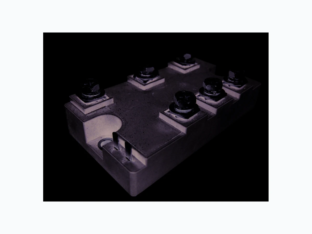
MTPT100 NELLSEMI
Document overview
- Manufacturer or author: Provided By www.digicamel.com(FREE DATASHEET DOWNLOAD SITE)
- PDF pages: 5
Technical content
FEATURES
UL recognition file number E320098 Small volume, light weight Three-phase bridge and a thyristor Epoxy meets UL 94 V-O flammability rating PRIMARY CHARACTERRISTICS IF(AV) Weight: 250g (8.8 ozs) 100A VRRM 800V to 1600V 1.3V 20 µA 150ºC IFSM IR V /FM VTM SEMICONDUCTOR RoHS RoHS Page 1 of 5 Three-Phase Bridge + Thyristor, 100A Nell High Power Products Compliant to RoHS High surge current capability Low thermal resistance Small thermal resistance ADVANTAGE TJ max. 1200A MTPT10008 Thru MTPT10016 Isolation voltage up to 2500V International standard package MTPT100 All dimensions in millimeters
Applications
lnverter for AC or DC motor control Current stablilzed power supply Switching power supply 2- 5.5 6-M5 SCREWS 30 2032 93.5MAX 2020 18 50.5M AX17 22M AX 294 ~ ~ ~ + -R2 KG + -R2G
MAJOR RATINGS AND CHARACTERISTICS (T = 25°C unless otherwise noted)A PARAMETER V V SYMBOL MTPT100 UNIT 900 1300 800 1200 1600 12 16 1700 Maximum repetitive peak reverse voltage Peak reverse non-repetitive voltage Peak forward surge current single sine-wave superimposed on rated load Rating (non-repetitive, for t greater than 1 ms and less than 8.3 ms) for fusing Operating junction temperature range V /RRM VRRM VRSM IFSM 2I t 7200 100 -40 to 150 1200 2A s A A ºC ELECTRICAL CHARACTERISTICS (T = 25°C unless otherwise noted)A PARAMETER V µA SYMBOL MTPT100 UNIT 08 12 16 Maximum instantaneous forward drop per diode Maximum reverse DC current at rated DC blocking VF IR 1.3 voltage per diod TEST CONDITIONS I = 100AF T = 25°CA T = 150°CA Storage temperature range TSTG -40 to 125 ºC TJ mA MTPT100 Maximum Ratings for Diodes Output DC current three-phase full wave, T = 100°Cc IO FORWARD CONDUCTION PARAMETER SYMBOL TEST CONDITIONS Maximum average on -state current at case temperature I T(AV) 180° conduction, half sine wave ,50Hz A Maximum peak, one-cycle, on-state non-repetitive surge current I TSM t = 10 ms No voltage reapplied Sine half wave, initial T J TJ maximum t = 8.3 ms Maximum I t for fusing I A Maximum I t for fusing I t t = 0.1 ms to 10 ms, no voltage reapplied Maximum on-state voltage drop VTM I TM = 100A , T J = 25 °C, 180° conduction Maximum holding current IH Anode supply = 12 V initial I T = 30 A, T J = 25 °C mA Maximum latching current IL Anode supply = 12 V resistive load = 1 Ω Gate pulse: 10 V, 100 μs, T J = 25 °C 400 V UNITSVALUES 100 1200 1260 7200 6570 1.3 100 A t = 10 ms t = 8.3 ms t = 10 ms t = 8.3 ms kA2√s 5040 4590 reapplied 100%VRRM Maximum Ratings fo Thyristor SWITCHING PARAMETER SYMBOL TEST CONDITIONS VALUES Typical delay time Typical rise time td tr TJ = 25 °C ,gate current = 1A dl /dt = 1 A/µsg Typical tum-off time tq I = 300A ; dl/dt = 15 A/µs ; T = T maximum,TM J J V = 50V ; dV/dt = 20V/µs ; gate 0V ,100Ω R μs 50 to 150 UNITS V = 0.67 % Vd DRM
PARAMETER SYMBOL TEST CONDITIONS VALUES UNITS Maximum peak gate power PGM t p 5 ms, T J = T J maximum W Maximum average gate power PG(AV) f = 50 Hz, T J = T J maximum Maximum peak gate current IGM t p 5 ms, T J = T J maximum A Maximum peak negative gate voltage - V GT V gate voltage V GT Anode supply = 12 V, resistive load; R a = 1 TJ = 25 °C I GT mA Maximum gate voltage that will not trigger V GD TJ = T J maximum, 67% V DRM applied 0.25 Maximum gate current that will not trigger I GD mA Maximum rate of rise of turned-on current dI/dt TJ = 25ºC ,I = 1.5A ,t ≤ 0.5 µsGM r A/μs THERMAL AND MECHANICAL SPECIFICATIONS PARAMETER SYMBOL TEST CONDITIONS VALUES UNITS junction operating and storage temperature range TJ, Tstg - 40 to 125 Maximum thermal resistance, junction to case per junction R thJC DC operation Typical thermal resistance, case to heatsink per module R thCS Mounting surface, smooth , flat and greased Mounting torque ± 10 % to heatsink, M5 A mounting compound is recommended and the torque should be rechecked after a period of about 3 hours to allow for the spread of the compound. to terminal, M5 Approximate weight 250 8.8 TRIGGERING J J J = T J J J - V GT Maximum required DC to trigger a Ω Maximum required DC gate current to trigger = T thCS 100 V oz. g 0.12 0.3 BLOCKING PARAMETER SYMBOL TEST CONDITIONS VALUES Maximum peak reverse and off-state leakage current I RRM I DRM TJ = 125 °C RMS isolation Voltage VISO
50 Hz, circuit to base,
all terminals shorted, 25 ºC ,60s V Critical rate of rise of off-state voltage dV/dt TJ = T J maximum, exponential to 67 % rated V DRM V/μs 500 mA 2500 UNITS N.m 150 SEMICONDUCTOR RoHS RoHS MTPT100 Nell High Power Products Device code 100 16MTPT 321 - I rating : "100" for 100 AF(AV) RRM - Voltage code : code x 100 = V Module type : “MTPT” for 3Ø Br dge + Thyr stori i
0 ID 20
W 240 180 120 Pvtot Fig.1 Power dissipation 100A806040 Three phase 0 °C 150 200 A 160 120 I D Fig.2 Forward current derating curve 10050Tc Three phase 0.001 0.20 °C/ W 0.10 Fig.3 Transient thermal impedance 100S101.00.10.01t Zth(j-C) A 2000 1000 Fig.4 Max non-repetitive forward surge current 100 cycles10 50HZ Per one element Single phase half wave T =25j °C start 0.5 V F 1.0 1000 A 100 IF Fig.5 Forward characteristics V 2.01.5 2.5 T =25j °C max. 150 W 120 PTAV 0 ID Fig.6 SCR power dissipation 100A80604020
101 I G
V 0.1 Fig.10 Gate trigger characteristics 102 103 104 VG 100 0 150 200 A 160 120 ITAVM Fig.7 SCR forward current derating curve 10050Tc °C 0.001 0.50 °C / W 0.25 Fig.8 SCR transient thermal impedance 100S101.00.10.01t Zth(j-C) 0.5 V TM 1.0 1000 A 100 IT Fig.9 SCR forward characteristics 2.5 V2.01.5 max. T =25j °C max. Average Gate Power (3W) Peak Gate Power (10W) Peak Forward Gate Voltage (10V) Maximum Gate Non-Trigger Voltage 25°C -10°C 135°C Peak Gate Current (3A) mA