
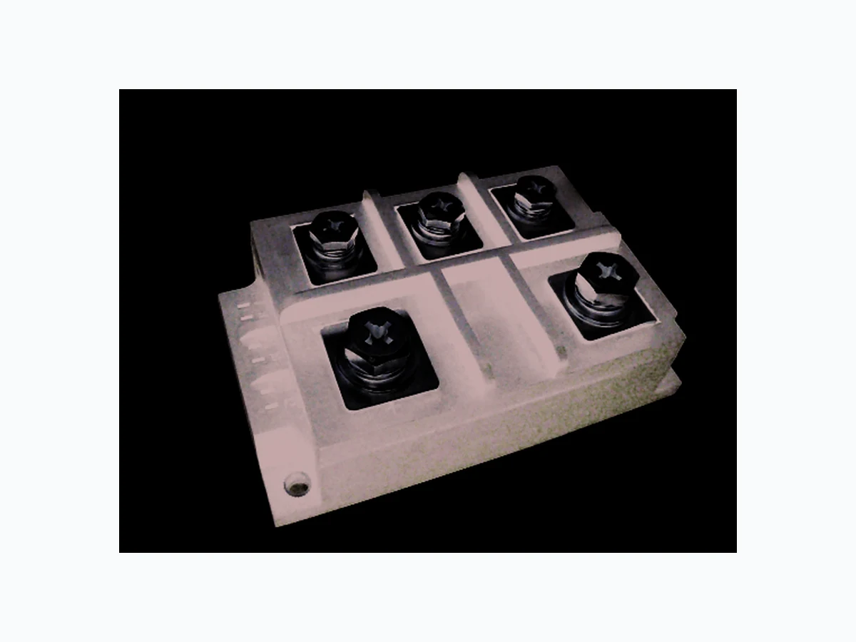
MTP400 NELLSEMI
Document overview
- Manufacturer or author: Provided By www.digicamel.com(FREE DATASHEET DOWNLOAD SITE)
- PDF pages: 3
Technical content
FEATURES
UL recognition file number E320098 Small volume, light weight Typical IR less than 5.0 µA TYPICAL APPLICATIONS Epoxy meets UL 94 V-O flammability rating PRIMARY CHARACTERRISTICS IF(AV) 400A VRRM 800V to 1800V 1.30V 20 µA 150ºC IFSM IR VF SEMICONDUCTOR RoHS RoHS Three-Phase Bridge Rectifier, 400A Nell High Power Products Compliant to RoHS High surge current capability Low thermal resistance Weight: 1100g (38.8 ozs) ADVANTAGE TJ max. 6000A MTP40008 Thru MTP40018 Isolation voltage up to 2500V International standard package All dimensions in millimeters MTP400 Series 68.00 70.00 123.00 142.0 4-ø6.5 Field supplies for DC motors DC power supplies for apparatus device Input rectifying power supplies for PWM converters Inverter welders 66.50 41.50 84.0 ~ ~ ~ 42.0 7.5 2-M10 Screw 3-M8 Screw Page 1 of 3www.nellsemi.com + -
MAJOR RATINGS AND CHARACTERISTICS (T = 25°C unless otherwise noted)A PARAMETER V V SYMBOL MTP400 UNIT 1900 900 1100 1300 1800800 1000 1200 1600 181210 16 1700 1800800 1000 1200 1600 V Maximum repetitive peak reverse voltage Peak reverse non-repetitive voltage Maximum DC blocking voltage Maximum average forward rectified output current at T = 100°C C Peak forward surge current single sine-wave superimposed on rated load Rating (non-repetitive, for t greater than 1 ms and less than 8.3 ms) for fusing RMS isolation voltage from case to leads Operating junction storage temperature range VRRM VRSM IFSM VDC IF(AV) VISO 2I t 2500 149.4 400 -40 to 150 6000 2KA s A A V ºC ELECTRICAL CHARACTERISTICS (T = 25°C unless otherwise noted)A PARAMETER V µA SYMBOL MTP400 UNIT 08 181210 16 Maximum instantaneous forward drop per diode Maximum reverse DC current at rated DC blocking VF IR 1.30 voltage per diod TEST CONDITIONS I = 400AF T = 25°CA T = 150°CA THERMAL AND MECHANICAC (T = 25°C unless otherwise noted)A PARAMETER °C/W SYMBOL MTP400 UNIT 08 181210 16 Typical thermal resistance (1) With heatsink, single side heat dissipation, half sine wave. (1)RθJC 0.065 Notes Storage temperature range TSTG -40 to 125 ºC TJ TEST CONDITIONS junction to case Single-side heat dissipation, sine half wave Mounting ± 10 % to heatsink M6 A mounting compound is recommended and the torque should be rechecked after a for the spread period of 3 hours to allow of the compound. Nmto terminal M8 Approximate weight 1100 torque g - Module type: ”MTP” for 3Ø Brıdge RRM Device code - Voltage code:code x 100 = V I rating:"400" for 400 AF(AV) mA MTP 400 16 Page 2 of 3www.nellsemi.com to terminal M10 MTP400 Series
Fig.1 Forward current vs. Forward voltage Fig.2 Thermal lmpedance (junction to case) Fig.3 Power Consumption vs. Avergage Current Fig.4 Case Temperature vs. O-state Average Current Fig.5 Forward Surge Current vs. Cycle 2Fig.6 I t characteristic Case Temperature (°C) On-state average current (A) Peak on-state current (A) Time (s) Time (ms) Cycle @ 50Hz Forward surge current (A) Peak on-state voltage (V) Transient Thermal Impedance (°C/W) On-state Power consumption (W) On-state average current(A) 2 2I t (KA S) 2.5 2.0 1.5 1.0 0.5 10 100 1000 0.06 0.08 0.04 0.02 0.001 0.01 0.1 1 10 1000 400 800 200 600 0 300100 200 500 400 300 200 100 0 30 60 90 120 150 180 4500 3000 1500 1 10 100 120 1 10 1200 400 500 1400 6000 T =25°CJ Page 3 of 3www.nellsemi.com 150 180 MTP400 Series