


 Download PDF
PSE19 SCHURTER
Document overview
- PDF pages: 7
Technical content
Page 1
Product manual
Snap-in switch
for switches PSE, MSM and MCS 30
CONTENTS
1. PRODUCT DESCRIPTION
2. DATA AND DIMENSIONAL DRAWINGS
2.1. Technical Data 2.2. Dimensions of PSE with a Mounting Diameter 19 mm Dimensions of PSE with a Mounting Diameter 22 mm Dimensions of PSE with a Mounting Diameter 24 mm Dimensions of PSE with a Mounting Diameter 27 mm Dimensions of PSE with a Mounting Diameter 30 mm Dimensions of MSM with a Mounting Diameter 22 mm Dimensions of MSM with a Mounting Diameter 30 mm Dimensions of MCS 30 with a Mounting Diameter 30 mm 2.3. Cut-out 2.4. Assembling Instruction
3. ORDER NUMBERS
3.1. MSM 22 3.2. Variants Parts List
4. PACKAGING
| Änderungen, die dem technischen Fortschritt dienen, bleiben vorbehalten | |||||||
| Seite | Erstelldatum: | Ersteller: | Änderungsdatum: | Geändert von: | Änderungs-Nr. | Datenblatt Nr. | Index |
| 1 of 7 | 29.09.2005 | Birmelin | 17.01.07 | Birmelin | 9353 | 105.9511 | c |
Page 2
1
PRODUCT DESCRIPTION
The advantage of the switches with snap-in mounting is that the switches can be assembled from the front side of the equipment without additional fastening from the rear side. Due to this method of mounting, the metal switches can be used in applications with limited assembly space or where the access to the rear side of the housing is not possible. This means that the switches can adapt where conventional switches will not be applied. Furthermore, this type of mounting realizes cost savings by a significant reduction of assembly time. The assembly becomes effective by the force fitting of the switch into the drilling hole, whereas the O- Ring will be displaced. After inserting the switch through the drilling hole, the O-Ring expands and the
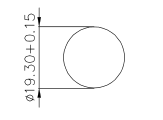
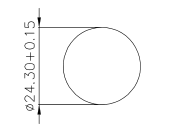
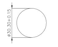
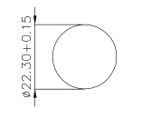
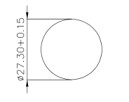
switch is fixed in the drilling hole. It must be pointed out that the panel cut-out is without flash and the set-up of the drilling diameter has to lie in a minimum range of tolerance (+ 0.15 mm to the nominal drilling diameter), so that a protective position of the switch can be guaranteed. Also the thickness of the front panel is important as the position of the switch is determined by the panel thickness. By using sharp objects the switch can be released from the front panel. Therefore, switches with such an assembling technique are only suitable to a minimum extent in applications which are exposed to vandalism.
DATA AND DIMENSIONAL DRAWINGS
2
2.1 Technical Data The technical data for the assembling of the snap-in switches is listed in this section. The mechanical, electrical and climatical features of the used switches are described in their particular product manuals.
| Mounting Diameter [mm] | 19, 22, 24, 27, 30 |
| Standard Front Panel Thickness [mm] | 1.5; 2.0; 2.5; 3.0 |
| Assembly Force [N] | 50 - 100 |
| Drilling Tolerance [mm] | max. + 0.15 Panel cut-out without flash |
| Torsion Protection | without Torsion Protection If the switch is assembled in right direction, lettered switches can be used. |
| ESD-Protection | In combination with a coated or anodised surface of the front panel the ESD protection cannot be guaranteed. |
| Änderungen, die dem technischen Fortschritt dienen, bleiben vorbehalten | |||||||
| Seite | Erstelldatum: | Ersteller: | Änderungsdatum: | Geändert von: | Änderungs-Nr. | Datenblatt Nr. | Index |
| 2 of 7 | 29.09.2005 | Birmelin | 17.01.07 | Birmelin | 9353 | 105.9511 | c |
Page 3
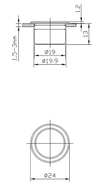
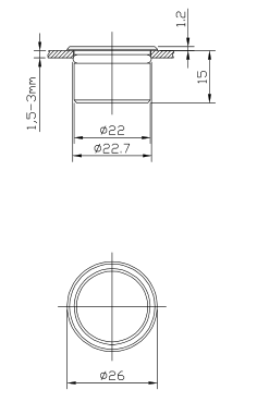
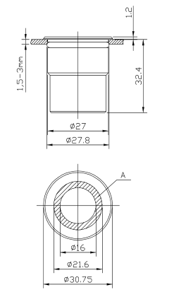
2.2 Dimensional drawings
PSE 19
PSE 22
PSE 24 RI
PSE 27 RI
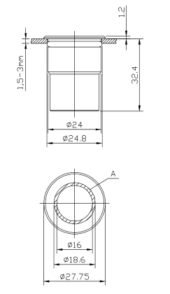
A = Illuminated Surface
A = Illuminated Surface
| Änderungen, die dem technischen Fortschritt dienen, bleiben vorbehalten | |||||||
| Seite | Erstelldatum: | Ersteller: | Änderungsdatum: | Geändert von: | Änderungs-Nr. | Datenblatt Nr. | Index |
| 3 of 7 | 29.09.2005 | Birmelin | 17.01.07 | Birmelin | 9353 | 105.9511 | c |
Page 4
PSE 30 RI
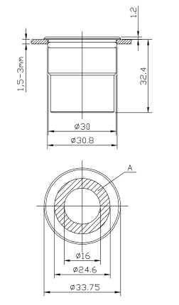
A = Illuminated Surface
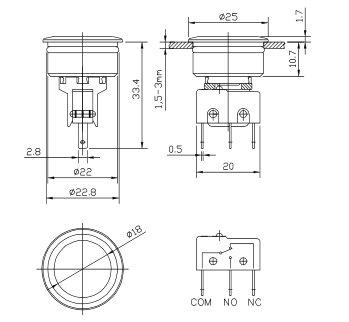
MSM 22
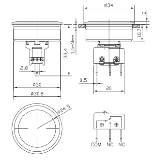
MSM 30
| Änderungen, die dem technischen Fortschritt dienen, bleiben vorbehalten | |||||
| Seite Erste | lldatum: Ersteller: | Änderungsdatum: Geändert v | on: Änderungs-Nr. | Datenblatt Nr. | Index |
| 4 of 7 29.0 | 9.2005 Birmelin | 17.01.07 Birmelin | 9353 | 105.9511 | c |
Page 5
MCS 30
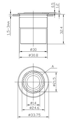
A = Illuminated Surface
| Änderungen, die dem technischen Fortschritt dienen, bleiben vorbehalten | |||||||
| Seite Er | stelldatum: | Ersteller: | Änderungsdatum: | Geändert von: | Änderungs-Nr. | Datenblatt Nr. | Index |
| 5 of 7 29 | .09.2005 | Birmelin | 17.01.07 | Birmelin | 9353 | 105.9511 | c |
Page 6
2.3 Cut-out
Mounting Diameter 19 mm
Mounting Diameter 24 mm
Mounting Diameter 30 mm
2.4 Assembling Instruction
Mounting Diameter 22 mm
Mounting Diameter 27 mm




| Änderungen, die dem technischen Fortschritt dienen, bleiben vorbehalten | |||||||
| Seite Erst | elldatum: | Ersteller: | Änderungsdatum: | Geändert von: | Änderungs-Nr. | Datenblatt Nr. | Index |
| 6 of 7 29.0 | 9.2005 | Birmelin | 17.01.07 | Birmelin | 9353 | 105.9511 | c |
Page 7
3
ORDER NUMBERS
3.1 MSM 22
| Mounting Diameter [mm] Ø 22 Ø 22 | ||
| Front Panel Thickness [mm] | 1.5 | 2.0 |
| Electrical Rating | max. 5A / 125VAC or 3A / 250VAC | |
| Standard | 1241.6695.1120000 | 1241.6699.1120000 |
| Point Illumination - red | 1241.6693.1121000 | 1241.6697.1121000 |
| Point Illumination - green | 1241.6693.1122000 | 1241.6697.1122000 |
3.2 Variants Parts List
Mounting Diameter (mm)
Ø 19
Ø 22
Ø 24
Ø 27
Ø 30
| MSM | X | X | |||
| MSM labelled * | X | X | |||
| MSM Point Illumination * | X | X | |||
| MSM Ring Illumination | X | X | |||
| MCS 30 Ring Illumination | X | ||||
| PSE * | X | X | |||
| PSE Ring Illumination | X | X | X |
\* The switches are provided without torsion protection.
By a correct positioning of the switch while assembling, also lettered and illuminated switches can be used.
For product requesting, please determine the standard article type and furthermore declare for the snap-in version the thickness of the front panel.
4
PACKAGING
The MSM 22 switches are packaged into a carton with a patterned inlay where 10 parts are included. The MSM 30 configuration as well as the MCS 30 and the PSE are packaged into boxes either with inlays or with air cushion bags, dependent on the connection configuration.
| Änderungen, die dem technischen Fortschritt dienen, bleiben vorbehalten | |||||||
| Seite | Erstelldatum: | Ersteller: | Änderungsdatum: | Geändert von: | Änderungs-Nr. | Datenblatt Nr. | Index |
| 7 of 7 | 29.09.2005 | Birmelin | 17.01.07 | Birmelin | 9353 | 105.9511 | c |