


 Download PDF
DATASHEET SEARCH SITE
Document overview
- PDF pages: 5
Technical content
Page 1
MIL-PRF-38534 AND 38535 CERTIFIED FACILITY

4707 Dey Road Liverpool, N.Y. 13088
(315) 701-6751
FEATURES:
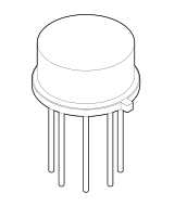
Industry Wide LH0002 Replacement High Input Impedance-180KΩ Min Low Output Impedance-10Ω Max Low Harmonic Distortion DC to 30 MHz Bandwidth Slew Rate is Typically 400 V/μS Operating Range from±5V to ±20V Available to DSCC SMD5962-7801301XC Equivalent Rad Hard Device MSK 0002RH
DESCRIPTION:
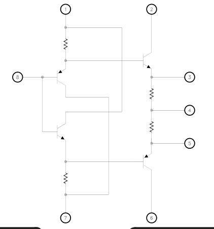
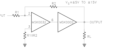
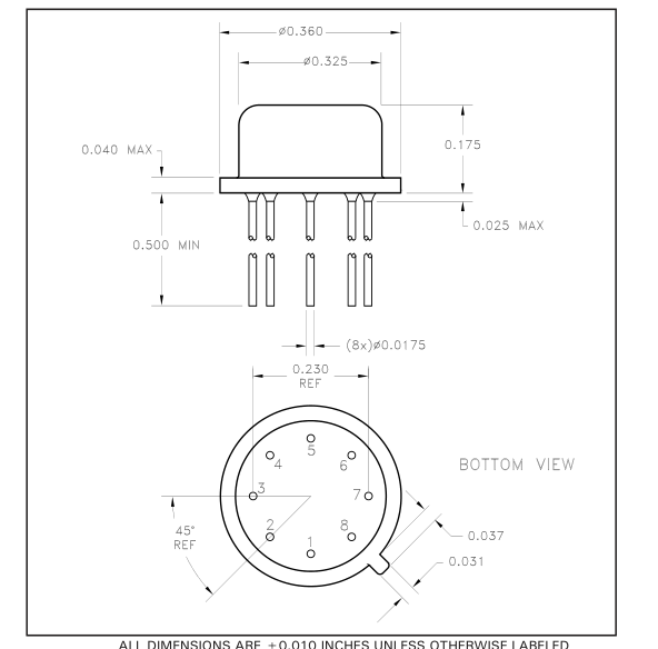
The MSK 0002 is a general purpose current amplifier. It is the industry wide replacement for the LH0002. The device is ideal for use with an operational amplifier in a closed loop configuration to increase current output. The MSK 0002 is designed with a symmetrical output stage that provides low output impedances to both the positive and negative portions of output pulses. The MSK 0002 is packaged in a hermetic 8 lead low profile T0-5 header and is specified over the full military temperature range.
EQUIVALENT SCHEMATIC
TYPICAL APPLICATIONS
High Speed D/A Conversion 30MHz Buffer Line Driver Precision Current Source
PIN-OUT INFORMATION
1 V1+
5 E4
2 V2+
6 V2- E3
V1-
Output
Input
CASE=ISOLATED
Page 2
5
ABSOLUTE MAXIMUM RATINGS
±VCC Supply Voltage
±22V
VIN Input Voltage
±22V
Pd Power Dissipation
600mW
Tc Case Operating Temperature
(MSK 0002H)
-55°C to +125°C
(MSK 0002)
-40°C to +85°C
ELECTRICAL SPECIFICATIONS
TST Storage Temperature Range -65°C to +150°C
TLD Lead Temperature Range
+300°C
(10 Seconds)
TJ Junction Temperature
+175°C
θjC Thermal Resistance @ TC=125°C
Output Devices
55°C/W
| Parameter Test Conditions 1 | Group A Subgroup | MSK 0002H 4 Min. Typ. Max. | MSK 0002 Min. Typ. Max. | Units | |
|---|---|---|---|---|---|
| VIN=0V Quiescent Current RS=10KΩ RL=1.0KΩ | 1 | - ±6.3 ±10 | - ±6.3 ±12 | mA | |
| Input Offset Current RS=10KΩ RL=1.0KΩ | 1 | - ±2 ±10 | - ±2 ±12 | μA | |
| 2,3 | - ±5 ±10 | - - - | μA | ||
| Input Offset Voltage RS=300Ω RL=1.0KΩ | 1 | - ±6 ±30 | - ±6 ±35 | mV | |
| 2,3 | - ±10 ±30 | - - - | mV | ||
| VIN=1.0VRMS RS=200KΩ Input Impedance 3 RL=1KΩ f=1.0KHz | 4 | 180 - - | 180 - - | KΩ | |
| VIN=1.0VRMS Rs=10KΩ Output Impedance 3 RL=50Ω f=1.0KHz | 4 | - - 10 | - - 10 | Ω | |
| Output Voltage Swing | VIN=±12Vp RL=1.0KΩ f=1.0KHz | 4 | ±10 ±11 - | ±10 ±11 - | Vp |
| VIN=±10Vp RL=100Ω +VCC=±15V f=1.0KHz | 4 | ±9.5 - - | ±9.5 - - | Vp | |
| VIN=3.0VPP f=1.0KHz Voltage Gain 2 RS=10KΩ RL=1.0KΩ | 4 | 0.95 0.97 - | 0.95 0.97 - | V/V | |
| 5,6 | 0.95 - - | - - - | V/V | ||
| VOUT=2.5VPP f=10KHz Rise Time RS=100Ω RL=50Ω | 4 | - 8 12 | - 8 15 | nS | |
NOTES:
1 Unless otherwise specified ±VCC=±12VDC 2 Subgroups 5 & 6 shall be tested as part of device initial characterization and after design and process changes. Parameter shall be guaranteed to the limits specified for subgroups 5 & 6 for all lots not specifically tested. 3 Devices shall be capable of meeting the parameter, but need not be tested. Subgroup 1,4 TA=TC=+25°C Subgroup 2,5 TA=TC=+125°C Subgroup 3,6 TA=TC=-55°C Continuous operation at or above absolute maximum ratings may adversly effect the device performance and/or life cycle.
Page 3
APPLICATION NOTES
HEAT SINKING
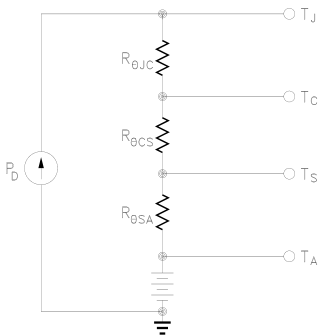
To determine if a heat sink is necessary for your application and if so, what type, refer to the thermal model and governing equation below.
Thermal Model:
Governing Equation:
TJ=PD X (RΘJC +RΘCS +RΘSA) +TA Where TJ=Junction Temperature PD=Total Power Dissipation RΘJC=Junction to Case Thermal Resistance RΘCS=Heat Sink to Ambient Thermal Resistance TC=Case Temperature TA=Ambient Temperature TS=Sink Temperature
Example:
This example demonstrates a worst case analysis for the buffer output stage. This occurs when the output voltage is 1/2 the power supply voltage. Under this condition, maximum power transfer occurs and the output is under maximum stress. Conditions: VCC= ±12VDC Vo= ±6Vp Sine Wave, Freq. = 1KHz RL= 100Ω
For a worst case analysis we will treat the ±6Vp sine wave as an 6 VDC output voltage.
1.) Find Driver Power Dissipation PD= (Vcc-Vo) (Vo/RL) = (12V-6V) (6V/100Ω) = 360mW 2.) For conservative design, set TJ=+125°C Max. 3.) For this example, worst case TA=+80°C 4.) RΘJC = 55° C/W from MSK 0002H Data Sheet 5.) RΘCS = 0.15° C/W for most thermal greases 6.) Rearrange governing equation to solve for RΘSA
RΘSA = ((TJ - TA)/PD) - (RΘJC) - (RΘCS) = ((125°C - 80°C) / 0.36W) - 55°C/W - 0.15°C/W = 125 - 55.15 = 69.9°C/W
This heat sink in this example must have a thermal resistance of no more than 69.9°C/W to maintain a junction temperature of no more than +125°C.
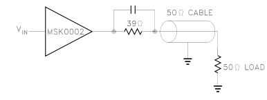
Typical Applications:
Page 4
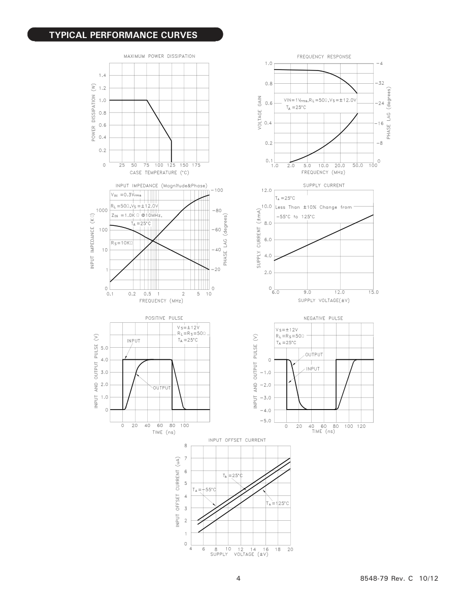
Page 5
MECHANICAL SPECIFICATIONS
ORDERING INFORMATION
| Part Number | Screening Level |
|---|---|
| MSK0002 | Industrial |
| MSK0002H | Mil-PRF-38534 Class H |
| 7801-301XC | DSCC-SMD |
M.S. Kennedy Corp.
4707 Dey Road, Liverpool, New York 13088
Phone (315) 701-6751 FAX (315) 701-6752 www.mskennedy.com
The information contained herein is believed to be accurate at the time of printing. MSK reserves the right to make changes to its products or specifications without notice, however, and assumes no liability for the use of its products.
Please visit our website for the most recent revision of this datasheet.