

 Download PDF
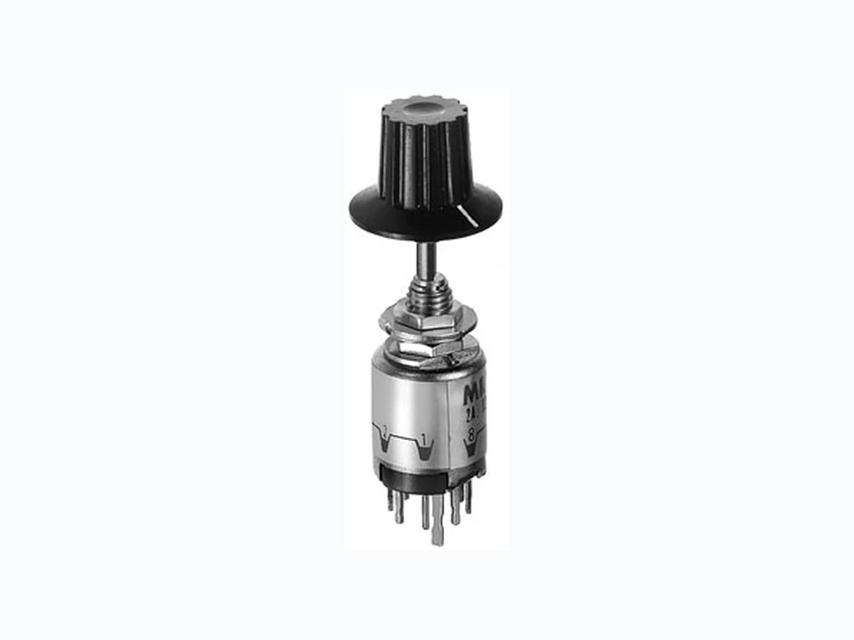
MRX108-AA NKK
Document overview
- PDF pages: 6
Technical content
Page 1
General Specifications
Electrical Capacity (Resistive Load)
For MRX: 2A @ 125V AC or 1A @ 30V DC For MRY: For MRY106G: 0.4VA maximum @ 28V AC/DC maximum (Applicable Range 0.1mA ~ 0.1A @ 20mV ~ 28V) Note: See Supplement Index to find explanation of operating range. For all other MRY models: 3A @ 125V AC or 2A @ 30V DC For MRT: For MRT22: 10A @ 125V AC or 4A @ 30V DC For MRT23: 5A @ 125V AC or 3A @ 30V DC
Other Ratings
Contact Resistance: 10 milliohms maximum for MRX, MRY, & MRT; 20 milliohms maximum for MRY106G Insulation Resistance: 100 megohms minimum @ 500V DC for MRX & MRY
200 megohms minimum @ 500V DC for MRT
Dielectric Strength: 1,000V AC minimum for 1 minute minimum Mechanical Life: 15,000 operations minimum Electrical Life: 7,500 operations minimum
Range of Operating Torque: 0.03 ~ 0.15Nm for MRX; 0.02 ~ 0.10Nm for MRY; 0.02 ~ 0.05Nm for MRT Contact Timing: Nonshorting (break-before-make)
MRX: Self-cleaning, sliding contact; MRY: Rotary contactor dish; MRT: Butt contacts
Indexing: 45° for MRX; 60° for MRY; 120° for MRT22; 60° for MRT23
Materials & Finishes
G
Shaft: Brass with nickel plating Stopper Plate: Steel with zinc plating for MRX & MRY Bushing/Housing: Brass with nickel plating Movable Contacts: Silver alloy for MRX & MRT; copper with silver plating for MRY106;
copper with gold plating for MRY106G
End Contacts & Terminals: Silver alloy & copper with silver plating for MRX & MRT; silver alloy plus brass with silver plating
for MRY106; silver alloy with gold plating for MRY106G
Common Contacts & Terminals: Copper with silver plating for MRX, MRY106 & MRT22; brass with gold plating for MRY106G;
brass with silver plating for MRT23 Base: Phenolic resin
Environmental Data
Operating Temperature Range: –10°C through +70°C (+14°F through +158°F)
Humidity: 90 ~ 95% humidity for 96 hours @ 40°C (104°F) Vibration: 10 ~ 55Hz with peak-to-peak amplitude of 1.5mm traversing the frequency range & returning in
1 minute; 3 right angled directions for 2 hours Shock: 50G (490m/s2) acceleration (tested in 3 right angled directions, with 3 shocks in each direction)
Installation
Mounting Torque: .686Nm (6.08 lb •in) Cap Installation Force: 19.6 ~ 29.4N (4.41 ~ 6.61 lbf) Soldering Time & Temperature: Manual Soldering: See Profile A in Supplement section.
Standards & Certifications
UL: File No. E44145 - Recognized only when ordered with marking on switch. Add “/U” or “/CUL” before dash in part number to order UL recognized switch. MRT22 models recognized at 10A @ 125V AC; MRT23 models recognized at 5A @ 125V AC
G22
Page 2
Distinctive Characteristics
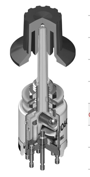
Positive detent mechanism for distinct feel and audible feedback.
Metal bushing and housing construction increases durability.
Adjustable stopper plate allows 2-8 position settings.
High contact reliability achieved by the self-cleaning contact mechanism.
Break-before-make contact timing with various mechanism types: sliding contacts in MRX, contactor dish in MRY, and butt contacts in MRT models.
G
Terminal types include PC-turret for MRX, turret for MRY, and solder lug for MRT models.
Molded-in PC-turret and turret terminals prevent entry of flux and other contaminants.
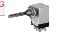
Actual Size
G23
Page 3
TYPICAL SWITCH ORDERING EXAMPLE
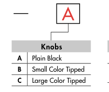
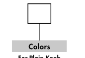
For Plain Knob
No Black Code For Color Tipped
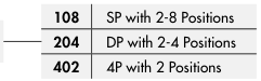
| 106 106G | SP with 2-6 Positions |
| SP with 2-6 Positions Gold Contacts 0.4VA |
Shaft Actuated with Y Turret Terminals
| 22 | DPDT ON-NONE-ON |
| 23 | DPDT ON-OFF-ON |
Shaft Actuated with T Solder Lug Terminals \*
\* Wire harness & cable assemblies offered only in Americas
G
IMPORTANT: MRT Switches are supplied without UL & cULus marking unless specified. UL & cULus recognized only when ordered with marking on the switch. Specific models, ratings, & ordering in- structions are noted on General Specifications page.
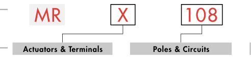
DESCRIPTION FOR TYPICAL ORDERING EXAMPLE
MRX108-A
Shaft Actuated with Plain Black Knob
SP with 2-8 Adjustable Positions
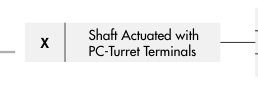
PC-Turret Terminals
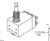
ACTUATORS & TERMINALS
Shaft Actuated with
Shaft Actuated with
Shaft Actuated with
T
Y
X
Turret Terminals
Solder Lug Terminals
PC-Turret Terminals
(2.3)
(2.3)
(2.3)
.091
.091
.091
1
6 1
(4.0)
8 1 (3.15) Dia
(3.15) Dia
.157
(5.0)
(5.0)
(2.0)
.124
.124
(20.0)
(20.0)
(20.0) .197
.197
.079 (2.4)
.787
.787
.787
.094
(0.8)
(0.9)
(1.3) Dia
.031
.035
.051
(1.0)
(1.0)
(1.0)
Thk = (0.9)
Thk = (0.7)
.039
.039
.039
.035
.028
Shaft
Terminal
Shaft Terminal
Shaft Terminal
G24
Page 4
POLES & CIRCUITS
| Pole | Model | Number of Position | s Stopper Settings | Number of Terminals | Schematics |
|---|---|---|---|---|---|
| SP | MRX108 | 2-8 | 2, 3, 4, 5, 6, 7, 8 | 1 COM, 8 LOAD | A 1 2 3 4 5 6 7 8 |
| MRY106 MRY106G | 2-6 | 2, 3, 4, 5, 6 | 1 COM, 6 LOAD | A 1 2 3 4 5 6 | |
| DP | MRX204 | 2-4 | 2, 3, 4 | 2 COM, 8 LOAD | A B 1 2 3 4 1 2 3 4 |
| DPDT | MRT22 | 2 | ON-NONE-ON | 2-3 2-1 5-6 5-4 | 2 (COM) 5 1 3 4 6 |
| MRT23 | 3 | ON-OFF-ON | 2-3 OPEN 2-1 5-6 OPEN 5-4 | ||
| 4P | MRX402 | 2 | 1 & 2 | 4 COM, 8 LOAD | A B C D 1 2 1 2 1 2 1 2 |
POSITION SETTING FOR MRX & MRY MODELS
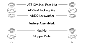
Mounting Hardware
G
Each switch is supplied with the stopper set for the maximum number of
Packaged Loose with Each Switch
positions allowed for that model. Prior to installation, the desired position
setting should be made. Contact factory for continuous rotation. 1. Using the actuator knob, turn the shaft counterclockwise to the extreme left. If the shaft is not turned to this extreme position where the white line on the knob points to the number 1 position shown on the side of the switch, proper setting cannot be achieved. 2. Remove the knob from the shaft and loosen the nut far enough to allow raising the stopper plate for resetting to the desired position. 3. Note the position numbers on the side of the switch; these correspond to the terminal numbers and stopper holes. Insert the stopper in the hole numbered for the maximum desired number of stop settings. Satisfactory
switch functioning cannot be assured if the stopper plate is not properly positioned.
MRX
MRY
- Tighten the nub (beveled side up) firmly against the stopper plate.
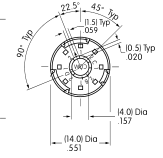
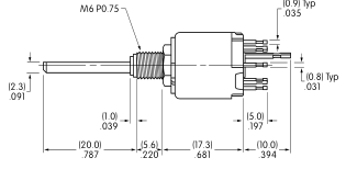
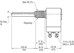
TYPICAL SWITCH DIMENSIONS
Single, Double & Four Pole
MRX • PC-Turret Terminals
5
COM
1
1
COM
MRX108
G25
Page 5
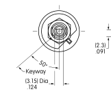
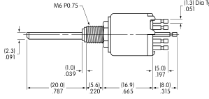
TYPICAL SWITCH DIMENSIONS
MRY • Turret Terminals
Single Pole
(3.15) Dia
6
.124
4 3 A (9.0) Dia
5
.354 O
2 6 1 (1.85) Dia Typ .073
18°
(14.0) Dia
Keyway
.551
MRY106
MRT • Solder Lug Terminals
Double Pole
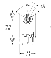
.124
3 2 1
(4.0) .157
MRT22
PC FOOTPRINTS FOR MRX SINGLE, DOUBLE, & FOUR POLE
p 22
22
. y
p . y
Double Pole
Single Pole
(1.98) Dia
(1.98) Dia Typ
.078 5
1 .078
4 6
4 2
A
A
(10.0) Dia
(10.0) Dia
.394
.394
3 7
3 3 B
2 8
2 4 (1.32) Dia Typ
1
1
(1.32) Dia Typ
(4.5) Dia
.052 (4.5) Dia
.052
.177
.177
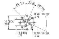
Four Pole
G26
Page 6
KNOBS
AT4103 Small
AT4104 Large
AT433
B
C
A
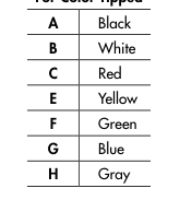
Color Tipped
Color Tipped
Plain Black
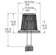
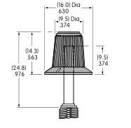
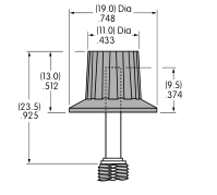
Base Material: Polyester
Base Material: Polyester
Material: Polyacetal
Base Color: Black
Base Color: Black
Color: Black only
Polyamide Tip
Polyamide Tip Colors: A, B, C, E, F, G, H
Colors: A, B, C, E, F, G, H
F
G
H
A
B
C
E
Color Codes:
Black
White
Red
Yellow
Green
Blue
Gray
G
PANEL CUTOUTS & MAXIMUM EFFECTIVE PANEL THICKNESS
Without
With
Maximum Effective Panel Thickness
Keyway
Keyway
With Standard Hardware: MRX & MRY .095” (2.4mm); MRT .106” (2.7mm) (5.6) .220 Without Locking Ring: MRX & MRY .126” (3.2mm); MRT .138” (3.5mm)
(6.5)
(6.35) Dia
(6.35) Dia
.256
(0.6)
.250
.250 .024
(2.2) Dia .087
G27