
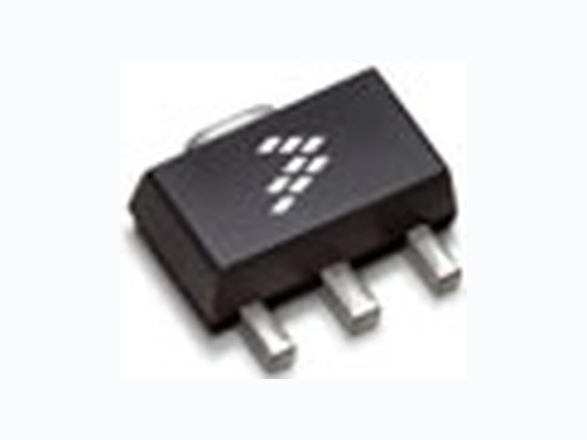
MMG15241H NXP
Document overview
- Manufacturer or author: Provided By www.digicamel.com(FREE DATASHEET DOWNLOAD SITE)
- PDF pages: 18
Technical content
Features
Frequency: 500- -2800 MHz Noise Figure: 1.6 dB @ 2140 MHz P1dB: 24 dBm @ 2140 MHz Small- -Signal Gain: 15.9 dB @ 2140 MHz Third Order Output Intercept Point: 39.4 dBm @ 2140 MHz Single 5 V Supply Supply Current: 85 mA 50 Ohm Operation (some external matching required) Cost- -effective SOT- -89 Surface Mount Plastic Package In Tape and Reel. T1 Suffix = 1,000 Units, 12 mm Tape Width, 7- -inch Reel. Table 1. Typical Performance(1)
- VDD =5V d c ,TA =2 5C, 50 ohm system, application circuit
tuned for specified frequency. Table 2. Maximum Ratings Table 3. Thermal Characteristics Select Documentation/Application Notes - - AN1955. Freescale Semiconductor, Inc., 2010–2011, 2014.All rights reserved.
Freescale Semiconductor, Inc. Table 4. Electrical Characteristics(VDD = 5 Vdc, 2140 MHz, TA =2 5C, 50 ohm system, in Freescale Application Circuit) Table 5. Functional Pin Description
1 RFin
2 Ground
3 RFout/DC Supply
Table 6. ESD Protection Characteristics Table 7. Moisture Sensitivity Level Figure 1. Functional Diagram
Freescale Semiconductor, Inc.
50 OHM TYPICAL CHARACTERISTICS
Figure 2. Small- -Signal Gain (S21) versus Figure 3. Input/Output Return Loss versus
- Test fixture characteristics have been mathematically removed from the graphical data.
Freescale Semiconductor, Inc.
50 OHM APPLICATION CIRCUIT: 2140 MHz
Figure 4. MMG15241HT1 Test Circuit Schematic Table 8. MMG15241HT1 Test Circuit Component Designations and Values
Freescale Semiconductor, Inc. Figure 5. MMG15241HT1 Test Circuit Component Layout
Freescale Semiconductor, Inc.
50 OHM TYPICAL CHARACTERISTICS: 2140 MHz
Figure 6. Small- -Signal Gain (S21) versus Figure 7. Input Return Loss (S11) versus Figure 8. Output Return Loss (S22) versus Figure 9. P1dB versus Frequency Figure 10. Third Order Output Intercept Figure 11. Noise Figure versus Frequency
Freescale Semiconductor, Inc. Figure 12. Single- -Carrier W- -CDMA Adjacent
3.84 MHz Channel Bandwidth, Input Signal
Freescale Semiconductor, Inc.
50 OHM APPLICATION CIRCUIT: 900 MHz
Figure 13. MMG15241HT1 Test Circuit Schematic Table 9. MMG15241HT1 Test Circuit Component Designations and Values Figure 14. MMG15241HT1 Test Circuit Component Layout
Freescale Semiconductor, Inc.
50 OHM TYPICAL CHARACTERISTICS: 900 MHz
Figure 15. Small- -Signal Gain (S21) versus Figure 16. Input Return Loss (S11) versus Figure 17. Output Return Loss (S22) versus Figure 18. P1dB versus Frequency Figure 19. Third Order Output Intercept Figure 20. Noise Figure versus Frequency
Freescale Semiconductor, Inc.
50 OHM APPLICATION CIRCUIT: 2600 MHz
Figure 21. MMG15241HT1 Test Circuit Schematic Table 10. MMG15241HT1 Test Circuit Component Designations and Values
Freescale Semiconductor, Inc. Figure 22. MMG15241HT1 Test Circuit Component Layout
Freescale Semiconductor, Inc.
50 OHM TYPICAL CHARACTERISTICS: 2600 MHz
Figure 23. Small- -Signal Gain (S21) versus Figure 24. Input Return Loss (S11) versus Figure 25. Output Return Loss (S22) versus Figure 26. P1dB versus Frequency Figure 27. Third Order Output Intercept Figure 28. Noise Figure versus Frequency
Freescale Semiconductor, Inc. MMG15241HT1 PACKAGE DIMENSIONS
Freescale Semiconductor, Inc.
Freescale Semiconductor, Inc. MMG15241HT1
Freescale Semiconductor, Inc. PRODUCT DOCUMENTATION, TOOLS AND SOFTWARE Refer to the following resources to aid your design process. Application Notes AN1955: Thermal Measurement Methodology of RF Power Amplifiers Software .s2p File Development Tools Printed Circuit Boards For Software and Tools, do a Part Number search at http://www.freescale.com, and select the “Part Number” link. Go to Software & Tools on the part’s Product Summary page to download the respective tool. FAILURE ANALYSIS At this time, because of the physical characteristics of the part, failure analysis is limited to electrical signature analysis. In cases where Freescale is contractually obligated to perform failure analysis (FA) services, full FA may be performed by third party vendors with moderate success. For updates contact your local Freescale Sales Office.
REVISION HISTORY
The following table summarizes revisions to this document. Revision Date Description 0 Dec. 2010 Initial Release of Data Sheet 1 Apr. 2011 Table 2, Maximum Ratings, updated RF Input Power from 13 dBm to 23 dBm as a result of new measurements done over temperature and bias, p. 1 2 Sept. 2014 Table 2, Maximum Ratings: updated Junction Temperature from 150C to 175C to reflect recent test results of the device, p. 1 Table 6, ESD Protection Characteristics: Changed ESD Human Body Model rating from 2 to 1A and Machine Model rating from B to A to reflect recent ESD test results of the device; removed the word “Minimum” after the ESD class rating. ESD ratings are characterized during new product development but are not 100% tested during production. ESD ratings provided in the data sheet are intended to be used as a guideline when handling ESDsensitive devices, p. 2 Revised Failure Analysis information, p. 17
Freescale Semiconductor, Inc. MMG15241HT1 Information in this document is provided solely to enablesystem and software implementers to use Freescale products. There are no express or implied copyright licenses granted hereunder to design or fabricate any integrated circuits based on the information in this document. Freescale reserves the right to make changes without further notice to any products herein. Freescale makes no warranty, representation, or guarantee regarding the suitability of its products for any particularpurpose, nor does Freescale assume any liability arisingout of the application or use of any product or circuit, and specifically disclaims any and all liability, including without limitation consequential or incidental damages. “Typical” parameters that may be provided in Freescale data sheets and/or specifications can and do vary in different applications, and actual performance may vary over time. All operating parameters, including “typicals,” must be validated for each customer application by customer’s technical experts. Freescale does not convey any license under its patent rights nor the rights of others. Freescale sells products pursuant to standard terms and conditions of sale, which can be found at the following address: freescale.com/SalesTermsandConditions. Freescale and the Freescale logo are trademarks of Freescale Semiconductor, Inc., respective owners. E 2010- -2011, 2014 Freescale Semiconductor, Inc. How to Reach Us: Home Page: freescale.com Web Support: freescale.com/support Document Number: MMG15241H Rev. 2, 9/2014