
DATASHEET SEARCH SITE
Document overview
- Manufacturer or author: Provided By digicamel.com
- PDF pages: 5
Technical content
SURFACE MOUNT HIGH VOLTAGE SWITCHING DIODE ARRAY
FEATURES
APPLICATIONS
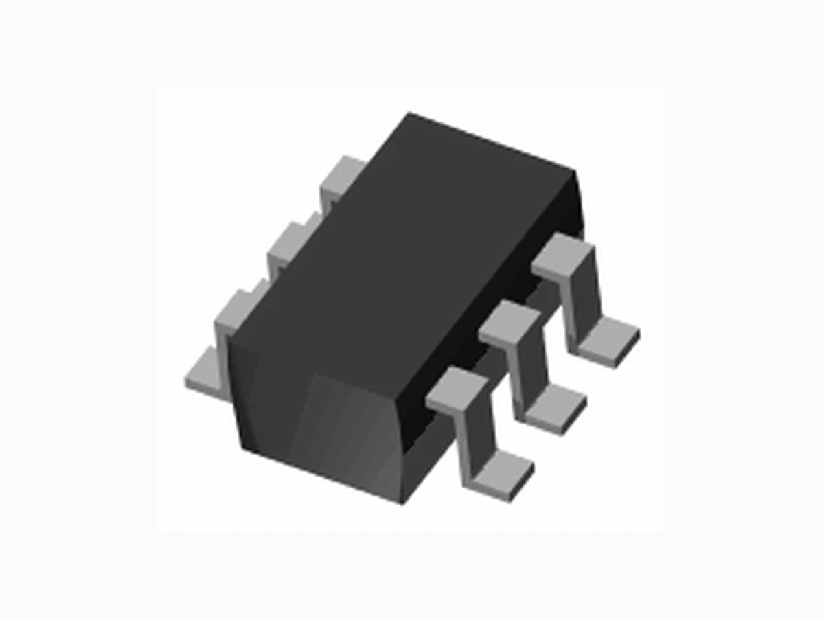
MAXIMUM RATINGS (Per Diode) Rating Symbol Value Units This device features two series-connected diode pairs which can be connected to form a full-wave bridge. It is housed in a very small SOT surface mount package. Repetitive Peak Reverse Voltage Continuous Reverse Voltage Continuous Forward Current (Note 1) Non-repetitive Peak Forward Current, t = 1sec, Square Wave Total Power Dissipation (Note 1) Operating Junction Temperature Range Storage Temperature Range May 19,2016REV.03 Page 1 www.panjit.com 350 V V 300 mA 225 A 1.0 350 mW -55 to +150 -55 to +150 V V I I P T T RRM R F FSM tot stg T = 25°C Unless otherwise noted J J SOT - 23 6L THERMAL CHARACTERISTICS Characteristic Symbol Units thjaThermal Resistance, Junction to Ambient (Note 1) 357 Value R °C/W Marking Code: B34 RMS Reverse Voltage 212 V VRMS Peak Repetitive Forward Current (Note 1) mA 625 I FRM 12 3 12 3 High Reverse Voltage Rating Lead free in compliance with EU RoHS 2011/65/EU directive Fast Switching Speed Low Capacitance Green molding compound as per IEC61249 Std. . (Halogen Free)
www.panjit.comMay 19,2016REV.03 Page 2 ELECTRICAL CHARACTERISTICS (Per Diode) Parameter Symbol Min Units Breakdown Voltage (Note 1) Tj = 25°C Unless otherwise noted Conditions Typ Max VBR BRI = Forward Voltage (Note 1) VF I = I = F F Reverse Leakage Current (Note 1) IR RV = Total Capacitance CT 0Vdc Bias, f =1 MHz Reverse Recovery Time t rr I = I =30mA, I = 3mA R = 100 ohms F R L 150uA 20mA 100mA 240V 350 - - V - 0.82 0.87 - 0.95 1.0 V 0.02 0.1 5.0 pF - 1.7 -5 0n s MMBD3004BRM Note 1. Short duration pulse test to avoid self-heating effect RR I =F 200mA 1.25 - 1.0 RV = 240V 0.5 100 - uA T =150°CJ 100 1000 Forw ard Voltage, V F (V) Forward Current, IF (mA) TJ = 25°C TJ = 75°C TJ = 150°C Fig. 1. Typical Forward Characteristics 100 1000 Forw ard Voltage, V F (V) Forward Current, IF (mA) TJ = 25°C TJ = 75°C TJ = 150°C Fig. 1. Typical Forward CharacteristicsFig. 1. Typical Forward Characteristics 0.2 0.4 0.6 0.8 1.2 1.4 1.6 1.8 0.1 1 10 100 Reverse Voltage, V R (V) Total Capacitance, C T (pF) f=1M H z Fig. 3. Typical Capacitance 0.2 0.4 0.6 0.8 1.2 1.4 1.6 1.8 0.1 1 10 100 Reverse Voltage, V R (V) Total Capacitance, C T (pF) f=1M H z Fig. 3. Typical CapacitanceFig. 3. Typical Capacitance 100 1000 100 200 300 Re ve r s e V oltage , VR (V) Reverse Current, IR (nA) TJ = 25°C TJ = 75°C TJ = 150°C Fig. 2. Typical Reverse Characteristics 100 1000 100 200 300 Re ve r s e V oltage , VR (V) Reverse Current, IR (nA) TJ = 25°C TJ = 75°C TJ = 150°C Fig. 2. Typical Reverse CharacteristicsFig. 2. Typical Reverse Characteristics
www.panjit.com Page 3May 19,2016REV.03
ORDERING INFORMATION
MMBD3004BRM T/R7 - 7" reel, 3K units per reel. Pin 1 towards tape sprocket holes MMBD3004BRM T/R7R - 7" reel, 3K units per reel. Pin 1 away from tape sprocket holes PACKAGE LAYOUT AND SUGGESTED PAD DIMENSIONS MMBD3004BRM MMBD3004BRM T/R13 -13" reel, 10K units per reel. Pin 1 towards tape sprocket holes MMBD3004BRM T/R13R - 13" reel, 10K units per reel. Pin 1 away from tape sprocket holes SOT-23 6LSOT-23 6L Uni t : inch( mm) 0.119(3.00) 0.110(2.80) 0.067(1.70) 0.059(1.50) 0.119(3.00) 0.102(2.60) 0.024(0.60) 0.012(0.30) GAUGE PLANE SEATING PLANE 0.020(0.50) 0.012(0.30) 0.057(1.45) MAX. 0.051(1.30) 0.035(0.90) 0.006(0.15) MAX. 0.009(0.22) 0.003(0.08) 0.01(0.25) BSC 0.075(1.90) BSC
PAGE . 4 Part No_packing code_Version MMBD3004BRM_R1_00001 MMBD3004BRM_R2_00001 MMBD3004BRM_S1_00001 MMBD3004BRM_S2_00001 For example : RB500V-40 00001 Part No. Serial number Version code means HF Packing size code means 13" Packing type means T/R Packing Code XX Version Code XXXXX Packing type 1st Code Packing size code 2nd Code HF or RoHS 1st Code 2 nd~5th Code Tape and Ammunition Box (T/B) A N/A 0 HF 0 serial number Tape and Reel (T/R) R 7" 1 RoHS 1 serial number Bulk Packing (B/P) B 13" 2 Tube Packing (T/P) T 26mm X Tape and Reel (Right Oriented) (TRR) S 52mm Y Tape and Reel (Left Oriented) (TRL) L PANASERT T/B CATHODE UP (PBCU) U FORMING F PANASERT T/B CATHODE DOWN (PBCD) D May 19,2016REV.03 MMBD3004BRM
PAGE . 5 Disclaimer
- Reproducing and modifying information of the document is prohibited without permission from Panjit International Inc..
- Panjit International Inc. reserves the rights to ma ke changes of the content here in the document anytime without notification. Please refer to our website f or the latest document. Panjit International Inc. disclaims any and all liability arising out of the a pplication or use of any product including da mages incidentally and consequentially occurred.
- Panjit International Inc. does not a ssume any and all implied warranties, including warranties of fitness for particular purpose, non-infringement and merchantability.
- Applications shown on the herein document are exa mples of standard use and operation. Customers are responsible in comprehending the suitable use in particular a pplications. Panjit International Inc. makes no representation or warranty that such a pplications will be suitable for the specified use without further testing or modification.
- The products shown herein are not designed and authorized for equipments requiring high level of reliability or relating to huma n life and for any applications concerning life-saving or life-sustaining, such a s medical instruments, transportation equipment, aerospace machinery et cetera. Customers using or selling the se products for use in such a pplications do so at their own risk and agree to fully inde mnify Panjit International Inc. for any damages resulting from such improper use or sale.
- Since Panjit uses lot number as the tracking base, please provide the lot number for tracking when complaining. May 19,2016REV.03 MMBD3004BRM