
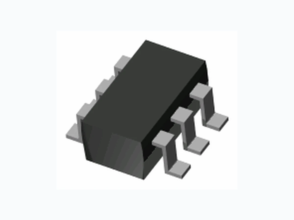
MMBD3004BRM PANJIT
Document overview
- Manufacturer or author: Provided By digicamel.com
- PDF pages: 3
Technical content
SURFACE MOUNT HIGH VOLTAGE SWITCHING DIODE ARRAY
FEATURES
APPLICATIONS
MAXIMUM RATINGS (Per Diode) Rating Symbol Value Units This device features two series-connected diode pairs which can be connected to form a full-wave bridge. It is housed in a very small SOT23-6L surface mount package. High Reverse Voltage Rating 100% Matte Tin Finish (LEAD-FREE PRODUCT) Fast Switching Speed Low Capacitance Power Supplies High Speed Rectification Repetitive Peak Reverse Voltage Continuous Reverse Voltage Continuous Forward Current (Note 1) Non-repetitive Peak Forward Current, t = 1sec, Square Wave Total Power Dissipation (Note 1) Operating Junction Temperature Range Storage Temperature Range 12/7/2005 Page 1 www.panjit.com 350 V V300 mA225 A1.0 350 mW °C-55 to +150 °C-55 to +150 V V I I P T T RRM R F FSM tot stg T = 25°C Unless otherwise noted J J SOT23-6L THERMAL CHARACTERISTICS Characteristic Symbol Units thjaThermal Resistance, Junction to Ambient (Note 1) 357 Value R °C/W Marking Code: 304 RMS Reverse Voltage 212 VVRMS Peak Repetitive Forward Current (Note 1) mA625I FRM 12 3 65 4 12 3 65 4
www.panjit.com12/7/2005 Page 2 ELECTRICAL CHARACTERISTICS (Per Diode) Parameter Symbol Min Units Breakdown Voltage (Note 1) Tj = 25°C Unless otherwise noted Conditions Typ Max VBR BR I = Forward Voltage (Note 1) VF I = I = F F Reverse Leakage Current (Note 1) IR RV = Total Capacitance CT 0Vdc Bias, f =1 MHz Reverse Recovery Time t rr I = I =30mA, I = 3mA R = 100 ohms F R L 150uA 20mA 100mA 240V 350 - - V - 0.82 0.87 - 0.95 1.0 V 0.02 0.1- 5.0 pF- 1.7 -5 0n s- MMBD3004BRM Note 1. Short duration pulse test to avoid self-heating effect RR I =F 200mA 1.25- 1.0 RV = 240V 0.5 100- uA T =150°CJ 100 1000 Forw ard Voltage, V F (V) Forward Current, IF (mA) TJ = 25°C TJ = 75°C TJ = 150°C Fig. 1. Typical Forward Characteristics 100 1000 Forw ard Voltage, V F (V) Forward Current, IF (mA) TJ = 25°C TJ = 75°C TJ = 150°C Fig. 1. Typical Forward CharacteristicsFig. 1. Typical Forward Characteristics 0.2 0.4 0.6 0.8 1.2 1.4 1.6 1.8 0.1 1 10 100 Reverse Voltage, V R (V) Total Capacitance, C T (pF) f=1M H z Fig. 3. Typical Capacitance 0.2 0.4 0.6 0.8 1.2 1.4 1.6 1.8 0.1 1 10 100 Reverse Voltage, V R (V) Total Capacitance, C T (pF) f=1M H z Fig. 3. Typical CapacitanceFig. 3. Typical Capacitance 100 1000 0 100 200 300 Re ve r s e V oltage , VR (V) Reverse Current, IR (nA) TJ = 25°C TJ = 75°C TJ = 150°C Fig. 2. Typical Reverse Characteristics 100 1000 0 100 200 300 Re ve r s e V oltage , VR (V) Reverse Current, IR (nA) TJ = 25°C TJ = 75°C TJ = 150°C Fig. 2. Typical Reverse CharacteristicsFig. 2. Typical Reverse Characteristics
www.panjit.com8/25/2005 Page 3
ORDERING INFORMATION
MMBD3004BRM T/R7 - 7" reel, 3K units per reel. Pin 1 towards tape sprocket holes MMBD3004BRM T/R7R - 7" reel, 3K units per reel. Pin 1 away from tape sprocket holes Copyright PanJit International, Inc 2005 The information presented in this document is believed to be accurate and reliable. The specifications and information herein are subject to change without notice. Pan Jit makes no warranty, representation or guarantee regarding the suitability of its products for any particular purpose. Pan Jit products are not authorized for use in life support devices or systems. Pan Jit does not convey any license under its patent rights or rights of others. PACKAGE LAYOUT AND SUGGESTED PAD DIMENSIONS MMBD3004BRM MMBD3004BRM T/R13 -13" reel, 10K units per reel. Pin 1 towards tape sprocket holes MMBD3004BRM T/R13R - 13" reel, 10K units per reel. Pin 1 away from tape sprocket holes