

 Download PDF
DATASHEET SEARCH SITE
Document overview
- PDF pages: 3
Technical content
Page 1
GENERAL DESCRIPTION
Faster semiconductor clock speeds and an increasing reliance on batteries as power
sources have resulted in the need for varistors that exhibit very low leakage current.
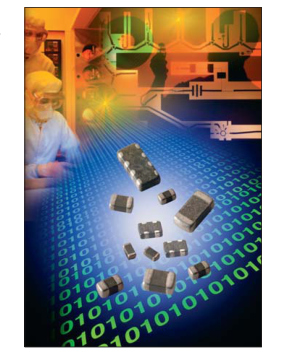
The UltraGuard (UG) Series of AVX Transient Voltage Suppressors address this
problem. The UG Series is the ideal transient protection solution for high clock speed integrated
circuit application, battery-operated device, backlit display, medical/instrument applica-
tion, low voltage power conversion circuits and power supervisory chip sets. In addi-
tion, UltraGuard’s low leakage characteristics are also suitable for optic circuits like
LDD, SerDes, and laser diodes. The UG Series is offered as discrete chips (0402, 0603, and 0805), 2-element pack-
ages (0405 and 0508), and 4-element packages (0612).
HOW TO ORDER
VC
UG
04
0180
Series
Case Size
Maximum
VC=Surface
Working
Mount Chip
UG = Low
04 = 0402
Voltage
Leakage
06 = 0603
0030 = 3.0VDC
Series
08 = 0805
0050 = 5.0VDC 0075 = 7.5VDC 0100 = 10.0VDC 0150 = 15.0VDC 0180 = 18.0VDC
HOW TO ORDER
MG
UG
06
0150
Series
Case Size
Maximum
MG=Array
Working
UG = Low
04 = 0405
Voltage
Leakage
05 = 0508
0030 = 3.0VDC
Series
06 = 0612
0050 = 5.0VDC 0075 = 7.5VDC 0100 = 10.0VDC 0150 = 15.0VDC
Discrete Chips
2-Element Arrays
4-Element Arrays
0402, 0603,
(0405 and 0508)
(0612)
and 0805
L
1
W
P
Capacitance
No. of
Termination
Packaging
Elements
Finish
(pieces per
L = Low
P = Ni/Sn Alloy reel)
H = High
(Plated)
D = 1,000 (7" reel) R = 4,000 (7" reel) T = 10,000 (13" reel) W = 10,000 (7" reel, 0402 only)
L
4
D
P
Capacitance
No. of
Termination
Packaging
Elements
Finish
(pieces per
L = Low 2 = 2 Elements
P = Ni/Sn Alloy reel)
H = High 4 = 4 Elements
(Plated)
D = 1,000 (7" reel) R = 4,000 (7" reel) T = 10,000 (13" reel)
Page 2
| AVX Part Number | V (DC) CIR | V (AC) CIR | Cap Required | Cap | Freq | I L | Case Size | Elements | |
|---|---|---|---|---|---|---|---|---|---|
| MGUG040030L2 _ _ | ≤3.0 | ≤2.3 | Low | 300 | M | 2 | 0405 | 2 | |
| MGUG050030L2 _ _ | ≤3.0 | ≤2.3 | Low | 425 | M | 2 | 0508 | 2 | |
| MGUG060030L4 _ _ | ≤3.0 | ≤2.3 | Low | 425 | M | 2 | 0612 | 4 | |
| VCUG040030L1 _ _ | ≤3.0 | ≤2.3 | Low | 175 | M | 2 | 0402 | 1 | |
| VCUG060030L1 _ _ | ≤3.0 | ≤2.3 | Low | 750 | K | 2 | 0603 | 1 | |
| VCUG080030H1 _ _ | ≤3.0 | ≤2.3 | High | 3000 | K | 2 | 0805 | 1 | |
| VCUG080030L1 _ _ | ≤3.0 | ≤2.3 | Low | 1100 | K | 2 | 0805 | 1 | |
| VCUG120030H1 _ _ | ≤3.0 | ≤2.3 | High | 3000 | K | 2 | 1206 | 1 | |
| VCUG120030L1 _ _ | ≤3.0 | ≤2.3 | Low | 1200 | K | 2 | 1206 | 1 | |
| MGUG040050L2 _ _ | ≤5.0 | ≤3.5 | Low | 40 | M | 2 | 0405 | 2 | |
| MGUG050050L2 _ _ | ≤5.0 | ≤3.5 | Low | 425 | M | 2 | 0508 | 2 | |
| MGUG060050L4 _ _ | ≤5.0 | ≤3.5 | Low | 425 | M | 2 | 0612 | 4 | |
| VCUG040050L1 _ _ | ≤5.0 | ≤3.5 | Low | 175 | M | 2 | 0402 | 1 | |
| VCUG060050L1 _ _ | ≤5.0 | ≤3.5 | Low | 550 | K | 2 | 0603 | 1 | |
| VCUG080050L1 _ _ | ≤5.0 | ≤3.5 | Low | 750 | K | 2 | 0805 | 1 | |
| VCUG120050H1 _ _ | ≤5.0 | ≤3.5 | High | 1050 | K | 2 | 1206 | 1 | |
| VCUG120050L1 _ _ | ≤5.0 | ≤3.5 | Low | 600 | K | 2 | 1206 | 1 | |
| MGUG040075L2 _ _ | ≤7.5 | ≤5.3 | Low | 40 | M | 2 | 0405 | 2 | |
| MGUG050075L2 _ _ | ≤7.5 | ≤5.3 | Low | 425 | M | 2 | 0508 | 2 | |
| MGUG060075L4 _ _ | ≤7.5 | ≤5.3 | Low | 425 | M | 2 | 0612 | 4 | |
| VCUG040075L1 _ _ | ≤7.5 | ≤5.3 | Low | 100 | M | 2 | 0402 | 1 | |
| VCUG060075L1 _ _ | ≤7.5 | ≤5.3 | Low | 425 | K | 2 | 0603 | 1 | |
| VCUG080075H1 _ _ | ≤7.5 | ≤5.3 | High | 900 | K | 2 | 0805 | 1 | |
| VCUG080075L1 _ _ | ≤7.5 | ≤5.3 | Low | 325 | K | 2 | 0805 | 1 | |
| VCUG120075H1 _ _ | ≤7.5 | ≤5.3 | High | 1050 | K | 2 | 1206 | 1 | |
| VCUG120075L1 _ _ | ≤7.5 | ≤5.3 | Low | 600 | K | 2 | 1206 | 1 | |
| MGUG040100L2 _ _ | ≤10.0 | ≤7.1 | Low | 40 | M | 2 | 0405 | 2 | |
| MGUG050100L2 _ _ | ≤10.0 | ≤7.1 | Low | 225 | M | 2 | 0508 | 2 | |
| MGUG060100L4 _ _ | ≤10.0 | ≤7.1 | Low | 225 | M | 2 | 0612 | 4 | |
| VCUG040100L1 _ _ | ≤10.0 | ≤7.1 | Low | 65 | M | 2 | 0402 | 1 | |
| VCUG060100L1 _ _ | ≤10.0 | ≤7.1 | Low | 250 | K | 2 | 0603 | 1 | |
| VCUG080100H1 _ _ | ≤10.0 | ≤7.1 | High | 550 | K | 2 | 0805 | 1 | |
| VCUG080100L1 _ _ | ≤10.0 | ≤7.1 | Low | 225 | K | 2 | 0805 | 1 | |
| VCUG120100H1 _ _ | ≤10.0 | ≤7.1 | High | 900 | K | 2 | 1206 | 1 | |
| VCUG120100L1 _ _ | ≤10.0 | ≤7.1 | Low | 350 | K | 2 | 1206 | 1 | |
| MGUG040150L2 _ _ | ≤15.0 | ≤11 | Low | 50 | M | 2 | 0405 | 2 | |
| MGUG050150L2 _ _ | ≤15.0 | ≤11 | Low | 50 | M | 2 | 0508 | 2 | |
| MGUG060150L4 _ _ | ≤15.0 | ≤11 | Low | 75 | M | 2 | 0612 | 4 | |
| VCUG040150L1 _ _ | ≤15.0 | ≤11 | Low | 40 | M | 2 | 0402 | 1 | |
| VCUG060150L1 _ _ | ≤15.0 | ≤11 | Low | 155 | K | 2 | 0603 | 1 | |
| VCUG080150H1 _ _ | ≤15.0 | ≤11 | High | 250 | K | 2 | 0805 | 1 | |
| VCUG080150L1 _ _ | ≤15.0 | ≤11 | Low | 120 | K | 2 | 0805 | 1 | |
| VCUG120150H1 _ _ | ≤15.0 | ≤11 | High | 500 | K | 2 | 1206 | 1 | |
| VCUG040180L1 _ _ | ≤18.0 | ≤14 | Low | 30 | M | 1 | 0402 | 1 | |
| Termination Finish Code | |||||||||
Packaging Code
VCIR(DC) DC Circuit Voltage (V) VCIR(AC) AC Circuit Voltage (V) Cap Req Standard or Low Maximum Leakage Current at the Circuit Voltage (μA) IL Typical Capacitance (pF) @ frequency specified and 0.5 Vrms Cap Frequency at which capacitance is measured (K = 1kHz, M = 1MHz) Freq
Page 3
PHYSICAL DIMENSIONS
mm (inches)
| 0402 Discrete | 0603 Discrete | 0805 Discrete | |
| Length | 1.00 ±0.10 (0.040 ±0.004) | 1.60 ±0.15 (0.063 ±0.006) | 2.01 ±0.20 (0.079 ±0.008) |
| Width | 0.50 ±0.10 (0.020 ±0.004) | 0.80 ±0.15 (0.032 ±0.006) | 1.25 ±0.20 (0.049 ±0.008) |
| Thickness | 0.60 Max. (0.024 Max.) | 0.90 Max. (0.035 Max.) | 1.02 Max. (0.040 Max.) |
| Term Band Width | 0.25 ±0.15 (0.010 ±0.006) | 0.35 ±0.15 (0.014 ±0.006) | 0.71 Max. (0.028 Max.) |
| 0405 Array | 0508 Array | 0612 Array | |
| Length | 1.00 ±0.15 (0.039 ±0.006) | 1.25 ±0.20 (0.049 ±0.008) | 1.60 ±0.20 (0.063 ±0.008) |
| Width | 1.37 ±0.15 (0.054 ±0.006) | 2.01 ±0.20 (0.079 ±0.008) | 3.20 ±0.20 (0.126 ±0.008) |
| Thickness | 0.66 Max. (0.026 Max.) | 1.02 Max. (0.040 Max.) | 1.22 Max. (0.048 Max.) |
| Term Band Width | 0.36 ±0.10 (0.014 ±0.004) | 0.41 ±0.10 (0.016 ±0.004) | 0.41 ±0.10 (0.016 ±0.004) |
SOLDER PAD DIMENSIONS
mm (inches)
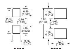
0.61 (0.024) 0.51
1.70 (0.067) (0.020) 0.61 (0.024)
0.51 (0.020)
0402
0603
0805
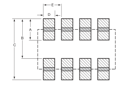
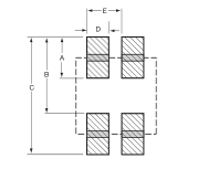
0612 4-Element Array
| A | B | C | D | E |
| 0.89 (0.035) | 1.65 (0.065) | 2.54 (0.100) | 0.46 (0.018) | 0.76 (0.030) |
2-Element Arrays
| A | B | C | D | E | |
| 0405 | 0.46 (0.018) | 0.74 (0.029) | 1.20 (0.047) | 0.38 (0.015) | 0.64 (0.025) |
| 0508 | 0.89 (0.035) | 1.27 (0.050) | 2.16 (0.085) | 0.46 (0.018) | 0.76 (0.030) |