
DATASHEET SEARCH SITE
Document overview
- Manufacturer or author: Provided By www.digicamel.com(FREE DATASHEET DOWNLOAD SITE)
- PDF pages: 21
Technical content
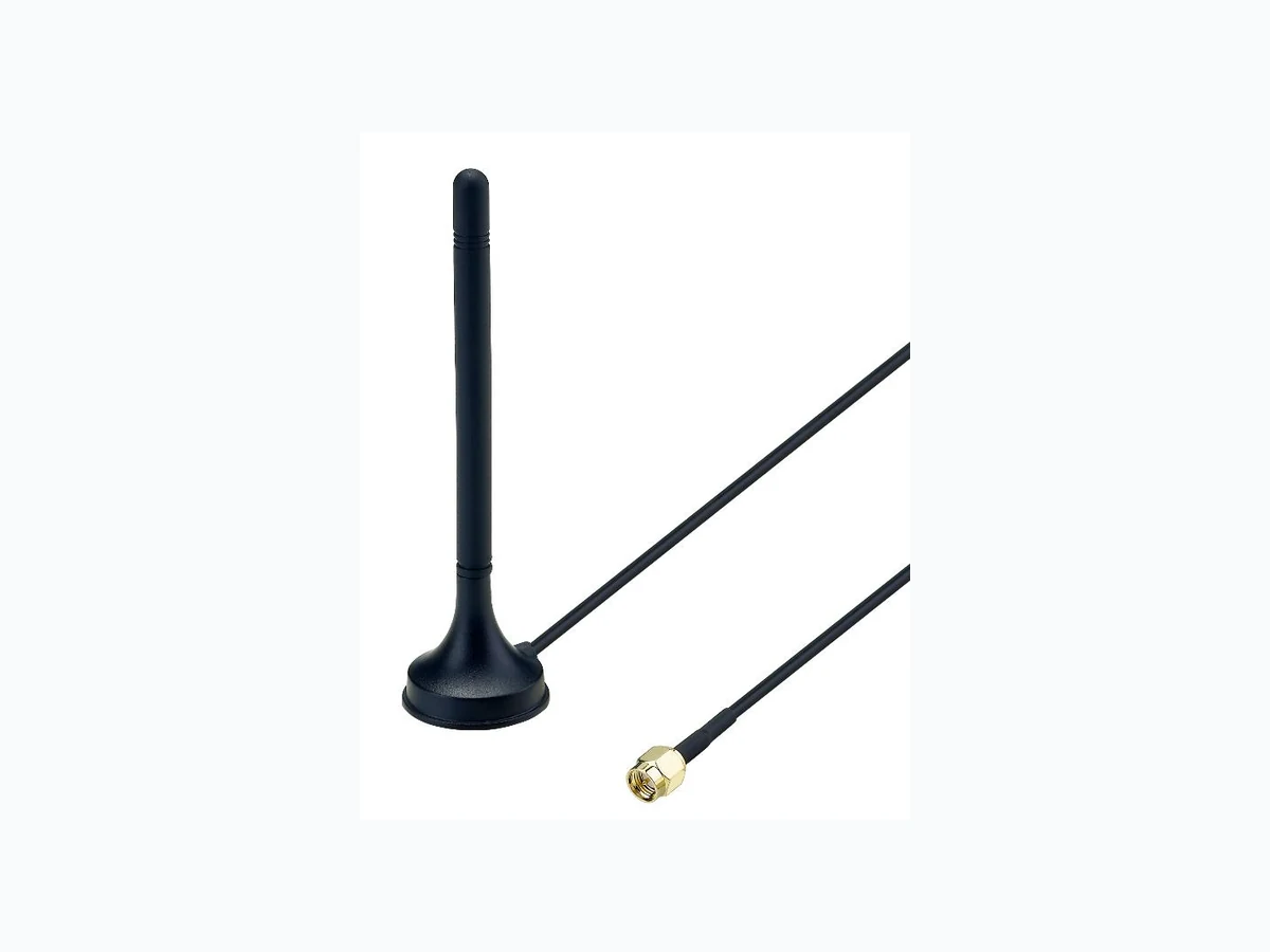
SPE-17-8-034/A Page 1 of 21 DRAFT SPECIFICATION Part No. : MGA1.101111 Product Name : CAT M1 3dBi Mini Magnetic Mount 698~960MHz/1710~2700MHz Features : 698MHz to 960MHz/1710MHz to 2700MHz Works on 4G/3G/2G 1M RG174 Cable, SMA(M) Connector Typical 30%+ Efficiency and 3dBi Peak Gain Robust High Strength Magnet Mount Custom cables and connectors available RoHS compliant
SPE-17-8-034/A Page 2 of 21 1. Introduction The MGA1.101111 magnetic mount antenna delivers stable high omnidirectional gain and efficiencies to support CAT M1 application bands and all common 4G/3G/2G global cellular bands from 698 MHz to 2.7 GHz. Category (CAT) M1 is a low power wide area (LPWA) technology specifically designed for IoT and M2M. CAT M1 technology offers lower maintenance cost, with greater efficiency and reliability by reducing power consumption and providing deeper penetration compared to standard cellular technologies. It operates on secure mobile networks making it suited to a utomotive, s mart meter, me dical and smart city applications. This high performing antenna can be used for all cellular devices and will not require changing antennas when deploying from country to country or technology to technology like CDMA to GSM. Being magnetic mount it is designed to be mounted on a ground plane for optimal performance. A reliable return loss of < 5dB when mounted on a metal plate ensures it complies with the industry standards set by module makers and networks worldwide. Taoglas recommends using the antenna w ith 1m cable length or less and can provide customized connectors and cable lengths upon customer requirements. The strong magnet base is extremely stable and robust, using only high quality neodymium magnets for a secure magnetic mount to ensure a high pull force to disengage.
SPE-17-8-034/A Page 3 of 21 2. Specification CAT M1 Frequency(MHz) Band 2 Band 4 Band 12 Tx Rx Tx Rx Tx Rx 1850-1910 1930-1990 1710-1755 2110-2155 699-716 729-746 Efficiency (%) Average Gain (dBi) Peak Gain (dBi) Impedance 50Ω Polarization Linear Cable 1 Meter RG-174 Coaxial Cable Connector SMA (M) MECHNICAL Antenna Dimension 7.8 x 30 x 82.8 mm Housing Material TPEE and ABS Cable 1 Meter RG-174 Coaxial Cable Connector SMA (M) Magnetic Pull Force 2 kgf
SPE-17-8-034/A Page 4 of 21 3. Antenna Characteristics 3.1. Antenna Test Setup In free space On 30x30cm Ground Center
SPE-17-8-034/A Page 5 of 21 3.2. Return Loss 3.3. Efficiency
SPE-17-8-034/A Page 6 of 21 3.4. Peak Gain 3.5. Average Gain
SPE-17-8-034/A Page 7 of 21 4. Antenna Radiation Patterns 4.1. Antenna Setup (Antenna testing Setup in Anechoic Chamber) In free space On 30x30 Ground Center Y X Z Y X Z
SPE-17-8-034/A Page 8 of 21 4.2. 2D Radiation Patterns 4.2.1. In free space XY Plane
SPE-17-8-034/A Page 9 of 21 XZ Plane
SPE-17-8-034/A Page 10 of 21 YZ Plane
SPE-17-8-034/A Page 11 of 21 4.2.2. On the 30x30cm Ground Center XY Plane
SPE-17-8-034/A Page 12 of 21 XZ Plane
SPE-17-8-034/A Page 13 of 21 YZ Plane
SPE-17-8-034/A Page 14 of 21 4.3. 3D Radiation Patterns 4.3.1. In free space
704 MHz 751 MHz
824 MHz 960 MHz
1710 MHz 1850 MHz
SPE-17-8-034/A Page 15 of 21
1990 MHz 2170 MHz
2500 MHz 2690 MHz
SPE-17-8-034/A Page 16 of 21 4.3.2. On the 30x30cm Ground Center
SPE-17-8-034/A Page 17 of 21
SPE-17-8-034/A Page 18 of 21 5. Magnetic Pull Force (Kilogram – force (kgf))
SPE-17-8-034/A Page 19 of 21 6. Mechanical Drawing (Unit: mm)
SPE-17-8-034/A Page 20 of 21 7. Packaging
SPE-17-8-034/A Page 21 of 21 Taoglas makes no warranties based on the accuracy or completeness of the contents of this document and reserves the right to make changes to specifications and product descriptions at any time without notice. Taoglas reserves all rights to this document and the information contained herein. Reproduction, use or disclosure to third parties without express permission is strictly prohibited. Copyright © Taoglas Ltd.