
MCU0402HP_V01 VISHAY
Document overview
- Manufacturer or author: Provided By www.digicamel.com(FREE DATASHEET DOWNLOAD SITE)
- PDF pages: 10
Technical content
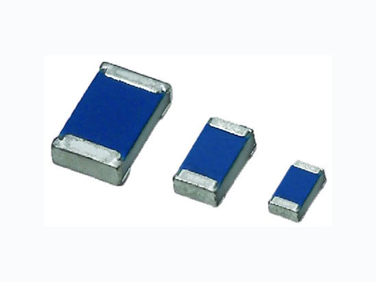
MCS 0402 HP, MCT 0603 HP, MCU 0805 HP www.vishay.com Vishay Beyschlag Revision: 28-Nov-17 1 Document Number: 28916 For technical questions, contact: thinfilmchip@vishay.com THIS DOCUMENT IS SUBJECT TO CHANGE WITHOUT NOTICE. THE PRODUCTS DESCRIBED HEREIN AND THIS DOCUMENT ARE SUBJECT TO SPECIFIC DISCLAIMERS, SET FORTH AT www.vishay.com/doc?91000 High Power Thin Film Chip Resistors Automotive grade high power MC HP thin film chip resistors are the perfect choice for most fields of modern electronics where high power dissipation, reliability and stability is of major concern. The permissible power rating is specified with up to 400 mW and allows replacement of larger case sizes with next smaller ones. Typical applications include power electronics in automotive and industrial appliances.
FEATURES
- Operating temperature up to 175 °C
- Rated dissipation up to 0.4 W for size 0805
- AEC-Q200 qualified
- Superior temperature cycling robustness
- Advanced sulfur re sistance verified according to ASTM B 809
- Material categorization: fo r definitions of compliance please see www.vishay.com/doc?99912
APPLICATIONS
- Automotive
- Industrial
- High power and high temperature applications
- Replacement for larger case sizes Note (1) Please refer to APPLICATION INFORMATION below
APPLICATION INFORMATION
When the resistor dissipates power, a te mperature rise above the ambient tempera ture occurs, depend ent on the thermal resistance of the assembled resistor together with the printed circuit board. The rated dissipation applies only if the permitted film temperature is not exceeded. These resistors do not feature a limited lifetime when operated within the permissibl e limits. However, re sistance value drift increasing over operating time may result in exceeding a limit acceptable to the specific application, thereby establishing a functional lifetime. TECHNICAL SPECIFICATIONS DESCRIPTION MCS 0402 HP MCT 0603 HP MCU 0805 HP Imperial size 0402 0603 0805 Metric size code RR1005M RR1608M RR2012M Resistance range 47 Ω to 100 kΩ 1 Ω to 100 kΩ 1 Ω to 100 kΩ Resistance tolerance ± 1 %; ± 0.5 %; ± 0.1 % Temperature coefficient ± 50 ppm/K; ± 25 ppm/K Rated dissipation P 85 (1) 0.200 W 0.250 W 0.400 W Operating voltage, Umax. ACRMS/DC 50 V 75 V 150 V Permissible film temperature, ϑF max. (1) 175 °C Operating temperature range -55 °C to 175 °C
MCS 0402 HP, MCT 0603 HP, MCU 0805 HP www.vishay.com Vishay Beyschlag Revision: 28-Nov-17 2 Document Number: 28916 For technical questions, contact: thinfilmchip@vishay.com THIS DOCUMENT IS SUBJECT TO CHANGE WITHOUT NOTICE. THE PRODUCTS DESCRIBED HEREIN AND THIS DOCUMENT ARE SUBJECT TO SPECIFIC DISCLAIMERS, SET FORTH AT www.vishay.com/doc?91000 Note
- The presented operation modes do not refer to different types of resistors, but actually show examples of different loads, tha t lead to different film temperatures and different achievable load-life st ability (drift) of the resistance value. A suitable low therma l resistance of the circuit board assemb ly must be safeguarded in order to maintain the film temperature of the resistors within the specified limi ts. Please consider the application note “Thermal Management in Surface-Mounted Resistor Applications” ( www.vishay.com/doc?28844 ) for information on the general nature of thermal resistance. MAXIMUM RESISTANCE CHANGE AT RATED DISSIPATION OPERATION MODE POWER ADVANCED TEMPERATURE P70 P85 Rated dissipation MCS 0402 HP 0.200 W 0.200 W MCT 0603 HP 0.250 W 0.250 W MCU 0805 HP 0.400 W 0.400 W Operating temperature range -55 °C to 155 °C -55 °C to 175 °C Permissible film temperature, ϑF max. 155 °C 175 °C Max. resistance change at rated dissipation for resistance range, |ΔR/R| after: MCS 0402 HP 47 Ω to 100 kΩ 47 Ω to 100 kΩ MCT 0603 HP 1 Ω to 100 kΩ 1 Ω to 100 kΩ MCU 0805 HP 1 Ω to 100 kΩ 1 Ω to 100 kΩ 8000 h ≤ 0.4 % - TEMPERATURE COEFFICIENT AND RESISTANCE RANGE TYPE / SIZE TCR TOLERANCE RESISTANCE E-SERIES MCS 0402 HP ± 50 ppm/K ± 1 % 47 Ω to 100 kΩ E24; E96 ± 25 ppm/K ± 0.5 % 47 Ω to 100 kΩ E24; E192 ± 0.1 % 47 Ω to 100 kΩ MCT 0603 HP ± 50 ppm/K ± 1 % 1 Ω to 100 kΩ E24; E96 ± 25 ppm/K ± 0.5 % 10 Ω to 100 kΩ E24; E192 ± 0.1 % 47 Ω to 100 kΩ MCU 0805 HP ± 50 ppm/K ± 1 % 1 Ω to 100 kΩ E24; E96 ± 25 ppm/K ± 0.5 % 10 Ω to 100 kΩ E24; E192 ± 0.1 % 47 Ω to 100 kΩ
MCS 0402 HP, MCT 0603 HP, MCU 0805 HP www.vishay.com Vishay Beyschlag Revision: 28-Nov-17 3 Document Number: 28916 For technical questions, contact: thinfilmchip@vishay.com THIS DOCUMENT IS SUBJECT TO CHANGE WITHOUT NOTICE. THE PRODUCTS DESCRIBED HEREIN AND THIS DOCUMENT ARE SUBJECT TO SPECIFIC DISCLAIMERS, SET FORTH AT www.vishay.com/doc?91000 Note (1) 1000 pieces packaging is available only for precision resistors with tolerance ± 0.1 % Note
- Products can be ordered using either the PART NUMBER or the PRODUCT DESCRIPTION PACKAGING TYPE / SIZE CODE QUANTITY PACKAGING ST YLE WIDTH PITCH PACKAGING DIMENSIONS MCS 0402 HP E1 1000 (1) Paper tape acc. IEC 60286-3, Type 1a 8 mm 2 mm Ø 180 mm / 7"E5 5000 E0 10 000 MCT 0603 HP P1 1000 (1) 4 mm Ø 180 mm / 7" P5 5000 PW 20 000 Ø 330 mm / 13" MCU 0805 HP P1 1000 (1) Ø 180 mm / 7" P5 5000 PW 20 000 Ø 330 mm / 13" PART NUMBER AND PRODUCT DESCRIPTION Part Number: MCT0603PD4641DPW00 TYPE / SIZE VERSION TCR RESISTANCE TOLERANCE PACKAGING MCS0402 MCT0603 MCU0805 P = HP (high power, automotive) D = ± 25 ppm/K C = ± 50 ppm/K 3 digit value 1 digit multiplier Multiplier 8 = *10-2 9 = *10-1 0 = *100 1 = *101 2 = *102 3 = *103 B = ± 0.1 % D = ± 0.5 % F = ± 1 % PW Product Description: MCT 0603-25 0.5 % HP PW 4K64 MCT 0603 -25 0.5 % HP PW 4K64 TYPE SIZE TCR TOLERANCE VERSION PACKAGING RESISTANCE MCS MCT MCU 0402 0603 0805 ± 25 ppm/K ± 50 ppm/K ± 0.1 % ± 0.5 % ± 1 % HP = high power automotive PW 4K64 = 4.64 kΩ CT0603P D4M 41D P W 006
MCS 0402 HP, MCT 0603 HP, MCU 0805 HP www.vishay.com Vishay Beyschlag Revision: 28-Nov-17 4 Document Number: 28916 For technical questions, contact: thinfilmchip@vishay.com THIS DOCUMENT IS SUBJECT TO CHANGE WITHOUT NOTICE. THE PRODUCTS DESCRIBED HEREIN AND THIS DOCUMENT ARE SUBJECT TO SPECIFIC DISCLAIMERS, SET FORTH AT www.vishay.com/doc?91000
DESCRIPTION
Production is strictly controlled and follows an extensive set of instructions establishe d for reproducibility. A homogeneous film of special me tal alloy is deposited on a high grade ceramic substrate (Al 2O3) and conditioned to achieve the desired temperature coefficient. Specially designed inner contacts are deposited on both sides. A special laser is used to achieve the target value by smoothly cutting a meander groove in the resistive layer without damaging the ceramics. The resistor elements are covered by a unique protective coating designed for electrical, mechanical and climatic protection. The terminations receive a final pure matte tin on nickel plating. The result of the determined production is verified by an extensive testing procedure and optical inspection performed on 100 % of the indi vidual chip resistors. This includes full screening for the elimination of products with potential risk of early field failures (feasible for R ≥ 10 Ω). Only accepted products are laid directly into the paper tape in accordance with IEC 60286-3 Type 1a (1). ASSEMBLY The resistors are suitable for processing on automatic SMD assembly systems. They are suitable for automatic soldering using wave, reflow or vapor phase as shown in IEC 61760-1 (1). The encapsulation is resistant to all cleaning solvents commonly used in the electronics industry, including alcohols, esters and aqueous solutions. The suitability of conformal coatings, potting compounds and their processes, if app lied, shall be qualified by appropriate means to ensure th e long-term stability of the whole system. The resistors are RoHS-compliant; the pure matte tin plating provides compatibility with lead (Pb)-free and lead-containing soldering processes. Solderability is specified for 2 years after production or requalification. The permitted storage time is 20 years. The immunity of the plating against tin whisker gr owth has been proven under extensive testing. MATERIALS Vishay acknowledges the following systems for the regulation of hazardous substances:
- IEC 62474, Material Declaration for Products of and for the Electrotechnical Industry, with the list of declarable substances given therein (2)
- The Global Automotive Declarable Substance List (GADSL) (3)
- The REACH regulation (1907/2006/EC) and the related list of substances with very high concern (SVHC) (4) for its supply chain The products do not contain any of the banned substances as per IEC 62474, GADSL, or the SVHC list, see www.vishay.com/how/leadfree. Hence the products fully comply with the following directives:
- 2000/53/EC End-of-Life Vehicle Directive (ELV) and Annex II (ELV II)
- 2011/65/EU Restriction of the Use of Hazardous Substances Directive (RoHS) with amendment 2015/863/EU
- 2012/19/EU Waste Electrical and Electronic Equipment Directive (WEEE) Vishay pursues the elimination of conflict minerals from its supply chain, see the Conflict Minerals Policy at www.vishay.com/doc?49037 APPROVALS Where applicable the resistors are tested within the IECQ-CECC Quality Assessment System for Electronic Components to the detail specification EN 140401-801 which refers to EN 60115-1, EN 60115-8 and the variety of environmental test procedures of the IEC 60068 (1) series. The resistors are qualified according to AEC-Q200. Vishay Beyschlag has achieved “Approval of Manufacturer” in accordance with IECQ 03-1. The release certificate for “Technology Approval Schedule” in accordance with CECC 240001 based on IECQ 03-3-1 is granted for the Vishay Beyschlag manufacturing process.
RELATED PRODUCTS
For high power and high temperature applications MCW AT wide terminal thin film chip resistors offer extremely high power ratings in compact 0406 and 0612 case size and extraordinary temperature cycling robustness. Please refer to the datasheets: MCW 0406 AT - Precision (www.vishay.com/doc?28847 ) and MCW 0406 AT, MCW 0612 AT - Professional (www.vishay.com/doc?28796). Notes (1) The quoted IEC standards are also released as EN standards with the same number and identical contents (2) The IEC 62474 list of declarable substances is maintained in a dedicated database, which is available at http://std.iec.ch/iec62474 (3) The Global Automotive Declarable Substance List (GADSL) is maintained by the American Chemistry Council and available at www.gadsl.org (4) The SVHC list is maintained by the European Chemical Agency (ECHA) and available at http://echa.europa.eu/candidate-list-table
MCS 0402 HP, MCT 0603 HP, MCU 0805 HP www.vishay.com Vishay Beyschlag Revision: 28-Nov-17 5 Document Number: 28916 For technical questions, contact: thinfilmchip@vishay.com THIS DOCUMENT IS SUBJECT TO CHANGE WITHOUT NOTICE. THE PRODUCTS DESCRIBED HEREIN AND THIS DOCUMENT ARE SUBJECT TO SPECIFIC DISCLAIMERS, SET FORTH AT www.vishay.com/doc?91000 FUNCTIONAL PERFORMANCE Derating - Power Operation Derating - Advanced Temperature Operation Maximum pulse load, single pulse; applicable if P → 0 and n ≤ 1000 and Û ≤ Ûmax.; for permissible resistance change ± (0.5 % R + 0.05 Ω) Single Pulse °C100 150-50 50 70 ϑAmbient Temperature amb 0 175 Power Dissipation P W 0.3 0.2 0.1 0.4 MCT 0603 HP MCU 0805 HP MCS 0402 HP Power Dissipation P °C100 150-50 50 ϑAmbient Temperature amb 0 85 175 W 0.3 0.2 0.1 0.4 MCT 0603 HP MCU 0805 HP MCS 0402 HP W Pulse Load max. 100 µs 1 ms 10 ms 1 s 10 s10 µs 100 ms Pulse Duration i 0.1 P t 100 MCT 0603 HP MCU 0805 HP MCS 0402 HP
MCS 0402 HP, MCT 0603 HP, MCU 0805 HP www.vishay.com Vishay Beyschlag Revision: 28-Nov-17 6 Document Number: 28916 For technical questions, contact: thinfilmchip@vishay.com THIS DOCUMENT IS SUBJECT TO CHANGE WITHOUT NOTICE. THE PRODUCTS DESCRIBED HEREIN AND THIS DOCUMENT ARE SUBJECT TO SPECIFIC DISCLAIMERS, SET FORTH AT www.vishay.com/doc?91000 Maximum pulse load, continuous pulses; applicable if P ≤ P (ϑamb) and Û ≤ Ûmax.; for permissible resistance change ± (0.5 % R + 0.05 Ω) Continuous Pulse Maximum pulse voltage, single and continuous pulses; applicable if ≤ max.; for permissible resistance change ± (0.5 % R + 0.05 Ω) Pulse Voltage Pulse load rating in accordance with EN 60115-1 clause 4.27; 1.2 μs/50 μs; 5 pulses at 12 s interval; for permissible resistance change ± (0.5 % R + 0.05 Ω) 1.2/50 Pulse W 100 100 µs 1 ms 10 ms 1 s 10 s10 µs 100 ms Pulse Duration 0.1 it Continuous Pulse Load max.P^ MCT 0603 HP MCU 0805 HP MCS 0402 HP 1 kV 100 µs 1 ms 10 ms 1 s 10 s 10 µs 100 ms 100 V 10 V Pulse Duration it Pulse Voltage max. Û MCT 0603 HP MCU 0805 HP MCS 0402 HP Pˆ Pˆ 100 V 1 kV 10 V 10 kV Resistance Value Test Voltage 100 /g58 1 k/g58 10 k /g58 100 k /g58 10 /g58 1 M/g58 R MCT 0603 HP MCU 0805 HP MCS 0402 HP
MCS 0402 HP, MCT 0603 HP, MCU 0805 HP www.vishay.com Vishay Beyschlag Revision: 28-Nov-17 7 Document Number: 28916 For technical questions, contact: thinfilmchip@vishay.com THIS DOCUMENT IS SUBJECT TO CHANGE WITHOUT NOTICE. THE PRODUCTS DESCRIBED HEREIN AND THIS DOCUMENT ARE SUBJECT TO SPECIFIC DISCLAIMERS, SET FORTH AT www.vishay.com/doc?91000 FUNCTIONAL PERFORMANCE Pulse load rating in accordance with EN 60115-1 clause 4.27; 10 μs/700 μs; 10 pulses at 1 min intervals; for permissible resistance change ± (0.5 % R + 0.05 Ω) 10/700 Pulse TESTS AND REQUIREMENTS All tests are carried out in accordance with the following specifications: EN 60115-1, generic specification EN 60115-8, sectional specification EN 140401-801, detail specification IEC 60068-2-xx, test methods The parameters stated in the Test Procedures and Requirements table are based on the required tests and permitted limits of EN 140401-801. The table presents only the most important tests, for the full test schedule refer to the documents listed above. However, some additional tests and a number of improvements against those minimum requirements have been included. The testing also covers most of the requirements specified by EIA/ECA-703 and JIS-C-5201-1. The tests are carried out under standard atmospheric conditions in accordance with IEC 60068-1, 4.3, whereupon the following values are applied: Temperature: 15 °C to 35 °C Relative humidity: 25 % to 75 % Air pressure: 86 kPa to 106 kPa (860 mbar to 1060 mbar) A climatic category LCT / UCT / 56 is applied, defined by the lower category temperature (LCT), the upper category temperature (UCT), and the du ration of exposure in the damp heat, steady state test (56 days). The components are mounted for testing on printed circuit boards in accordance with EN 60115-8, 2.4.2, unless otherwise specified. 100 V 1 kV 10 V 10 kV Resistance Value Test Voltage 100 Ω 1 kΩ 10 k Ω 100 k Ω 10 Ω 1 MΩ R MCT 0603 HP MCU 0805 HP MCS 0402 HP TEST PROCEDURES AND REQUIREMENTS EN 60115-1 CLAUSE IEC 60068-2 (1) TEST METHOD TEST PROCEDURE REQUIREMENTS PERMISSIBLE CHANGE (ΔR) Stability for product types: MCS 0402 HP 47 Ω to 100 kΩ MCT 0603 HP 1 Ω to 100 kΩ MCU 0805 HP 1 Ω to 100 kΩ 4.5 - Resistance - ± 1 % R; ± 0.5 % R; ± 0.1 % R 4.8 - Temperature coefficient At (20/-55/20) °C and 4.25.1 - Endurance at 70 °C: power operation mode U = or U = Umax.; whichever is the less severe; 1.5 h on; 0.5 h off; Endurance at 85 °C: advanced temperature operation mode U = or U = Umax.; whichever is the less severe; 1.5 h on; 0.5 h off; P70 x R P85 x R
MCS 0402 HP, MCT 0603 HP, MCU 0805 HP www.vishay.com Vishay Beyschlag Revision: 28-Nov-17 8 Document Number: 28916 For technical questions, contact: thinfilmchip@vishay.com THIS DOCUMENT IS SUBJECT TO CHANGE WITHOUT NOTICE. THE PRODUCTS DESCRIBED HEREIN AND THIS DOCUMENT ARE SUBJECT TO SPECIFIC DISCLAIMERS, SET FORTH AT www.vishay.com/doc?91000 Notes (1) The quoted IEC standards are also released as EN standards with the same number and identical contents (2) Tested on a 4-layer printed circuit board with SAC micro alloy 4.25.3 - Endurance at upper category temperature 155 °C; 1000 h 175 °C; 1000 h 4.24 78 (Cab) Damp heat, steady state 4.37 67 (Cy) Damp heat, steady state, accelerated Power operation mode (85 ± 2) °C (85 ± 5) % RH U = ; U ≤ 0.3 x U max.; 1000 h 4.19 14 (Na) Rapid change of temperature 30 min. at -55 °C and 30 min. at 155 °C; 1 000 cycles Extended rapid change of temperature 30 min at -40 °C; 30 min at 125 °C (2); MCS 0402 HP: 3000 cycles MCT 0603 HP: 2000 cycles MCU 0805 HP: 1500 cycles (≥ 50 % of initial shear force) 4.13 - Short time overload; power operation mode U = 2.5 x or U = 2 × Umax.; whichever is the less severe; 5 s ± (0.25 % R + 0.05 Ω) 4.38 - Electro static discharge (human body model) IEC 61340-3-1 (1); 3 pos. + 3 neg. (equivalent to MIL-STD-883, method 3015) MCS 0402 HP: 500 V MCT 0603 HP: 1000 V MCU 0805 HP: 1500 V 4.22 6 (Fc) Vibration Endurance by sweeping;
10 Hz to 2000 Hz;
no resonance; amplitude ≤ 1.5 mm or ≤ 200 m/s2; 7.5 h no visible damage 4.17 58 (Td) Solderability Solder bath method; SnPb40; non-activated flux (215 ± 3) °C; (3 ± 0.3) s Good tinning (≥ 95 % covered); no visible damageSolder bath method; SnAg3Cu0.5 or SnAg3.5; non-activated flux; 4.18 58 (Td) Resistance to soldering heat Solder bath method; no visible damage 4.29 45 (XA) Component solvent resistance Isopropyl alcohol +50 °C; method 2 No visible damage 4.32 21 (Ue 3) Shear (adhesion) RR1005M and RR1608M; 9 N No visible damageRR2012M; 45 N 4.33 21 (Ue 1) Substrate bending D epth 2 mm, 3 times no visible damage; no open circuit in bent position 4.7 - Voltage proof URMS; MCS 0402 HP: 75 V MCT 0603 HP: 100 V MCU 0805 HP: 200 V (60 ± 5) s No flashover or breakdown 4.35 - Flammability IEC 60695-11-5 (1) needle flame test; 10 s No burning after 30 s TEST PROCEDURES AND REQUIREMENTS EN 60115-1 CLAUSE IEC 60068-2 (1) TEST METHOD TEST PROCEDURE REQUIREMENTS PERMISSIBLE CHANGE (ΔR) Stability for product types: MCS 0402 HP 47 Ω to 100 kΩ MCT 0603 HP 1 Ω to 100 kΩ MCU 0805 HP 1 Ω to 100 kΩ 0.1 x P70 x R P70 x R
MCS 0402 HP, MCT 0603 HP, MCU 0805 HP www.vishay.com Vishay Beyschlag Revision: 28-Nov-17 9 Document Number: 28916 For technical questions, contact: thinfilmchip@vishay.com THIS DOCUMENT IS SUBJECT TO CHANGE WITHOUT NOTICE. THE PRODUCTS DESCRIBED HEREIN AND THIS DOCUMENT ARE SUBJECT TO SPECIFIC DISCLAIMERS, SET FORTH AT www.vishay.com/doc?91000 DIMENSIONS SOLDER PAD DIMENSIONS Notes
- The given solder pad dime nsions reflect the considerations for board design and assembly as outlined e.g. in standards IEC 611 88-5-x (1), or in publication IPC-7351 (1) The quoted IEC standards are also released as EN standards with the same number and identical contents DIMENSIONS AND MASS TYPE / SIZE H (mm) L (mm) W (mm) WT (mm) Tt (mm) Tb (mm) MASS (mg) RECOMMENDED SOLDER PAD DIMENSIONS TYPE / SIZE WAVE SOLDERING REFLOW SOLDERING G (mm) Y (mm) X (mm) Z (mm) G (mm) Y (mm) X (mm) Z (mm) MCS 0402 HP - - - - 0.35 0.55 0.55 1.45 Tb Tt L H W WT G X Y Z
www.vishay.com Vishay Revision: 01-Jan-2022 1 Document Number: 91000 Disclaimer ALL PRODUCT, PRODUCT SPECIFICATIONS AND DATA AR E SUBJECT TO CHANGE WITH OUT NOTICE TO IMPROVE RELIABILITY, FUNCTION OR DESIGN OR OTHERWISE. Vishay Intertechnology, Inc., its affiliates, agents, and employee s, and all persons acting on it s or their behalf (collectivel y, “Vishay”), disclaim any and all liability for any errors, inaccuracies or incompleteness contained in any datasheet or in any other disclosure relating to any product. Vishay makes no warranty, representation or guarantee regarding the suitability of the products for any particular purpose or the continuing production of any product. To the maximum extent permitted by applicable law, Vishay disclaims (i) any and all liability arising out of the application or use of any product , (ii) any and all liability, including without limitation specia l, consequential or incidental damages, and (iii) any and all implied warranties, incl uding warranties of fitness for particular purpose, non-infringement and merchantability. Statements regarding the suitability of pro ducts for certain types of applications are based on Vishay's knowledge of typical requirements that are often placed on Vishay products in ge neric applications. Such statements are not binding statements about the suitability of products for a particular application. It is the customer's responsibility to validate that a particular product with the properties described in the product specification is suitable for use in a particular application. Parameters provided in datasheets and / or specificat ions may vary in different applications and performance may vary over time. All operating parameters, including typical parameters, must be validated for each customer application by the customer's technical experts. Product specifications do not expand or otherwise modify Vishay's terms and conditions of purchase, including but not limited to the warranty expressed therein. Hyperlinks included in this datasheet may direct users to third-party websites. These links are provided as a convenience and for informational purposes only. Inclusion of these hyperlinks does not constitute an endorsement or an approval by Vishay of any of the products, services or opinions of the corporation, organization or individual associated with the third-party website. Vishay disclaims any and all liability and bears no responsibility for the accuracy, legality or content of the third-party web site or for that of subsequent links. Except as expressly indicated in writing, Vishay products are not designed for use in medical, life-saving, or life-sustaining applications or for any other application in which the failure of the Vishay product could result in personal injury or death. Customers using or selling Vishay products not expressly indicated for use in such applications do so at their own risk. Please contact authorized Vishay personnel to obtain written terms and conditions regarding products designed for such applications. No license, express or implied, by estoppel or otherwise, to any intellectual property rights is granted by this document or by any conduct of Vishay. Product names and markings noted herein may be trademarks of their respective owners. © 2022 VISHAY INTERTECHNOLOGY, INC. ALL RIGHTS RESERVED