

 Download PDF
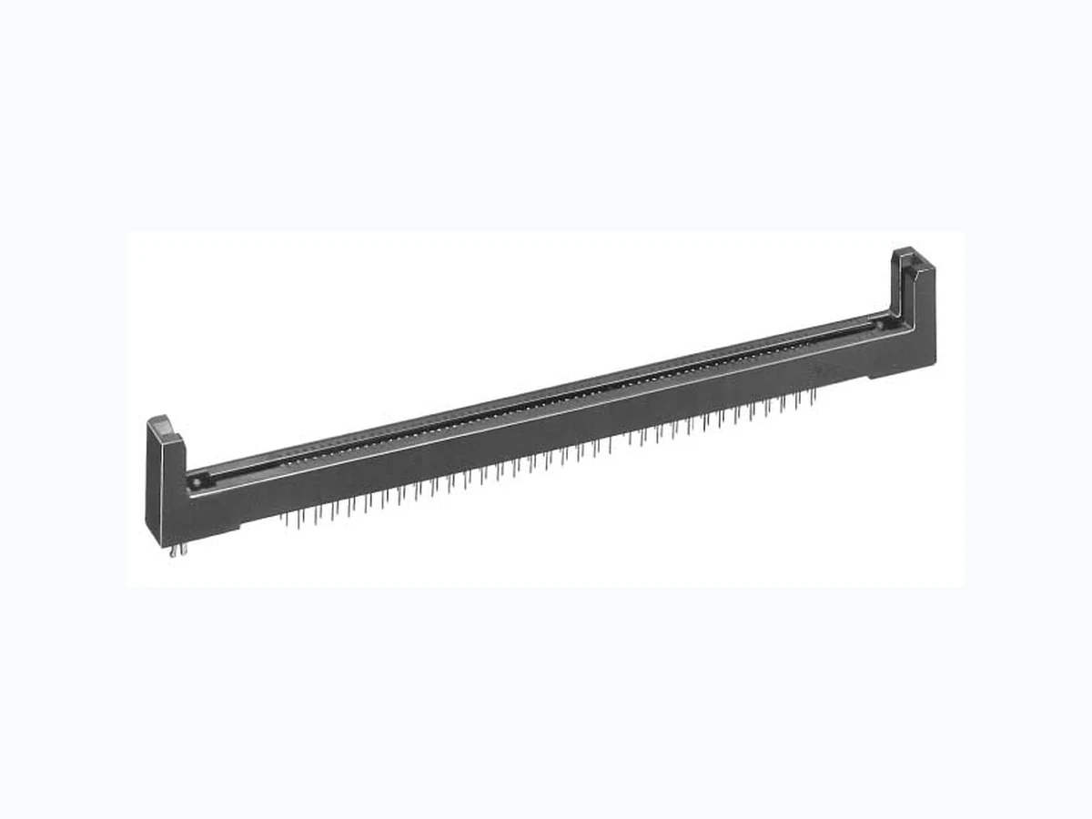
MCR89-130D-1.27DSA HIROSE
Document overview
- PDF pages: 4
Technical content
Page 1

IFeatures
1. High Reliability
This socket achieves high reliability in the horizontal contact spring system.
2. Low Insertion Force
This socket prevents mis-insertion force in the preload structure.
3. Easy Pattern Design
The dip contact through-hole diameter is only Ø0.5, and simplifies the pattern design.
IProduct Specifications
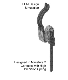
4. Miniature Type and High Density Mounting
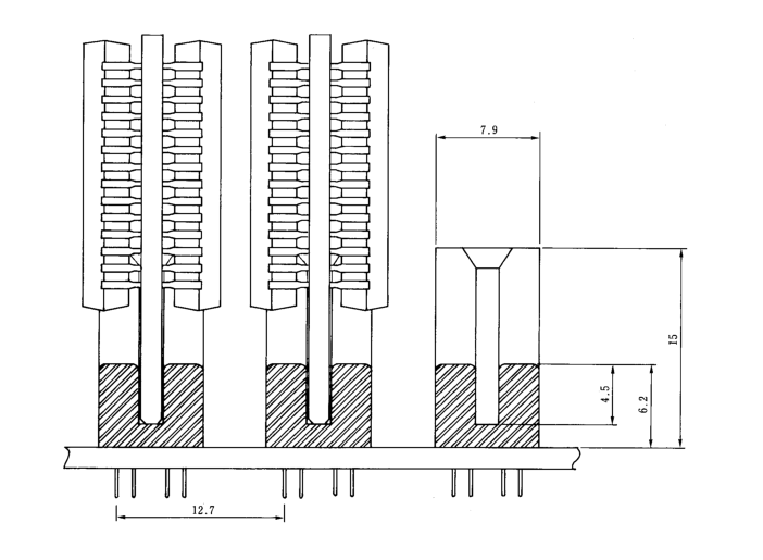
The low profile with 6.2mm height from the board is suitable for miniaturization of equipment. The 1.27mm pitch between contacts assures mounting with high density.
5. Wide Effective Mounting Area
This socket is capable of widening the effective mounting area on the module printed board, and secures retention function by easy locking.
6. Easy Board Mounting
The fixing pins are arranged in the same alignment as the contact, so as to easily install the connector in the board.
7. Accessories
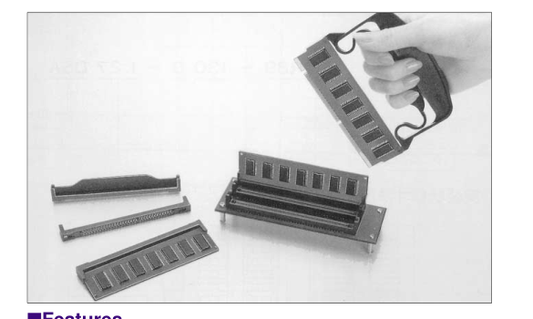
Dust covers and jigs to remove the board are available.
| Rating | Current rating: 0.5A | Operating Temperature Range: -30 to +85ç (Note 1) | Storage Temperature Range: -10 to +60ç (Note 2) |
| Voltage rating: 125V AC | Operating Humidity Range: 40 to 80% | Storage Temperature Range: 40 to 70% (Note 2) |
| Item | Specification | Conditions |
|---|---|---|
| 1. Contact Resistance | 1000M ohms min. | 500A DC |
| 2. Withstanding voltage | No flashover or insulation breakdown. | 500V DC / 1 minute |
| 3. Insulation Resistance | 20m ohms max. | 100mA |
| 4. Vibration | No electrical discontinuity of 10 µs or more | Frequency: 10 to 55 Hz, single amplitude of 0.75 mm, 2 hours in each of the 3 directions. |
| 5. Humidity (Steady state) | Insulation Resistance:1000M ohms min. | 96 hours at temperature of 40ç and humidity of 90% to 95% |
| 6. Temperature Cycle | No damage, cracks, or parts looseness. | 5 cycles under following condition; Temperature : -55: 30 minutes¡ +5 to 35ç: 5 minutes max.¡ 85ç : 30 minutes¡15- to 30ç 5 minutes max.) |
| 7. Durability (Insertion/withdrawal) | Contact resistance: 20m ohms max. | 200 cycles |
| 8. Resistance to Soldering heat | No deformation of components affecting performance. | Manual soldering: 300ç for 3 seconds |
Note 1: Includes temperature rise caused by current flow. Note 2: The term "storage" refers to products stored for long period of time prior to mounting and use. Operating Temperature Range and Humidity range covers non- conducting condition of installed connectors in storage, shipment or during transportation.
D2
Page 2
IMaterial
| Part | Material | Finish | Remarks | |
|---|---|---|---|---|
| Insulator | PPS | Color : Brown | UL94V-0 | |
| Contact | Beryllium copper | Contact area | Selective gold plating | --------------- |
| Lead area | Solder plating | |||
| Lock pin | Copper alloy | Solder plating | --------------- | |
IOrdering Information
MCR89 - 130 D - 1.27 DSA
1
2 3 4 5
| 1 Series Name: MCR89 | 5 Board installation type DSA: Straight dip type, board thickness 1.6mm DSC: Straight dip type, board thickness 2.6mm |
|---|---|
| 2 Number of Contacts: 130 | |
| 3 D: Double row | |
| 4 Contacts Pitch: 1.27mm |
BMounting Dimensions
D3
Page 3
IDip Straight Type
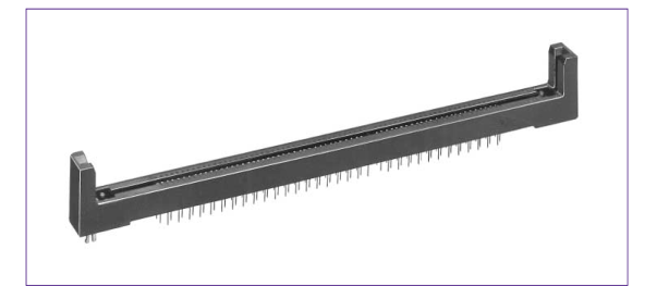
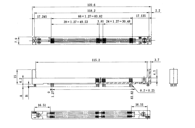
Unit: mm
| Part Number | CL No. | Number of Contacts | A | B |
|---|---|---|---|---|
| MCR89-130D-1.27DSA(01) | 548-0173-0-01 | 130 | 2.8 | 2.3 |
| MCR89-130D-1.27DSC(01) | 548-0185-9-01 | 3.8 | 3.4 |
Note: 25 pieces are packaged in one set for sale. The above table indicates a packaging of 25 pieces.
BPCB mounting pattern
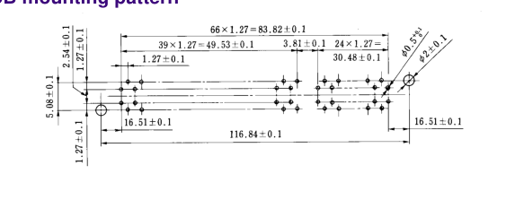
D4
Page 4
BRecommended Module Board Dimensions
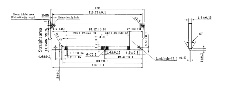
IDust Cover
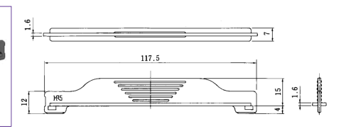
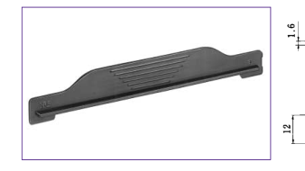
| Part Number | CL No. | Material | Finish |
|---|---|---|---|
| MCR89-130D-DC(01) | 548-0180-5-01 | ABS | Black |
Note: 100 pieces are packaged in one set for sale. The above table indicates a packaging of 100 pieces.
IModule Board Extraction Jig
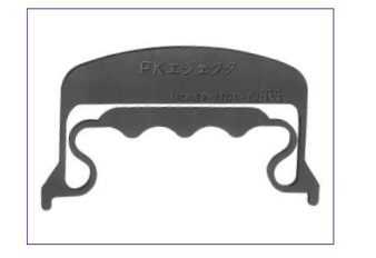
| Part Number | CL No. | Material | Finish |
|---|---|---|---|
| MCR89-130D-EJ | 548-0183-3 | Polyamid resin | Black |
Operating Instruction
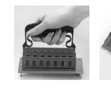
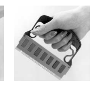
(1) Insert the jig protrusion
(2) By loosing force, the
in the board hole.
board is removed
Grasping the handle,
from the jig.
pull the board up.
D5