

 Download PDF
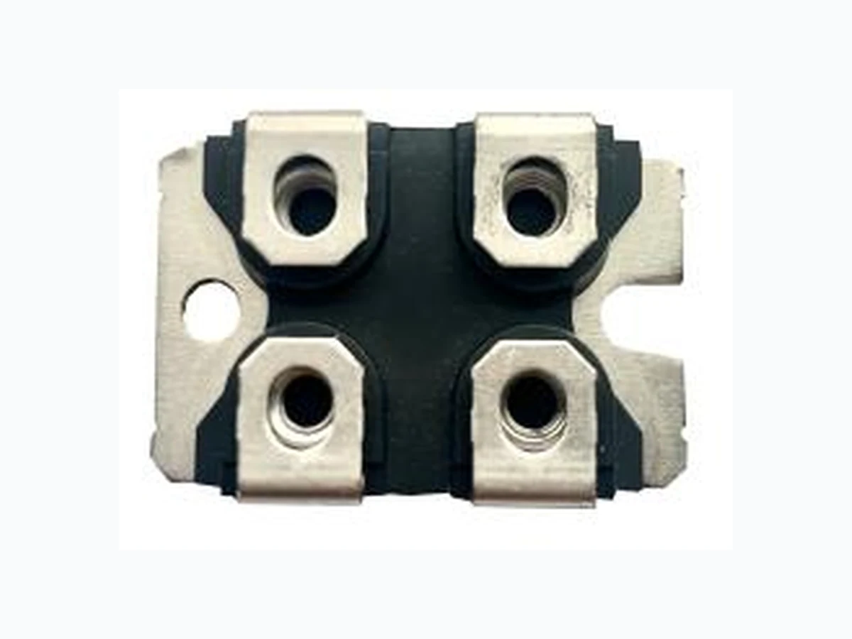
MCO100-12IO1 ISC
Document overview
- PDF pages: 3
Technical content
Page 1

Thyristor Module
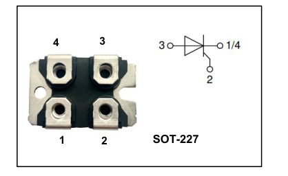
FEATURES
- Long-Term Stability
- Planar Passivated Chip
APPLICATIONS
- AC Power Control
- DC Motor Control
- Power Converter
ABSOLUTE MAXIMUM RATINGS(Ta=25℃)
| SYMBOL | PARAMETER | VALUE | UNIT | |
|---|---|---|---|---|
| V DRM | Repetitive Peak Off-state Voltage | 1200 | V | |
| V RRM | Repetitive Peak Reverse Voltage | 1200 | V | |
| I T(AV) | On-state current | Tc= 80℃, T= 150℃ J | 101 | A |
| I RMS | RMS forward current, 180°sine | 160 | A | |
| I TSM | Non-repetitive Peak On-state Current t=10ms, 50Hz, sine, T= 45℃ J | 1.40 | kA | |
| Non-repetitive Peak On-state Current t=8.3ms, 60Hz, sine, T= 45℃ J | 1.51 | kA | ||
| I2t | I2t Value for Fusing t=10ms, 50Hz, sine, T= 45℃ J | 9.8 | kA2s | |
| I2t Value for Fusing t=8.3ms, 60Hz, sine, T= 45℃ J | 9.49 | kA2s | ||
| di/dt (cr) | Critical rate of rise of on-state current, T= 150℃ J | 150 | A/us | |
| dv/dt (cr) | Critical rate of rise of off-state voltage, T= 150℃ J | 1000 | V/us | |
| T J | Virtual Junction Temperature | -40 ~150 | ℃ | |
| T stg | Storage Temperature | -40 ~125 | ℃ | |
| V ISOL | Isolation Voltage 50/60Hz, sinusoidal, t=1min | 2500 | V | |
Page 2

Thyristor Module
ELECTRICAL CHARACTERISTICS (TC=25℃ unless otherwise specified)
| SYMBOL | PARAMETER | CONDITIONS | MIN | TYP. | MAX | UNIT |
|---|---|---|---|---|---|---|
| V T | On-State Voltage | I = 100A, T= 25℃ T J | -- | -- | 1.31 | V |
| On-State Voltage | I = 200A, T= 25℃ T J | 1.66 | V | |||
| V TO | Threshold Voltage For Power-loss Calculations Only, T= 150℃ J | -- | -- | 0.85 | V | |
| r T | Slope Resistance For Power-loss Calculations Only, T= 150℃ J | -- | -- | 4.5 | mΩ | |
| I GT | Gate-Trigger Current | V = 6V, T= 25℃ D J | -- | -- | 100 | mA |
| V GT | Gate-Trigger Voltage | V = 6V, T= 25℃ D J | -- | -- | 1.5 | V |
| I L | Latching Current | T= 25℃ J | -- | -- | 450 | mA |
| I H | Holding Current | V = 6V, T= 25℃ D J | -- | -- | 200 | mA |
| R th j-c | thermal resistance junction to case for Thyristor | -- | -- | 0.35 | ℃/W | |
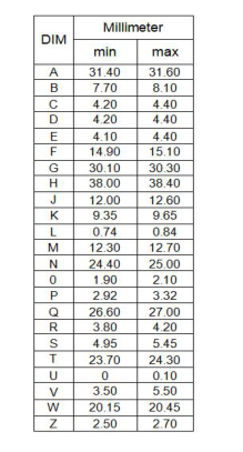
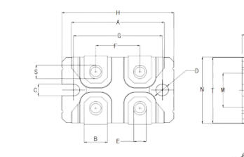
PACKAGE OUTLINE(UNIT:mm)
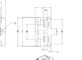
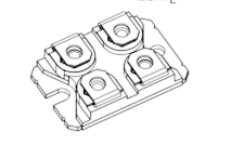
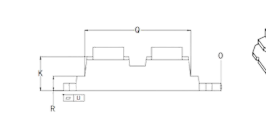
Page 3

Thyristor Module
PRODUCT DISCLAIMER
ISC reserves the rights to make changes of the content herein the datasheet at any time without notification. The information contained herein is presented only as a guide for the applications of our products.
ISC products are intended for usage in general electronic equipment. The products are not designed for use in equipment which require specialized quality and/or reliability, or in equipment which could have applications in hazardous environments, aerospace industry, or medical field. Please contact us if you intend our products to be used in these special applications.
ISC makes no warranty or guarantee regarding the suitability of its products for any particular purpose, nor does ISC assume any liability arising from the application or use of any products, and specifically disclaims any and all liability, including without limitation special, consequential or incidental damages.
It is strictly prohibited to reprint or copy part or all of this datasheet without permission from ISC.