
 Download PDF
MBU120 MPSIND
Document overview
- PDF pages: 2
Technical content
Page 1
MBU120 SERIES
120W Open Frame Switching Power Supplies For Medical Equipment. Description:
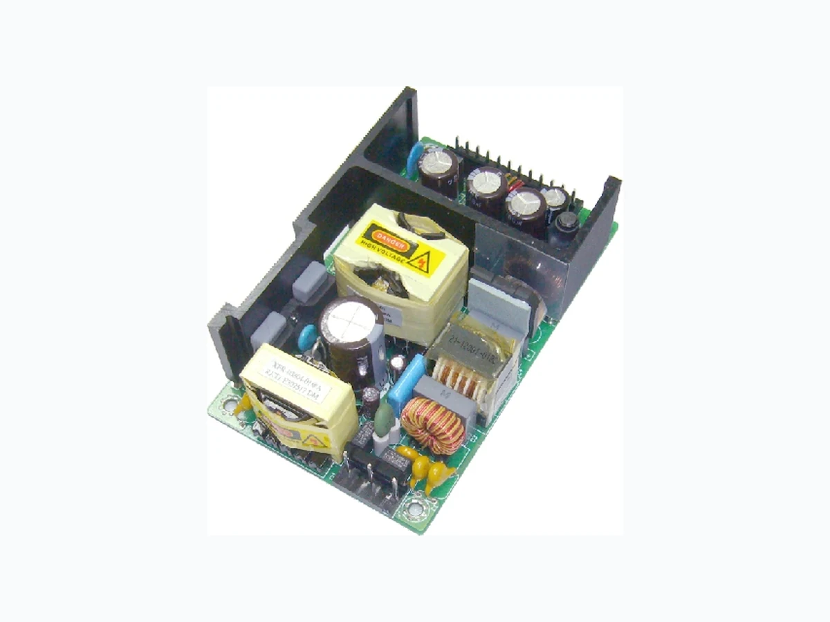
The MBU120 series of compact, open frame constructed, AC/DC switching mode power supplies provide 120 Watts of continuous output power.They are suited for use in hospital instrument and many other applications. All models meet FCC Part-18 class B and CISPR-11 EN55011 class B emission Limits and are designed to comply with
nd
nd
UL/c-UL(UL 60601-1:2 Edition) ,TUV/T-mark(EN 60601-1:2 Edition) and new CE requirements. All units are 100% burned in and tested.
Features:
Wide Operating Voltage 90 to 260 VAC,47 to 63 Hz Internal EMI filter Single Output Input connector mates with Molex housing 09-50-3051 and Molex 2478 series crimp terminal Output Connector mates with screw terminal (Terminal Block)(16-22AWG) or Molex housing 09-50-3121 and Molex 2478 series crimp terminal Input Surge Current, Over Voltage and Over Load protection Output Voltage Protection(Crowbar Design) Active Power Factor Correction
Safety Approvals :
Size: 3"x5"x1.42” Class I
EN 60601-1
3 year warranty
IEC 60601-1
Electrical Characteristics:
| Sym. | Parameter | Test Conditions | Min. | T y p . | M ax | . Unit |
|---|---|---|---|---|---|---|
| Vin | Safety Approvals Input Voltage Range | 100 | 240 | V A C | ||
| Operate Voltage Range | 90 | 260 | V A C | |||
| fin | Input Frequency | 47 | 63 | H z | ||
| PF | Power Factor Correction | Io=Full load, Vin=90~260VAC | 0.95 | 0.97 | 1.0 | |
| Po | Output Power Range | Vin=90 to 260 VAC | 0 | 1 2 0 | W | |
| Vo | Output Voltage Range | See rating Chart | V | |||
| Io | Output Current Range | See rating Chart | A | |||
| Iil | I n p ut Current (Low Line) | Io=Full load, Vin=115VAC | 1.7 | A | ||
| Iih | I n p ut Current (High Line) | Io=Full load, Vin=230VAC | 0.8 | A | ||
| I rl | L o w Line Inrush Current | Io=Full load, 25 C,Cool start, Vin=115VAC | 48 | 5 4 | A | |
| I rh | H i g h Line Inrush Current | Io=Full load, 25 C,Cool start, Vin=230VAC | 58 | 63 | A | |
| Eff | E f f iciency | I o = F u ll l o a d , V i n = 2 3 0 VAC | 70 | 80 | 88 | % |
| REG-i | Line Regulation | Io=Full load | 0.5 | 1 | % | |
| REG -o | Load Regulation | Vin=230VAC | 3 | 5 | % | |
| OVP | O ver Voltage Protection | 112 | 132 | % | ||
| OCP | Over Current Protection | 110 | 150 | % | ||
| Ttr | T i me of Transient Response | I o = F ull load to Half Load, Vin=100VAC | 4 | mS | ||
| Thold | Hold-Up Time | Io=Full load, Vin=110VAC | 16 | mS | ||
| Ts | S ta rt Up Time | Io=Full load, Vin=100VAC | 0.3 | 1 | 2 | S |
| Vp-p | Ripple & Noise (Peak to Peak) | Full load, Vin=90VAC | 0.5 | 1 | % | |
| Ilk | S a f ety Ground Leakage Current | Io=Full load, Vin=240VAC | 0.095 | 0.1 | mA | |
| TC | Temperature Coefficient | All output | -0.04 | 0.04 | %/ C | |
Environmental :
| Sym. | Parameter | Test Conditions | Min. | T y p . | M ax. | Unit |
|---|---|---|---|---|---|---|
| Toper | Operating Temperature | 0 | 5 0 | 7 0 | C | |
| Tstg | S torage Temperature | -40 | 8 5 | C | ||
| Ho | O p e rating Humidity | 0 | 9 5 | % | ||
| Hr | S t o rage Humidity | 0 | 7 5 | % | ||
| MTBF | Operating Temperature at 25 C, Calculated per MIL-HDBK-217F | 0.1M | H r s | |||
| Pd | D e rate linearly from 100% load at 50 C to 50% load at 70 C | |||||
C C
Hrs
Page 2
MBU120 SERIES
120W Open Frame Switching Power Supplies For Medical Equipment.
Safety Specifications:
| Sym. Parameter | Test Conditions | Min. | T y p . | M ax | . Unit |
|---|---|---|---|---|---|
| Dielectric Withstanding Vol Vps for Primary to secondary | tage Primary to secondary | 5656 | VDC | ||
| Dielectric Withstanding Vol Vpg for Primary to Ground | tage Primary to ground | 2828 | VDC | ||
| Ris P o w e r Factor Corrention | Test Voltage=500VDC | 50 | M | ||
| ISPR Output Power Range | V i n=220VAC | B | C L A S S | ||
| FCC O utput Voltage Range | Vin=110VAC | B | C L A S S |
B
Output Voltage And Current Rating Chart (Single Output) :
| Model Number Output Voltag | e Output Current | Total Regulation | Maximum Output Power |
|---|---|---|---|
| MBU120-102 5~6 VDC | 20.00~16.66 A | 7% | 100W |
| MBU120-103 6~9 VDC | 18.33~12.22 A | 7% | 110W |
| MBU120-104 9~11 VDC | 13.33~10.90 A | 5% | 120W |
| MBU120-105 11~13 VDC | 10.90~9.23 A | 5% | 120W |
| MBU120-106 13~16 VDC | 9.23~7.50 A | 5% | 120W |
| MBU120-107 16~21 VDC | 7.50~5.71 A | 3% | 120W |
| MBU120-108 21~27 VDC | 5.71~4.44 A | 3% | 120W |
| MBU120-109 27~33 VDC | 4.44~3.63 A | 2% | 120W |
| MBU120-110 33~40 VDC | 3.63~3.00 A | 2% | 120W |
PIN CHART
PIN
3 5 6 8 9 10
1 2 4 7
11 12
MODEL
MBU120-1XX-12PIN OUT OUT OUT OUT OUT OUT RTN RTN RTN RTN RTN
RTN
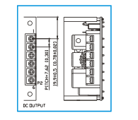
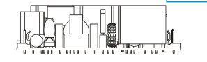
Mechanical Specifications :
| PIN MODEL | 1 | 2 | 3 | 4 | 5 | 6 |
| MBU120-1XX-6PIN | OUT | OUT | OUT | RTN | RTN | RTN |
Note: 1. Dimensions are shown in inches or mm. 2. Weight: 365gs approx.
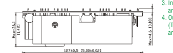
- Input connector mates with Molex housing 09-50-3051 and Molex 2478 series crimp terminal. 4. Output connector mates with screw terminal (Terminal Block)(16-22AWG)or Molex housing 09-50-3121 and Molex 2478 series crimp terminal
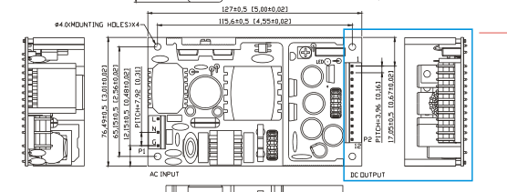
(Optional)