
 Download PDF
MBE1000 BEL
Document overview
- PDF pages: 8
Technical content
Page 1

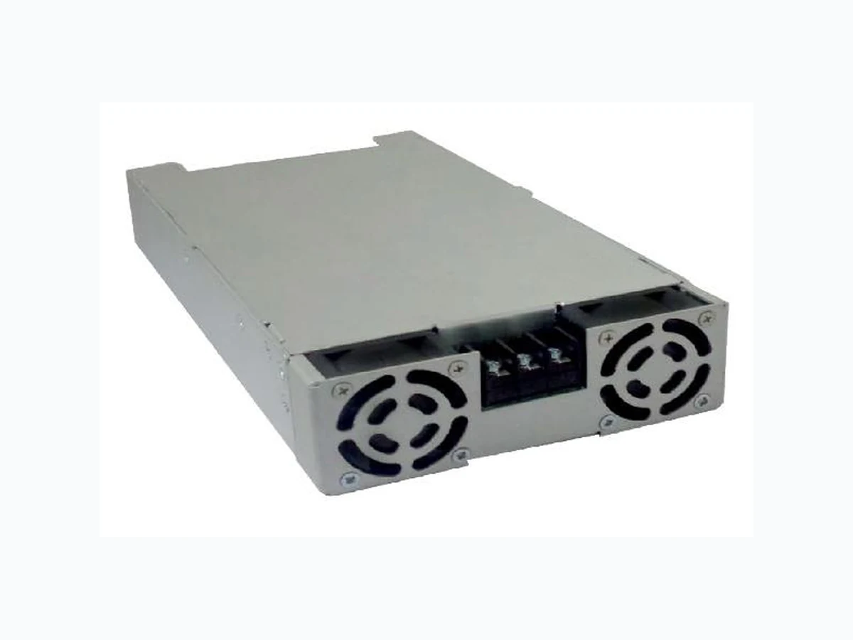
The MBE1000 Series medical power supplies, with its wide universal 85 - 264 VAC input range, is available at 1000 W of output power and a variety of single output voltages.
The MBE series is designed and approved to the latest Medical standards (EN/IEC 60601-1), providing 2 x MOPP isolation for Class I & Class II applications.
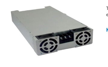
These medical power supplies are ideal for monitoring, home health equipment as well as surgical devices.
- Form Factor 5 x 9.51 x 1.61 in (127 x 241.5 x 41 mm)
- Approved to EN 60601
- Dual Fusing
- Current Sharing Option
- Peak Power Capability
- Standard IEC 60601-1-2: 2014 (4th Edition)
- 5 VDC Stand by output
- In built 12 V fan output
- Power Good / Power Fail Signal
- Suitable for BF application
- Lesser than 1U high
- High voltage output range up to 58 VDC
- N+1 redundant power supply
- Single wire current sharing
- Built in OR-ing diode / FET (- R suffix
- Diagnostic
- Home Health Care
- Drug Pump
- Monitoring
- Dialysis
- Imaging
- Hospital Beds
- Therapy Devices

Page 2
2
MBE1000-1T12
12 V
Fan Cooled
41.67 A
0.0 A
2%
MBE1000-1T15
15 V
Fan Cooled
41.67 A
0.0 A
2%
MBE1000-1T24
24 V
Fan Cooled
41.67 A
0.0 A
2%
MBE1000-1T30
30 V
Fan Cooled
33.33 A
0.0 A
2%
MBE1000-1T48
48 V
Fan Cooled
20.83 A
0.0 A
2%
MBE1000-1T58
58 V
Fan Cooled
17.24 A
0.0 A
2%
1 For Ripple measurement minimum output power requirement is 25 W. Ripple is peak to peak with 20 MHz bandwidth and 10 µF (Electrolytic capacitor) in parallel with a 0.1 µF capacitor at rated line voltage and load ranges.
Specifications are for nominal input voltage, 25°C unless otherwise stated.
Input Voltage
Universal
Input Frequency
120 VAC:
Input Current
240 VAC:
Input Protection
In Live & Neutral both
85 – 264 VAC / 120 – 390 VDC
47 – 63 Hz 11 A max. 5.5 A max. F16 A / 250 V
Over entire input range with main output kept OFF using
No Load Power
Remote ON/OFF
Inrush Current
240 VAC:
Leakage Current
240 VAC / 50 Hz
Touch Current:
120 VAC:
Power Factor
240 VAC: PFC converter: Variable
Switching Frequency
Resonant converter: Variable

3 W typ.
25 A max.
400 µA
< 100 µA 0.98 0.95 85 kHz typical 100 kHz typical
Page 3
Output Voltage
Refer to Model Selection table for details
Standby Output Voltage 2 Output Power 3
Fan Cooled (Peak 1200 W for 1 ms) 120 VAC:
Efficiency
240 VAC:
Hold-up Time
120 VAC / 240 VAC:
Line Regulation Load Regulation
Transient Response
50% to 100% load change, 50 Hz, 50% duty cycle, 0.1 A/µs
Voltage Adjustment Set Point Tolerance Rise Time Over Current Protection
Hic-Up Type, autorecovery
Over Voltage Protection
Latch Type, AC Power to be recycled for recovery
Short Circuit Protection
Short term, autorecovery
Over Temperature Protection
Autorecovery
Current Share
Up to 3 supplies connected in parallel (optional)
Cooling
Fan cooled
2
3
12 V to 58 V 5 V 1000 W 88 % Typical 93 % 8 ms ± 0.5 % ± 1.0 % < 10 %, recovery time < 5 ms ± 3 % ± 1% <100 ms 120 to 150 % 114%
130-140°C primary heat sink
1000 W
Standby output voltage 5 V / 1.5 A with tolerance including set point accuracy, line and load regulation is +/-10%. Ripple and noise is less than 5%. 3 Combined output power of main output, fan supply and standby supply shall not exceed max. power rating.
Conducted Emissions
EN 55011-B, CISPR22-B, FCC PART15-B
Class B
EN 55011
Class A
Radiated Emissions
With External king core K5B RC 25x12x15-M or equivalent
Class B
Input Current Harmonics
EN 61000-3-2
Class A
Voltage Fluctuation and Flicker
EN 61000-3-3
Complies
ESD Immunity
EN 61000-4-2
A
Radiated Field Immunity
EN 61000-4-3
A
Electrical Fast Transient Immunity EN 61000-4-4
A
Surge Immunity
EN 61000-4-5
A
Conducted Immunity
EN 61000-4-6
A
Magnetic Field Immunity
EN 61000-4-8
A
Voltage Dips, Interruptions
EN 61000-4-11
A & B

Asia-Pacific Europe, Middle East
North America
+86 755 298 85888
+353 61 225 977
+1 408 785 5200
© 2020 Bel Power Solutions & Protection
BCD.00973_D
Page 4
4
Input to Output
4245 VAC
Isolation Voltage
Input to Earth
1625 VAC
Output to Earth
1500 VAC
EN 60601-1, IEC 60601-1 (ed.3), ANSI/AAMI ES 60601-1,
Safety Standard(s)
CSA C22.2 No. 60601-1
Agency Approvals
Nemko, UL, C-UL
CE mark
Complies with LVD Directive
Operating Temperature
Refer to derating curve
-40 to +70°C
Storage Temperature
-40 to +85°C
Relative Humidity
Non-condensing
5% to 95%
Operating:
16,000 ft.
Altitude
Non-operating:
40,000 ft.
MTBF
Telcordia -SR332-issue 3
3.37 million hours
Power Good: Is a TTL signal which goes high after main output reaches 90% of its set value.
Power Good / Fail Signal
The delay is 0.1 s to 0.5 s Power Fail: The same signal goes low at least 1ms before main output falls to 90% of set value at AC Power off
Remote Sense
Compensates for 200 mV drop Pin 6 & Pin 7 of J3 can be used for Remote on/off. Shorting Pin 6 to Pin 7 enables main output while keeping the pins open disables main output
Remote On / Off
Note: Provision of Inhibit Remote ON/OFF is available. +5 V at Pin 7 will switch off the main output.
OCP Limit Set
Pin 8 & Pin 9 of J3 must be shorted
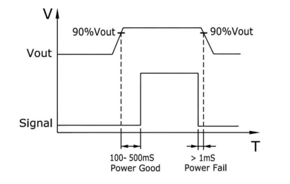
Figure 1. Power Good / Fail Signal Diagram

Page 5
5
Pin 1 AC Line
AC Input Connector
J1 Pin 2 Neutral
TE Connectivity: NC6-P107-03
Pin 3 Earth

Pin 2 5V AUX Pin 3 PGPF Pin 4 VS – Pin 5 VS +
Molex: 22-23-2101
J3 4
Signal Connector
Pin 6 GND
Mating: 22-01-2107; Pins: 08-50-0113
Pin 7 RMT Pin 8 CL2 Pin 9 CL1 Pin 10 LS
TE Connectivity AMP Connectors Description: CONN HEADER VERT 2 POS 2.54 mm,
Pin 1 +VE
Fan Output 5
J10, J11
MPN: 640456-2
Pin 2 -VE
Mating: 3-641535-2 / TE Connectivity AMP Connectors or: 0022013027 / MOLEX with crimping 08-50-0114 / MOLEX
4 PSU is supplied with J3, pin-6 and pin-7 shorted to enable main output without remote on/off feature. 5 Fan supply output voltage is 12 V / 500 mA with regulation band ± 30 % and Ripple is less than 10%. To get 12 V Fan supply output voltage, minimum 10 % load on Main output voltage is required.

North America
Asia-Pacific Europe, Middle East +86 755 298 85888
+353 61 225 977
+1 408 785 5200
© 2020 Bel Power Solutions & Protection
BCD.00973_D
Page 6
6
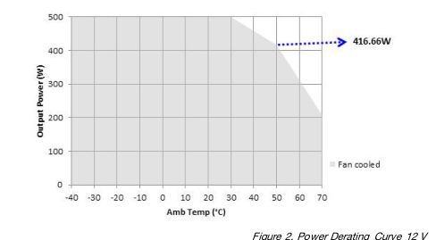
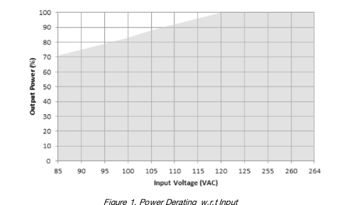
De-rate between 30-50 °C @ 0.833% per °C De-rate above 50 °C @ 2.5% per °C
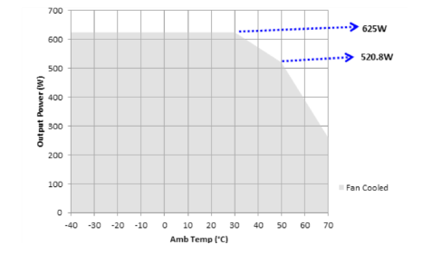
De-rate between 30-50 °C @ 0.833% per °C De-rate above 50 °C @ 2.5% per °C
Figure 3. Power Derating Curve 15 V
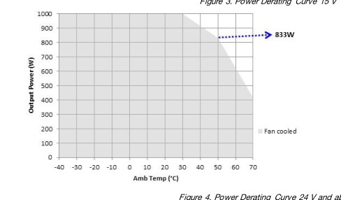
De-rate between 30-50 °C @ 0.833% per °C De-rate above 50 °C @ 2.5% per °C
Figure 4. Power Derating Curve 24 V and above

Page 7
7
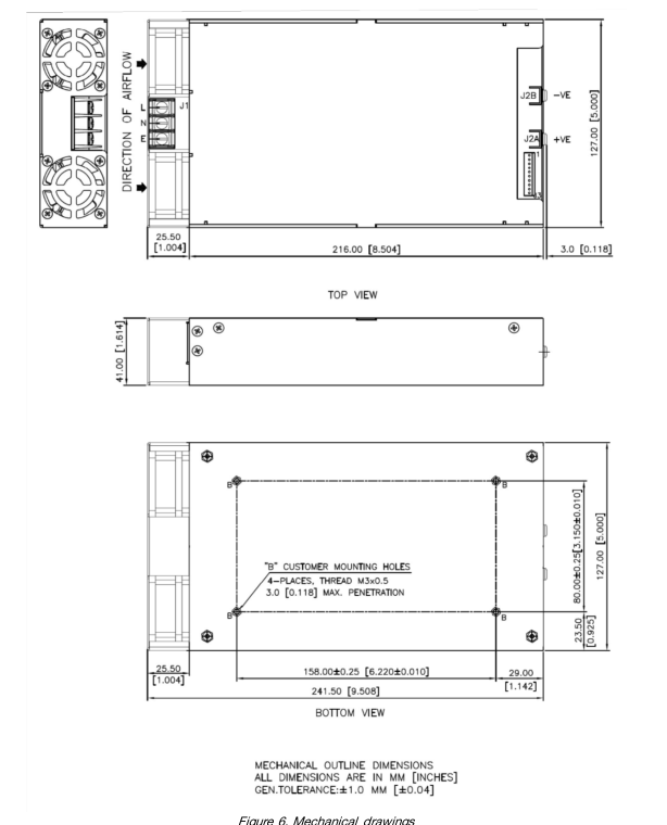
Weight
1300 g
127 x 241.5 x 41 mm (5 x 9.51 x 1.61 inches)
Dimensions

North America
Asia-Pacific Europe, Middle East +86 755 298 85888
+353 61 225 977
+1 408 785 5200
© 2020 Bel Power Solutions & Protection
BCD.00973_D
Page 8
8
During the installation and setup of parallel supplies in a system it is important that a single remote sense point be used for all the supplies. The remote sense voltage between the supplies must be adjusted to within 1% to ensure the supplies are inside the 1% capture window. If the supplies are not initially adjusted inside the capture window the supplies will not current share satisfactorily.
SET-UP PROCEDURE:
- Connect load cables to the outputs of each supply. 2. Connect the remote sense lines to the load in twisted style. (A common remote sense point must be used for all the supplies in parallel). 3. Connect all the “LS” signal (Pin 10) on the J3 connector between the supplies. 4. Adjust remote sense voltage of each supply to within 1% of rated output voltage or readjust to required set point. (Adjustment to be done with all other parallel supplies off). 5. Current sharing between the supplies can be verified by monitoring the output current of each supply with a hall effect DC current probe. The supplies should share to within 10% of the total load current.
- The current share circuit has a capture window voltage of +/- 1% of the rated output voltage. If the output remote sense voltage of one of the supplies is adjusted outside the 1% window the supplies will not current share satisfactorily.
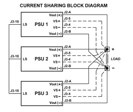
Figure 7. Current Sharing Block Diagram
NUCLEAR AND MEDICAL APPLICATIONS - Products are not designed or intended for use as critical components in life support systems, equipment used in hazardous environments, or nuclear control systems. TECHNICAL REVISIONS - The appearance of products, including safety agency certifications pictured on labels, may change depending on the date manufactured. Specifications are subject to change without notice.