
 Download PDF
MBC150 BEL
Document overview
- PDF pages: 6
Technical content
Page 1

The MBC150 Series of open-frame medical power supplies, with its wide universal input range 90-264 VAC, is available at 150 W of output power with forced-air cooling and a variety of single output voltages.
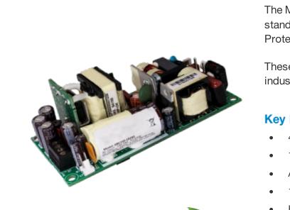
The MBC series is designed and approved to the latest Medical standards (EN/IEC 60601-1), providing 2 x MOPP (Means of Patient Protection) isolation for Class I & Class II applications.
These power supplies are ideal for medical, telecom, datacom, industrial equipment and other applications.
4 x 2 x 1.3 Inch Form Factor
150 W with Forced-Air Cooling
Approved to EN/IEC 60601-1
12 V @ 0.5 A fan voltage auxiliary output
- High Efficiency > 86%
- Low conducted and radiated noise
- Light weight
- IEC Protection Class Options: − Class I: Earthing Tab J4 (no suffix) − Class II: No Earthing Tab (-2 suffix)
- Medical Safety Agency Approvals
- RoHS Compliant
- Diagnostic
- Dialysis
- Drug Pump
- Home Health Care
- Monitoring
- Portable Equipment

Page 2
2
MAX LOAD 2
OUTPUT
MODEL 1
CONNECTOR
MIN LOAD
POWER
VOLTAGE
CONVECTION
300 LFM
MBC150-1005G
JST (Header)
16.0 A
80 W
5 VDC
16.0 A
0.0 A
MBC150-1T05G
Screw Terminal
20.0 A
100 W
MBC150-1012G
JST (Header)
0.0 A
12 VDC
8.33 A
12.5 A
150 W
MBC150-1T12G
Screw Terminal
MBC150-1015G
JST (Header)
15 VDC
6.67 A
10.0 A
0.0 A
150 W
MBC150-1T15G
Screw Terminal
MBC150-1024G
JST (Header)
24 VDC
4.17 A
6.25 A
0.0 A
150 W
MBC150-1T24G
Screw Terminal
MBC150-1048G
JST (Header)
0.0 A
48 VDC
2.08 A
3.13 A
150 W
MBC150-1T48G
Screw Terminal
COVER-150-XBC 3 Metal Cover Kit (accessory)
1 Class I products have an Earthing tab. For Class II version (without Earthing tab) add suffix -2 (e.g.: MBC150-1012G-2). 2 Combined output power from V1 and VFAN should not exceed the total output power rating. 3 When used in Cover Kit, de-rate output power to 70 % under all operating conditions.
Specifications are for nominal input voltage, 25°C unless otherwise stated.
PARAMETER
DESCRIPTION / CONDITION
Input Voltage
Universal
Input Frequency
120 VAC:
Input Current
230 VAC:
No Load Power
120 VAC:
Inrush Current
230 VAC: 120 VAC:
Leakage Current
230 VAC:
No Load Power
PFC converter (variable)
Switching Frequency
Resonant converter (variable)

SPECIFICATION
90 – 264 VAC / 120 – 390 VDC
47 – 63 Hz 1.70 A max. 0.85 A max. 1.2 W 35 A max. 65 A max. < 140 µA < 250 µA 1.2 W 35 – 250 kHz, 90 kHz typical 35 – 250 kHz, 90 kHz typical
Page 3
PARAMETER
DESCRIPTION / CONDITION
Output Voltage
Refer to Model Selection table
Output Power 4
Peak Power: 170 W for 2 s
Fan Output 5
@ 5 A 120 VAC:
Efficiency
230 VAC: 120 VAC:
Hold Up Time
230 VAC: 120 VAC:
Power Factor
230 VAC:
Line Regulation
Load Regulation
Transient Response
50 to 100% load change, 50 Hz, 50% duty cycle, 0.1A / µs
Ripple 6
All outputs
Rise Time
Set Point Accuracy
Main output
Output Voltage Adjustment
V1
Over Current Protection
Over Voltage Protection
V1
Short Circuit Protection
Short term, Automatic recovery
Convection
Cooling
300 LFM
4 Derate output power linearly to 80% from 90 VAC to 80 VAC input. 5 Fan output voltage tolerance is +/-20 %. Peak current for fan output is 1 A.
3
SPECIFICATION
5 V to 48 V
150 W
12 V 84% typical 86% typical 6 ms 10 ms 0.99 0.95 ± 0.5%
± 2.0% < 10%, recovery time < 5 ms 1.0 % max
< 100 ms
± 1%
± 3 %
110% typical above rating
110 to 150%
80 W (5 V model), 100 W (other models)
100 W (5 V model), 150 W (other models)
6 Ripple is 2 % up to 20 % load and < 1 % above 20 % load. Ripple is peak to peak with 20 MHz bandwidth and 10 µF (Electrolytic capacitor) in parallel with a 0.1 µF capacitor at rated line voltage and load ranges.
Conducted Emissions
EN 55011-B, CISPR22-B, FCC PART15-B
Radiated Emissions
EN 55011 B
Input Current Harmonics
EN 61000-3-2
Voltage Fluctuation and Flicker
EN 61000-3-3
ESD Immunity
EN 61000-4-2
Radiated Field Immunity
EN 61000-4-3
Electrical Fast Transient Immunity
EN 61000-4-4
Surge Immunity
EN 61000-4-5
Conducted Immunity
EN 61000-4-6
Magnetic Field Immunity
EN 61000-4-8
Voltage Dips, Interruptions
EN 61000-4-11

Pass
Pass
Class D
Pass
Level 4, Criterion A
Level 3, Criterion A
Level 3, Criterion A
Level 3, Criterion A
Level 3, Criterion A
Level 4, Criterion A
Criterion A & B
Asia-Pacific Europe, Middle East
North America
+86 755 298 85888
+353 61 225 977
+1 408 785 5200
© 2021 Bel Power Solutions & Protection
BCD.00288_AF
Page 4
4

Agency Approvals
Nemko, UL, C-UL
CE mark
Complies with LVD Directive
PARAMETER
DESCRIPTION / CONDITION
Operating Temperature 7
-20 to 0°C start-up is guaranteed
Storage Temperature
Humidity
Non Condensing Operating:
Altitude
Non-Operating:
Reliability
MTBF according to Telcordia -SR332-Issue 3
7 Refer to derating curves
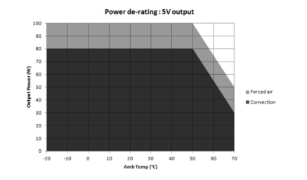
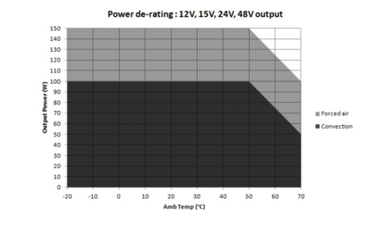
Figure 1. Derating Curves

SPECIFICATION
-20 to 70°C
-40 to 70° C
95% 10,000 ft. 40,000 ft. 2.4 million hours
Convection load: 80 W up to 50 °C De-rate above 50 °C @ 3.125% per °C
Forced air cooled load: 100W up to 50°C De-rate above 50 °C @ 2.5% per °C
Convection load: 100 W up to 50 °C De-rate above 50 °C @ 2.5% per °C
Forced air cooled load : 150 W up to 50°C De-rate above 50 °C @ 1.67% per °C
Page 5
5
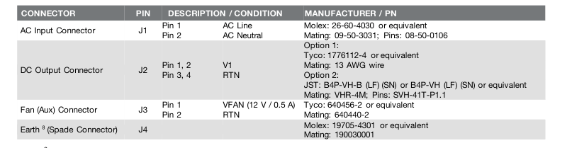
8 Class I product only
PARAMETER
DESCRIPTION / CONDITION
Weight
150 g (0.33 lbs.)
Dimensions
101.6 x 50.8 x 33.6 mm (4.0 x 2.0 x 1.3 inch)
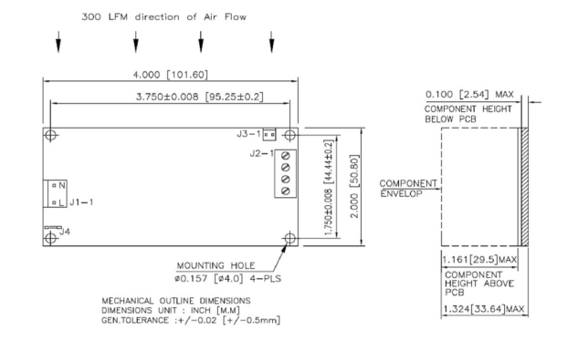
Figure 2. Mechanical Drawing
NOTES: In case the PCB is mounted in a metal enclosure, using metal hardware ensure the following: 1 Stand off, used to mount PCB has OD of 5.4 mm max. 2 Screws, used to fix PCB on stand off, have head dia of 6.0 mm max. 3 Washer, if used, to have dia of 6.5 mm max.

North America
Asia-Pacific Europe, Middle East +86 755 298 85888
+353 61 225 977
+1 408 785 5200
© 2021 Bel Power Solutions & Protection
BCD.00288_AF
Page 6
6
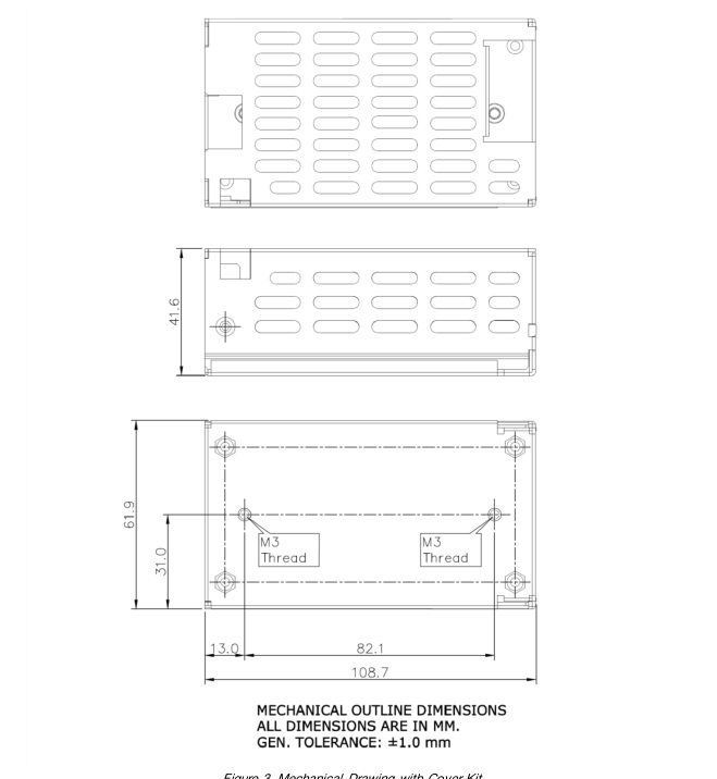
Figure 3. Mechanical Drawing with Cover Kit
NUCLEAR AND MEDICAL APPLICATIONS - Products are not designed or intended for use as critical components in life support systems, equipment used in hazardous environments, or nuclear control systems. TECHNICAL REVISIONS - The appearance of products, including safety agency certifications pictured on labels, may change depending on the date manufactured. Specifications are subject to change without notice.