
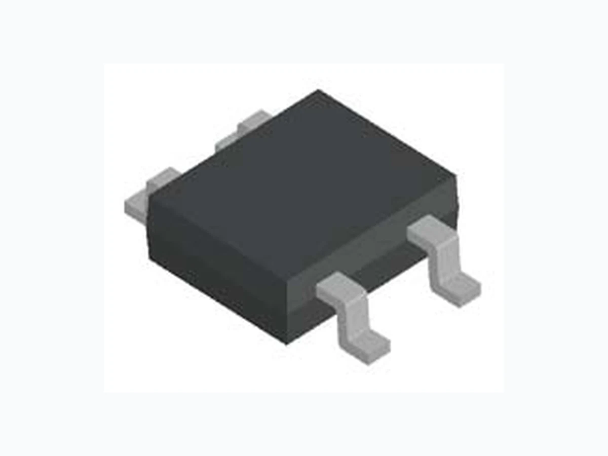
MB05F-S LEIDITECH
Document overview
- Manufacturer or author: Provided By www.digicamel.com(FREE DATASHEET DOWNLOAD SITE)
- PDF pages: 3
Technical content
Features
Glass passivated die construction Low forward voltage drop High surge current capability Desgned for surface mount application Component in accordance to RoHS 2011/65/EU Major Ratings and Characteristics Mechanical Date Case:MBF-S Molding compound meets UL 94 V-0 flammability rating Terminals: Solder plated, solderable per MIL-STD-750, Method 2026 Polarity: Polarity symbols marked on body Marking: type number Maximum Ratings & Thermal Characteristics A = 25 °C unless otherwise noted) I F(AV) 0.5A,0.8A V RRM 50V to 1000V I FSM 30A Items Maximum repetitive peak reverse voltage Maximum RMS reverse voltage Maximum DC blocking voltage Maximum average forward rectified current at T A (see Fig1.) -on glass-epoxy P.C.B (1) -on aluminum substrate (2) I F(AV) 0.8 Peak forward surge current 8.3ms single half sine-wave superimposed on rated load Thermal resistance from junction to ambient 0.5 T T STG -55 to +150 R θJL (1) 140 280 420 600 V560 °C/W Symbol MB 10F-S V 80050 100 200 400 600V RRM MB 05F-S MB 1F-S A 400 A 700 800 1000 1.0V 5.0μA V T j max. 150℃ 1000 UnitMB 2F-S MB 4F-S MB 6F-S MB 8F-S I R V F R θJA (1) 100 35 70 200 V RMS V DC I FSM Thermal resistance from junction to lead Operating junction and storage temperature range MBF-S Rev : 01.06.2014 1/3 www.leiditech.com
Electrical Characteristics
A = 25 °C unless otherwise noted) Characteristic Curves A =25 ℃ unless otherwise noted) T A =25°C T A =125°C - - - Test conditions I F =0.5A 5.0 500 Symbol V F I R V Type Max 1.0 Min μA UnitItems Forward voltage per element Peak reverse current at rated DC blocking voltage 1 10 100 Peak Forward Surge Current (A) Number of Cycles at 60 Hz Fig.2 Maximum Peak Forward Surge Current(per leg) 0.01 0.1 0.2 Instantaneous Forward Current (A) Instantaneous Forward Voltage (V) Fig.3 Typical Forward Characteristics(per leg) 0.01 0.1 100 0 20 40 60 80 100 Percent Of Rated Peak Reverse Voltage(%) Fig.4 Typical Reverse Characteristics 0.0 0.2 0.4 0.6 0.8 1.0 0 30 60 90 120 150 Average Forward Rectified Current(A) Amibant Temperature (℃) Fig.1 Output Current Derating Curve Aluminum Substrate Glass Epoxy P. C . B . 1.0 Instant Aneous Rverse Current(μA) T = 125 C J O T=2 5 C J O MB05F-S thru MB10F-S
Dimensions in inches and (millimeters) MBF-S 0.028 (0.7) 0.019 (0.5) 0.142 (3.60) 0.161 (4.10) 0.177 (4.50) 0.195 (4.95) 0.051 (1.30) 0.067 (1.70) 0.020 (0.50) 0.043 (1.10) 0.008 MAX. 0.006 (0.15) 0.014 (0.35) 0.276 (7.00) 0.252 (6.40) 0.106 (2.70) 0.091 (2.30) 0.244 (6.20) 0.228 (5.80) 0.026 MIN. (0.700 MIN.) 0.035 MIN. (0.90 MIN.) (0.20 MAX.) 0.047 (1.20) 0.063 (1.60) 0.047 (1.20) 0.071 (1.80) 0.091 (2.30) 0.106 (2.70) MB05F-S thru MB10F-S Shanghai Leiditech Electronic Co.,Ltd Email: sale1@leiditech.com Tel : +86- 021 50828806 Fax : +86- 021 50477059 Rev : 01.06.2014 3/3 www.leiditech.com